FS16i/18i/21i-TB/MB Servo Guide Mate Specification (Draft) Additional Manual Page 29
Additional Manual
Ed.
Ed.Ed.
Ed. Date
DateDate
Date Design
DesignDesign
Design Description
DescriptionDescription
Description
Date
DateDate
Date 2003.03.07 Desig.
Desig.Desig.
Desig. Kageyama Apprv.
Apprv.Apprv.
Apprv.
29
/
131
FANUC Series 16i/18i/21i-TB/MB
SERVO GUIDE Mate Specification
A
-79087EN
Drawing No.
Title
Page
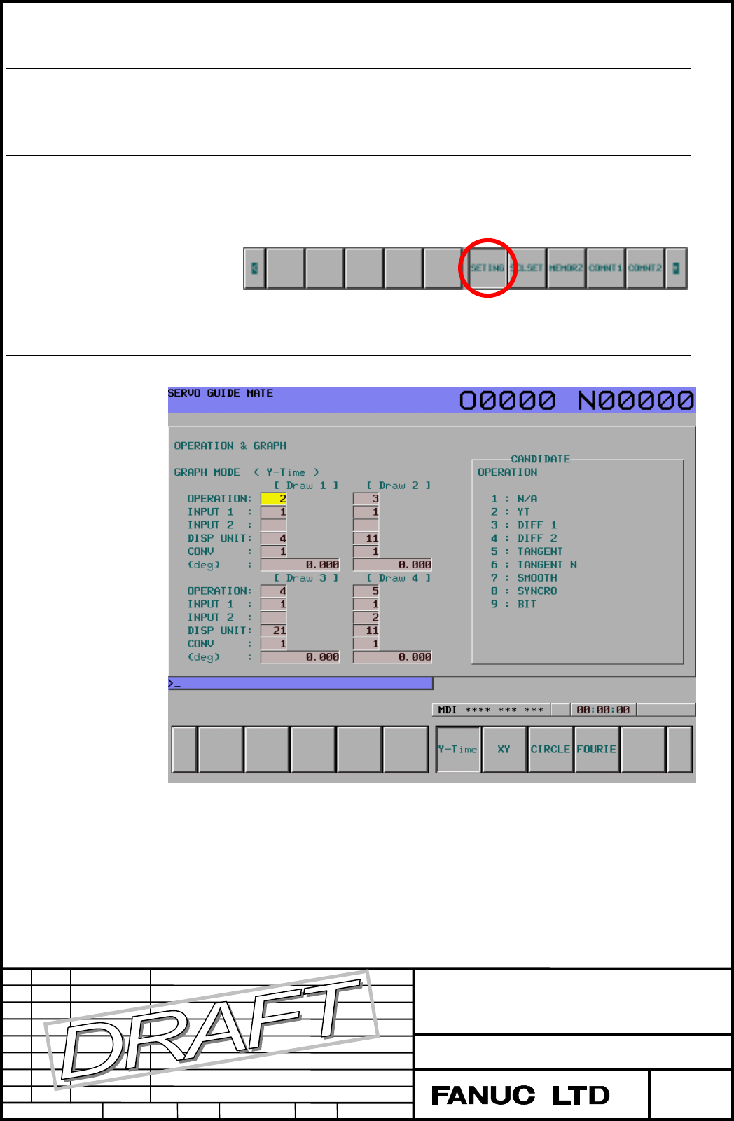
3.1.3 ‘OPERATION & GRAPH' Setup
To display waveform, the operation treatment is set.
3.1.3.1 Soft key operation (a transition from the 'SET CHANNEL' screen) to the setup
screen
To select soft key as follows, 'OPERATION & GRAPH' screen is displayed.
(1) Return a push, a soft key twice [ < ]key (The left of the soft key)
(2) Advance a push, a soft key six times [ + ]key. (The right of the soft key.)
(3) [SETING] is selected.
(4) 'OPERATION & GRAPH' screen is displayed.
3.1.3.2 Constitution of the screen
Screen (softkey type : 12)
Operation method
Cursor movement:
"↑" "↓" "←" "→" … It moves each direction.
Contents Summary of FS16i/18i/21i-TB/MB Servo Guide Mate Specification (Draft) Additional Manual
- Page 1FANUC Series 16i /18i /21i – TB / MB SERVO GUIDE Mate Specification 1 OUTLINE ...................................................................................................................................................................4 1.1 MEASUREMENT AND DRAWING .............................
- Page 23.4.1 ' MEASURE SETTING 'Setup.................................................................................................. 70 3.4.2 'SET CHANNEL ' Setup ........................................................................................................... 73 3.4.3 ' OPERATION & GRAPH 'Set
- Page 38 RESTRICTIONS....................................................................................................................................................112 9 LIBRARY ............................................................................................................................
- Page 41 Outline The SERVO GUIDE Mate is embedded the waveform display function of the servo guide which is servo adjustment tool into CNC. There are four kinds of waveform display function with Time order, Contour error, Moving path, Frequency analysis. This function is an option. Title FANUC Series 16i/1
- Page 51.1 Measurement and Drawing The SERVO GUIDE Mate is composed by the following two elements. • Measurement data The data which the position, the torque acquired from CNC • Drawing data The data that operation treatment was done toward the measurement data After data are measured, operation treatment
- Page 61.2 Measurement data • The acquisition data of servo and spindle, a sampling cycle are as follows. Acquisition data Sampling Cycle Maximun data 4 Servo 62.5 µsec ~ 100msec / 1DSP α Spindle 1data / 1unit 8msec only α i Spindle (old SIC mode) α i Spindle 2data / 1unit 500 µsec ~ 100msec (new SIC mode)
- Page 71.3 Drawing data • The result that operation was done is displayed in the graph toward the acquisition data. • Four maximum waveform is displayed at the same time. Title FANUC Series 16i/18i/21i-TB/MB SERVO GUIDE Mate Specification Drawing No. A-79087EN Page Ed. Date Design Description Date 2003.03.
- Page 82 Operation that takes out SERVO GUIDE Mate screen After a function key [ SYSTEM ] is pushed, the soft key of right end is pushed several times, and SERVO GUIDE Mate screen is displayed by the soft key [S-GUID]. SYSTEM [ S-Guid ] [Y-Time ] (Time display) [ XY ] (Moving path display) [CIRCLE] (Contou
- Page 93 Operating procedure The SERVO GUIDE Mate acquires the data of servo and spindle, operation treatment is done and the waveform is displayed. It describes it about the operation of waveform display function. In SERVO GUIDE Mate, to measure the data and display waveform on the screen, setting and ope
- Page 103.1 Time order (Y-TIME) 3.1.1 'MEASURE SETTING’ Setup Data score, Trigger(Path, N-number), Sampling Cycle are Set. 3.1.1.1 Soft key operation to the setup screen To select the soft key as follows, measure setting screen is displayed. (1) [Y-Time] is selected (2) [SAMPLE] is selected (3) [DATA] is se
- Page 113.1.1.2 Constitution of the screen Screen (softkey type : 12) Operation method Cursor movement : “↑" "↓" "←" "→" … It moves each direction. Title FANUC Series 16i/18i/21i-TB/MB SERVO GUIDE Mate Specification Drawing No. A-79087EN Page Ed. Date Design Description Date 2003.03.07 Desig. Kageyama Apprv
- Page 12Screen ( softkey type : 7 ) Operation method Cursor movement : “↑" "↓" … It moves each direction. Switching of the candidacy: "→" … the following item "←" … the preceding item Title FANUC Series 16i/18i/21i-TB/MB SERVO GUIDE Mate Specification Drawing No. A-79087EN Page Ed. Date Design Description D
- Page 13Explanation The next item can be confirmed and set on the measure setting screen. Attention) When measurement is started, these item are decided how to acquire the data. Therefore, the changes of setting on the screen isn't reflected toward the data that it has already been measured. ( It is reflect
- Page 14TRIGGER PATH The system that acquires data is designated. The list of numerical value to set up is displayed on “the candidate”. The details of trigger path is as follows. Selecting number Contents Remarks 1 PATH1 The 1ST system 2 PATH2 The 2nd systems 3 PATH3 The 3rd systems 5 LOADER Loader * Actua
- Page 15SAMPLING CYCLE (SERVO) SAMPLING CYCLE (SPINDLE) The sampling cycle of the meassurement is set. It sets individually with the servo axis and the spindle axis. In the case that the sampling cycle is different between the servo and spindle, the long setting data of sampling cycle interpolated the strai
- Page 16The list of numerical value to set up is displayed in “the candidate”. The details of the sampling cycle(servo) on the candidate is as follows. Selecting number Contents 1 100 msec 2 50 msec 3 20 msec 4 10 msec 5 5 msec 6 2 msec 7 1 msec 8 500 µsec 9 250 µsec 10 125 µsec 11 62.5 µsec The details of
- Page 17Input condition 1) sampling cycle (servo): The possibility speed that selects by the binding of the HRV control changes HRV1 control designation … 500µsec ~ 100msec HRV2 control designation … 250µsec ~ 100msec HRV3 control designation … 62.5µsec ~ 100msec * The control designation of the fast speed
- Page 18DATE / TIME The time when measured data is displayed. (Read only, cursor movement impossible) Input condition 1) It can't be inputted. AUTO-SCALING An auto-scale changes a scale automatically so that the whole of the waveform may be put within the indication range of the graph. It is chosen whether
- Page 19SYNC. ( SV-SP ) In case of interpolating between servo axis and spindle axis by the Cs contour control, When sampling cycle is different and temporal synchronous is not match, “2:SYNCHRONOUS” is selected. The list of numerical value to set up is displayed in “the candidate”. The details of synchrono
- Page 203.1.2 'SET CHANNEL' Setup The measurement axes, the kind of the data, a unit are set. 3.1.2.1 Soft key operation (a transition from the 'MEASURE SETTING' screen) to the setup screen To select soft key as follows, “SET CHANNEL” screen is displayed. (1) [CH SET] is selected. (2) 'SET CHANNEL' screen i
- Page 21Screen (softkey type : 7) Operation method Cursor movement : "↑" "↓" … It moves each direction Switching of the candidacy: "→" … the following item "←" … the preceding item "Page↓" … Following page is displayed. "Page↑" … Preceding page is displayed. Explanation The next item can be confirmed and ca
- Page 22AXIS The axis for sampling is set. The list of numerical value to set up is displayed in "the candidate". The details of the axis is as follows. Selecting Contents Remarks Selecting Contents Remarks number number 0 Channel invalid 24 Servo axis 4 3 path 1 Servo axis 1 1 path 25 Servo axis 5 3 path 2
- Page 23TYPE The list of numerical value to set up is displayed in “the candidate”. The explanation of the item is displayed to "the explanation". Title FANUC Series 16i/18i/21i-TB/MB SERVO GUIDE Mate Specification Drawing No. A-79087EN Page Ed. Date Design Description Date 2003.03.07 Desig. Kageyama Apprv.
- Page 24The details of the kind (servo) is as follows. Selecting Symbol Contents (the explanation screen display) Remarks number 1 VCMD Velocity command ( VCMD ) Default physical value is 3750(min-1), but if the axis is using Linear Motor, the value depends on the resolution of position encoder 2 TCMD Torqu
- Page 25The details of the kind (spindle) is as follows. Selecting Symbol Contents (the explanation screen display) Remarks 1 number SPEED Motor speed 4096pulse is equal to 1(min-1). 2 INORM Motor current 3 TCMD Torque command 16384pulse is equal to 100% current. 4 VCMD Velocity command 4096pulse is equal t
- Page 26UNIT The unit which can be set up is different by the unit. The list of numerical value to set up is displayed in "the candidate". The detail of unit is as follows. Selecting Contents Selecting Contents number number 1 Sec 21 mm/sec/sec (mm/sec^2) 2 Msec 22 mm/min/min (mm/min^2) 3 µsec 23 m/sec/sec
- Page 27Possibility unit of the kind (servo) is displayed as follows. Type Selecting unit Type Selecting unit Type Selecting unit 1:VCMD 20:1/min 8:ABS 4:mm 23:SFERR 4:mm 14;m/min 6; µm 6: µm 8:inch 8:inch 9:deg 9:deg 2:TCMD 31:A(p) 15:FREQ 32:Hz 24:DLTCM 31:A(p) 33:% 3:SPEED 20:1/min 16:FRTCM 32:Hz 25:OVCL
- Page 28CONV.COEF The weight (a numerator = about physical value) of the data which is selected at the kind of each channel is set. Moving distance per 1 pulse toward poritioning data like POSF, 3750 toward VCMD and SPEED, and maximum electric current of amplifier toward TCMD are set up. Input condition 1)
- Page 293.1.3 ‘OPERATION & GRAPH' Setup To display waveform, the operation treatment is set. 3.1.3.1 Soft key operation (a transition from the 'SET CHANNEL' screen) to the setup screen To select soft key as follows, 'OPERATION & GRAPH' screen is displayed. (1) Return a push, a soft key twice [ < ]key (The l
- Page 30Screen (softkey type : 7) Operation method Cursor movement: "↑" "↓" … It moves each direction. Switching of the candidacy: "→" … the following item "←" … the preceding item "Page↓" … Following page is displayed. "Page↑" … Preceding page is displayed. Explanation The next item can be confirmed and ca
- Page 31Operation The list of numerical value to set up is displayed in "the candidate". The details of the operation is as follows. Selecting number Contents Remarks 1 N/A It isn't used. 2 YT 3 DIFF1 1st order differential data of position will be shown. (It means velocity.) The vertical axis shows the amo
- Page 32* Because the operation of Y-Time links with operation of Fourie, in case of setting N/A, it is set to the operation of Fourie too. And, in case that data is set to except N/A, “31” is set to Fourie. (When the operation of Fourier is changed, the operation of Y-Time isn't renewed.) Input condition 1
- Page 33INPUT 1 By the value of the operation and coordinate conversion, setting value is changed. The list of numerical value to set up is displayed in “the candidate”. The details of input 1 is as follows. Selecting number Contents 1 CH 1 2 CH 2 3 CH 3 4 CH 4 Input condition 1) The number that is displaye
- Page 34INPUT 2 By the value of operation and coordinate conversion, setting value is changed. The list of numerical value to set up is displayed in “the candidate”. The details of input 2 is as follows. Selecting number Contents Selecting number Contents 1 CH 1 16 BIT 6 2 CH 2 17 BIT 7 3 CH 3 18 BIT 8 4 CH
- Page 35DISP UNIT The unit which can be set is changed by the value of operation and Input 1. The list of numerical value to set up is displayed in “the candidate”. Input condition 1) The number that is displayed on the candidate can be selected. (Candidate display is different by the channel setting. ) « R
- Page 36CONV The list of numerical value to set up is displayed in " the candidate ". The details of coordinate conversion is as follows. Selecting number Contents 1 Normal 2 Polar 3 Angular Input condition 1) The selecting number on “the candidate” can be inputted by the following condition. Operation CONV
- Page 37( deg ) Input condition 1) -99999.999 ~ +99999.999 Title FANUC Series 16i/18i/21i-TB/MB SERVO GUIDE Mate Specification Drawing No. A-79087EN Page Ed. Date Design Description Date 2003.03.07 Desig. Kageyama Apprv. 37/131�
- Page 383.1.4 ' SCALE ' Setup The scale of waveform is set up. 3.1.4.1 Soft key operation to the setup screen(A transition from the 'OPERATION & GRAPH' screen) To select soft keys as follows, the 'scale' screen is displayed. (1)[<] key (the soft key left) 1 time a soft key is returned. (2)[SCLSET] is select
- Page 39Screen (softkey type : 7) Operation method Cursor movement: "↑" "↓" … It moves each direction. Explanation The next item can be confirmed and can be set in the scale screen. Title FANUC Series 16i/18i/21i-TB/MB SERVO GUIDE Mate Specification Drawing No. A-79087EN Page Ed. Date Design Description Dat
- Page 40Draw1 ~ Draw4 - ORIGIN The center coordinate of the displaying data (Draw1∼Draw4 and vertical axis) is set. Input condition 1) -99999.999 ~ +99999.999 -9999.9999 ~ +9999.9999 -999.99999 ~ +999.99999 Draw1 ~ Draw4 - DIVISION The value per 1Glide of the displaying data (Draw1∼Draw4 and vertical axis)
- Page 413.1.5 Start of measurement 3.1.5.1 Soft key operation (the transition from ' scale ' the screen) To select soft keys as follows, The measurement is start. (1) Return a push, a soft key once [ < ]key.(The left of the soft key) (2) Advance a push, a soft key once [ + ]key(The right of the soft key) (3
- Page 423.2 Moving path (XY) 3.2.1 'MEASURE SETTING' Setup Data Point, Trigger(Path, N-number) and Sampling Cycle are set up. 3.2.1.1 Soft key operation to the setup screen To select soft keys as follows, measure setting screen is displayed (1) [ XY ] is selected (2) [ SAMPL ] is selected (3) [ DATA ] is se
- Page 433.2.1.2 Composition of a picture Screen (softkey type : 12) Operation method Cursor movement : “↑" "↓" "←" "→" … It moves each direction. Title FANUC Series 16i/18i/21i-TB/MB SERVO GUIDE Mate Specification Drawing No. A-79087EN Page Ed. Date Design Description Date 2003.03.07 Desig. Kageyama Apprv.
- Page 44Screen (softkey type : 7) Operation method Cursor movement : “↑" "↓" … It moves each direction. Switching of the candidacy: "→" … the following item "←" … the preceding item Explanation Each explanation is Refer to "3.1 Time order" screen. Title FANUC Series 16i/18i/21i-TB/MB SERVO GUIDE Mate Specif
- Page 453.2.2 'SET CHANNEL'Setup The measurement axes, the kind of data and unit are set up. 3.2.2.1 Soft key operation to the setup screen (A transition from the 'MEASURE SETTING' screen) To select soft keys as follows, ‘set channel' screen is displayed. (1) [CH SET] is selected. (2) 'SET CHANNEL' the scre
- Page 46Screen (softkey type : 7) Operation method Cursor movement : "↑" "↓" … It moves each direction Switching of the candidacy: "→" … the following item "←" … the preceding item "Page↓" … Following page is displayed. "Page↑" … Preceding page is displayed. Explanation Each explanation is refer to "3.1 Tim
- Page 473.2.3 ’OPERATION & GRAPH' Setup The operation treatment to display waveform is set up. 3.2.3.1 Soft key operation to the setup screen (A transition from the 'SET CHANNEL' screen) To select soft keys as follows, 'OPERATION & GRAPH' screen is displayed. (1) Return a push, a soft key twice [ < ]key(The
- Page 48Screen (softkey type : 7) Operation method Cursor movement: "↑" "↓" … It moves each direction Switching of the candidacy: "→" … the following item "←" … the preceding item "Page↓" … Following page is displayed. "Page↑" … Preceding page is displayed. Explanation The next item can be confirmed and can
- Page 49Operation The list of numerical value to set up in “the candidate" is displayed The details of the computation is as follows. Selecting number Contents Remarks 1 N/A It does not use it 11 XY Input condition 1) The selecting number on the candidate can be inputted by the following condition. N/A … in
- Page 50Input 2 By the value of operation or coordinate conversion, setting value is changed. The list of numerical value to set up is displayed in “the candidate”. The details of input 2 is as follows. Selecting number Contents 1 CH 1 2 CH 2 3 CH 3 4 CH 4 Input condition 1) The number that is displayed on
- Page 51CONV The list of numerical value to set up is displayed in “the candidate”. The details of coordinate conversion is as follows. Selecting number Contents 1 Normal 2 Polar 3 Angular Input condition 1) The number displayed in the candidate can be selected by the following condiditon. CONV Condition No
- Page 523.2.4 ' SCALE 'Setup The scale of waveform is set up. 3.2.4.1 Soft key operation to the setup screen (A transition from the 'OPERATION & GRAPH' screen) To select soft keys as follows, 'scale' screen is displayed. (1) [<] key (the soft key left) 1 time a soft key is returned. (2) [SCLSET] is selected
- Page 53Screen (softkey type : 7) Operation method Cursor movement: "↑" "↓" … It moves each direction. Explanation The next item can be confirmed and can be set in the scale screen. Title FANUC Series 16i/18i/21i-TB/MB SERVO GUIDE Mate Specification Drawing No. A-79087EN Page Ed. Date Design Description Dat
- Page 54HORIZ - ORIGIN The center coordinate of the displaying data is set. Input condition 1) -99999.999 ~ +99999.999 -9999.9999 ~ +9999.9999 -999.99999 ~ +999.99999 HORIZ - DIVISION The 1 glide of the displayeng data is set. Input condition 1) 0.001 ~ +99999.999 0.0001 ~ +9999.9999 0.00001 ~ +999.99999 VE
- Page 553.2.5 Start of measurement 3.2.5.1 Soft key operation (the transition from ' SCALE ' the screen) To select soft keys as follows, the measurement is started. (1) Return a push, a soft key once [ < ]key (The left of the soft key) (2) Advance a push, a soft key once [ +]key (The right of the soft key)
- Page 563.3 Contour error (CIRCLE) 3.3.1 ' MEASURE SETTING 'Setup Data score, Trigger(Path, N-number) and Sampling cycle are set up. 3.3.1.1 The soft key operation to the setup screen To select soft keys as follows,'measure setting' screen is displayed (1) [CIRCLE] is selected. (2) [SAMPL] is selected. (3)
- Page 573.3.1.2 Constitution of the screen Screen (softkey type : 12) Operation method Cursor movement : “↑" "↓" "←" "→" … It moves each direction. Title FANUC Series 16i/18i/21i-TB/MB SERVO GUIDE Mate Specification Drawing No. A-79087EN Page Ed. Date Design Description Date 2003.03.07 Desig. Kageyama Apprv
- Page 58Screen (softkey type : 7) Operation method Cursor movement : “↑" "↓" … It moves each direction. Switching of the candidacy: "→" … the following item "←" … the preceding item Explanation Each explanation is refer to "3.1 Time order" screen. Title FANUC Series 16i/18i/21i-TB/MB SERVO GUIDE Mate Specif
- Page 593.3.2 ' SET CHANNEL 'Setup The measurement axes, the kind of data and unit are set up. 3.3.2.1 Soft key operation to the setup screen (A transition from the 'MEASURE SETTING' screen) To select soft keys as follows, 'SET CHANNEL' screen is displayed. (1) [CH SET] is selected. (2) 'SET CHANNEL' the sc
- Page 60Screen (softkey type : 7) Operation method Cursor movement : “↑" "↓" … It moves each direction. Switching of the candidacy: "→" … the following item "←" … the preceding item "Page↓" … Following page is displayed. "Page↑" … Preceding page is displayed. Explanation Each explanation is refer to "3.1 Ti
- Page 613.3.3 ' OPERATION & GRAPH 'Setup The operation treatment to display waveform is set up. 3.3.3.1 Soft key operation to the setup screen (A transition from the 'SET CHANNEL' screen) To select soft keys as follows, 'OPERATION & GRAPH' screen is displayed. (1) Return a push, a soft key twice [ < ] key (
- Page 62Screen (softkey type : 7) Operation method Cursor movement: "↑" "↓" … It moves each direction. Switching of the candidacy: "→" … the following item "←" … the preceding item "Page↓" … Following page is displayed. "Page↑" … Preceding page is displayed. Explanation The next item can be confirmed and ca
- Page 63Operation The list of numerical value to set up is displayed in “the candidate”. The details of the computation is as follows. Selecting number Contents Remarks 1 N/A Does not use 21 CIRCLE Input condition 1) The number displayed in the candidate can be selected by the following condiditon. N/A …inp
- Page 64Input 2 By the value of operation or coordinate conversion, setting value is changed. The list of numerical value to set up is displayed in “the candidate”. The details of input 2 is as follows. Selecting number Contents 1 CH 1 2 CH 2 3 CH 3 4 CH 4 Input condition 1) The number that is displayed on
- Page 65CONV The list of numerical value to set up is displayed in “the candidate”. The details of coordinate conversion is as follows. Selecting number Contents 1 Normal 2 Polar 3 Angular Input condition 1) The number displayed in the candidate can be selected by the following condition. Coordinate convers
- Page 663.3.4 ' SCALE 'Setup The scale of waveform is set up. 3.3.4.1 Soft key operation to the setup screen (A transition from the 'OPERATION & GRAPH' screen) To select soft keys as follows, the 'scale' screen is displayed. (1) Return a push, a soft key once [ < ]key (The left of the soft key) (2) [SCLSET]
- Page 67Screen (softkey type : 7) Operation method Cursor movement: "↑" "↓" "←" "→" … It moves each direction. Explanation The next item can be confirmed and can be set in the scale screen. Title FANUC Series 16i/18i/21i-TB/MB SERVO GUIDE Mate Specification Drawing No. A-79087EN Page Ed. Date Design Descrip
- Page 68H- CENTER The center coordinate (the coordinate of horizontal axis) of the circular arc is set up. Input condition 1) -99999.999 ~ +99999.999 -9999.9999 ~ +9999.9999 -999.99999 ~ +999.99999 V- CENTER The center coordinate (the coordinate of vertical axis) of the circular arc is set up. Input conditi
- Page 693.3.5 Start of measurement 3.3.5.1 Soft key operation (the transition from 'SCALE' the screen) To select soft keys as follows, measurement is started. (1) Return a push, a soft key once [ < ]key (The left of the soft key) (2) Advance a push, a soft key once [ +] key (The right of the soft key) (3) [
- Page 703.4 Frequency analysis (FOURIER) 3.4.1 ' MEASURE SETTING 'Setup Data score, Trigger(Path, N-number) and Sampling cycle are Set up. 3.4.1.1 Soft key operation to the setup screen To select soft keys as follows, the measure setting screen displayed (1) [FOURIE] is selected (2) [SAMPL] is selected (3)
- Page 713.4.1.2 Constitution of the screen Screen (softkey type : 12) Operation method Cursor movement : “↑" "↓" "←" "→" … It moves each direction. Title FANUC Series 16i/18i/21i-TB/MB SERVO GUIDE Mate Specification Drawing No. A-79087EN Page Ed. Date Design Description Date 2003.03.07 Desig. Kageyama Apprv
- Page 72Screen (softkey type : 7) Operation method Cursor movement : “↑" "↓" … It moves each direction. Switching of the candidacy: "→" … the following item "←" … the preceding item Explanation Each explanation is refer to "3.1 Time order" screen. Title FANUC Series 16i/18i/21i-TB/MB SERVO GUIDE Mate Specif
- Page 733.4.2 'SET CHANNEL ' Setup The measurement axis, kind of the data and a unit are set up. 3.4.2.1 Soft key operation to the setup screen (A transition from the 'SET CHANNEL' screen) To select soft keys as follows, the 'set channel’ screen is displayed. (1) [CH SET] is selected. (2) 'SET CHANNEL' scre
- Page 74Screen (softkey type : 7) Operation method Cursor movement : "↑" "↓" … It moves each direction Switching of the candidacy: "→" … the following item "←" … the preceding item "Page↓" … Following page is displayed. "Page↑" … Preceding page is displayed. Explanation Each explanation is refer to "3.1 Tim
- Page 753.4.3 ' OPERATION & GRAPH 'Setup The operation treatment to display waveform is set up. 3.4.3.1 Soft key operation to the setup screen (A transition from the 'SET CHANNEL' screen) To selecte soft keys as follows, the 'OPERATION & GRAPH' screen is displayed. (1) Return a push, a soft key twice [ < ]k
- Page 76Screen (softkey type : 7) Operation method "Page↓" … Following page is displayed. "Page↑" … Preceding page is displayed. Explanation The next item can be confirmed and can be set in the operation & gaph screen. Title FANUC Series 16i/18i/21i-TB/MB SERVO GUIDE Mate Specification Drawing No. A-79087EN
- Page 77Operation The list of numerical value to set up is displayed in “the candidate”. The details of the computation is as follows. Selecting number Contents Remarks 1 N/A Does not use 31 FOURIER Input condition 1) The number displayed in the candidate can be selected by the following condiditon. N/A … i
- Page 783.4.4 ' SCALE 'Setup The scale of waveform is set up. 3.4.4.1 Soft key operation to the setup screen (A transition from the 'OPERATION & GRAPH' screen) To select soft keys as follows, the 'scale' screen is displayed. (1) Return a push, a soft key once [ < ]key (The left of the soft key) (2) [SCLSET]
- Page 79Screen (softkey type : 7) Operation method Cursor movement: "↑" "↓" "←" "→" … It moves each direction. Explanation Title FANUC Series 16i/18i/21i-TB/MB SERVO GUIDE Mate Specification Drawing No. A-79087EN Page Ed. Date Design Description Date 2003.03.07 Desig. Kageyama Apprv. 79/131
- Page 80GAIN - ORIGIN The value of the central strength data of the graph is set. Input condition 1) -99999.999 ~ +99999.999 -9999.9999 ~ +9999.9999 -999.99999 ~ +999.99999 GAIN - DIVISION The value of 1 glide is set. Input condition 1) 0.001 ~ +99999.999 0.0001 ~ +9999.9999 0.00001 ~ +999.99999 PHASE - ORI
- Page 81FREQ - MIN The minimum value of the horizontal axis is set. Input condition 1) 0.001 ~ +99999.999 FREQ - MAX The maximum value of the horizontal axis is set. Input condition 1) 0.001 ~ +99999.999 Title FANUC Series 16i/18i/21i-TB/MB SERVO GUIDE Mate Specification Drawing No. A-79087EN Page Ed. Date
- Page 823.4.5 Start of measurement 3.4.5.1 Soft key operation (the transition from ‘SCALE' the screen) To select soft keys as follows, the measurement is started. (1) Return a push, a soft key once [ < ]key. (The left of the soft key) (2) Advance a push, a soft key once [ + ]key(The right of the soft key) (
- Page 833.5 Display of 'LIST' The list of setting data is displayed and confirmed. 3.5.1 Soft key operation to the 'list' screen. (‘SCALE’Transition from the screen) To select soft keys as follows, the 'list' screen is displayed. (1) Return a push, a soft key once [ < ]key. (The left of the soft key) (2) Ad
- Page 843.5.2 Constitution of the screen Screen (softkey type : 12) Title FANUC Series 16i/18i/21i-TB/MB SERVO GUIDE Mate Specification Drawing No. A-79087EN Page Ed. Date Design Description Date 2003.03.07 Desig. Kageyama Apprv. 84/131�
- Page 85Screen (softkey type : 7) Explanation The setting data of the measure setting screen and set channel screen is displayed. Title FANUC Series 16i/18i/21i-TB/MB SERVO GUIDE Mate Specification Drawing No. A-79087EN Page Ed. Date Design Description Date 2003.03.07 Desig. Kageyama Apprv. 85/131�
- Page 864 Example Operationg instructions of SERVO GUIDE Mate is explained with concrete exsamples. Title FANUC Series 16i/18i/21i-TB/MB SERVO GUIDE Mate Specification Drawing No. A-79087EN Page Ed. Date Design Description Date 2003.03.07 Desig. Kageyama Apprv. 86/131�
- Page 874.1 Tuning of square 4.1.1 Preparation of the program « Reference program » G91G94 N1 G01X20.000F2000.000 G01Y-20.000F2000.000 G01X-20.000F2000.000 G01Y20.000F2000.000 G04X1. N999 G04X1. M02 4.1.2 Preparation of data measurement 1) Soft key [XY] pushed. 2) Soft key [SAMPL] pushed. 3) Soft key [DATA]
- Page 887) Push [LIST] key and the setting values are confirmed. 8) Push [GRAPH] key. 9) A continuation menu key[>] is pushed, and [SETING] is pushed. « Reference setting » The data that is measured with CH1 and CH2 is set up to display with Draw1 on the XY screen. Operation Input 1 Input 2 Disp Unit CONV.
- Page 894.2 Tuning Circle 4.2.1 Preparation of the program « Reference program » G91 G94 N1 G17 G02 I-10.000 F2000.000 G17 G02 I-10.000 F2000.000 G04 X1. N999 G04 X1. M02 4.2.2 Preparation of data measurement 1) Soft key [XY] pushed. 2) Soft key [SAMPL] pushed. 3) Soft key [DATA] pushed. 4) The soft key [CH
- Page 907) Soft key [LIST] pushed, and, setting values are confirmed. 8) Soft key [GRAPH] pushed. 9) A continuation menu key[>] is pushed, and [SETING] is pushed. 10) The XY screen is displayed. « Reference setting » The data that is measured with CH1 and CH2 is set up to display with Draw1 on the XY screen
- Page 914.2.4 Form error display 1) A returned key [<] is pushed, and soft key [CIRCLE] is pushed.. 2) A continuation menu key[>] is pushed, and soft key [SETING] is pushed. 3) The CIRCLE screen is displayed. « Reference setting » The data that is measured with CH1 and CH2 is set up to display with Draw1 on
- Page 925 Function detailed It explains about the details of " Time order, Moving path, Contour error, Frequency analysis". And, it explains about input and output of the waveform and the comparison. Title FANUC Series 16i/18i/21i-TB/MB SERVO GUIDE Mate Specification Drawing No. A-79087EN Page Ed. Date Desi
- Page 935.1 Time order The horizontal axis is displayed as a time, vertical axes are displayed as the unit of each data. The number of Draw that can be displayed is four, and each Draw has a scale of vertical axis. A scale of vertical axis and displaying graph are same color. Operation of the graph The oper
- Page 94[D1DISP] : The display or nondisplay is changed about the Draw1 waveform. [D1 ↑] : A Draw1 waveform is moved to the vertical axis side upward direction. [D1 ↓] : A Draw1 waveform is moved to the vertical axis side downward direction. [D1VZMI] : A Draw1 waveform is expanded into the vertical axis sid
- Page 955.2 Moving path The scale of vertical axis can be setting freely. It draws one line by using two data (for example, in case of the circlular arc of XY plane, the position data of X axis and Y axis is used). Title FANUC Series 16i/18i/21i-TB/MB SERVO GUIDE Mate Specification Drawing No. A-79087EN Pag
- Page 96Operation of the graph The operation is done by the softkey. [↑] : A waveform is moved to the vertical axis side upward direction. [↓] : A waveform is moved to the vertical axis side downward direction. [←] : A waveform is moved in the horizontal axis side left direction. [→] : A waveform is moved i
- Page 975.3 Contour error The radius and center of the perfect circle is operated previously and the error from the perfect circle is expanded and displayed. Title FANUC Series 16i/18i/21i-TB/MB SERVO GUIDE Mate Specification Drawing No. A-79087EN Page Ed. Date Design Description Date 2003.03.07 Desig. Kage
- Page 98Operation of the graph The operation is done by the softkey. [↑] : A waveform is moved to the vertical axis side upward direction. [↓] : A waveform is moved to the vertical axis side downward direction. [←] : A waveform is moved in the vertical axis side left direction. [→] : A waveform is moved in
- Page 995.4 Frequency analysis YT Mode FOURIER Mode The waveform that is displayed with YT mode is converted by the digital Fourier and displayed. Title FANUC Series 16i/18i/21i-TB/MB SERVO GUIDE Mate Specification Drawing No. A-79087EN Page Ed. Date Design Description Date 2003.03.07 Desig. Kageyama Apprv.
- Page 100Operation of the graph The operation is done by the softkey. [MAGN↑] : The vertical axis of the strength display of all the waveform (upper display on the screen) is moved upward. [MAGN↓] : The vertical axis of the strength display of all the waveform (upper display on the screen) is moved downward.
- Page 1015.5 Memory Reading and saving of the measurement data, and reading and saving of the data acquisition condition and data dispay condition are done. When soft key [MEMORZ] is pushed, it changes to the following soft key. Title FANUC Series 16i/18i/21i-TB/MB SERVO GUIDE Mate Specification Drawing No.
- Page 1025.5.1 Read S-RAM card or ATA card can be used. When soft key [READ] is pushed, a file list in the memory card is displayed on the screen. A file name, a date and size (KB unit) are dispalyed with 1 column (soft key 7 type) or 2 column (soft key 12 type). The mode is changed to the [EDIT] mode. The n
- Page 1035.5.2 Punch S-RAM card or ATA card can be used. When soft key [PUNCH] is pushed, a file list in the memory card is displayed on the screen. A file name, a date and size (KB unit) are dispalyed with 1 column (soft key 7 type) or 2 column (soft key 12 type). The mode is changed to the [EDIT] mode. The
- Page 1045.6 Comparison To read the data that is measured before, it can be compared with the measurement data this time. This function is effective in the Moving path and Contour error only. When soft key [DIFF] is pushed, it changes to the following soft key. 5.6.1 Read S-RAM card or ATA card can be used.
- Page 1055.6.2 Erase The data read for the comparison are erased. (A graph for the comparison stops being displayed.) Title FANUC Series 16i/18i/21i-TB/MB SERVO GUIDE Mate Specification Drawing No. A-79087EN Page Ed. Date Design Description Date 2003.03.07 Desig. Kageyama Apprv. 105/131�
- Page 1066 Data It is described about data to set with the SERVO GUIDE Mate. Title FANUC Series 16i/18i/21i-TB/MB SERVO GUIDE Mate Specification Drawing No. A-79087EN Page Ed. Date Design Description Date 2003.03.07 Desig. Kageyama Apprv. 106/131�
- Page 1076.1 Data that is set with the candidacy from the setting screen Screen Item Data type Decimal point Correspondence range MEASURE SETTING TRIGGER PATH BYTE No decimal point SAMPLING CYCLE BYTE No decimal point (SERVO) SAMPLING CYCLE BYTE No decimal point (SPINDLE) AUTO-SCALING BYTE No decimal point S
- Page 1086.2 Data that is set with input from the setting screen Screen Data type Decimal point Correspondence range MEASURE SETTING DATA POINTS DWORD No decimal point 2∼10000 TRIGGER SEQ.NO DWORD No decimal point 0∼99999 SET CHANNEL CONV. COEF DWORD The 3rd decimal point -99999.999∼99999.999 (fixation) (But
- Page 109Screen Data type Decimal point Correspondence range SCALE (CIRCLE) H-CENTER DWORD Dependent on 2000#0 By 8 digits of maximum 9, (PLC) decimal point position variability V-CENTER DWORD Dependent on 2000#0 By 8 digits of maximum 9, (PLC) decimal point position variability RADIUS DWORD Dependent on 200
- Page 110The position of the decimal point which is dependent on 2000#0 (PLC) and corresponding range 2000#0(PLC) Operation & Graph Decimal Correspondence range setting display unit point Scale or radius Except for scale or radius 0 Except for inch The 3rd 0∼99999.999 -99999.999∼99999.999 decimal point Inch
- Page 1117 Warning Messages Warning messages that is displayed with this function are as follows. Message Description THERE IS INVALID CHARACTER The one except for the numerical value was inputted. (Input of a comment is removed.) INPUT . OR – MORE THAN TWICE "." "-" was inputted more than twice. TOO MANY DI
- Page 1128 Restrictions 1) The SERVO GUIDE Mate is made by C language executor. 2) In case of the SERVO GUIDE Mate screens, when RESET key is pushed, it is only cleared warning messages and buffer of key-in. And, the data can not be inputted during RESET and EMERGENCY. 3) The SERVO GUIDE Mate is actuated in
- Page 1139 Library The built-in procedure of SERVO GUIDE Mate is described. Title FANUC Series 16i/18i/21i-TB/MB SERVO GUIDE Mate Specification Drawing No. A-79087EN Page Ed. Date Design Description Date 2003.03.07 Desig. Kageyama Apprv. 113/131�
- Page 1149.1 The connection procedure of SAT_LIB. LNK 9.1.1 Installation of the file Copy the file of the following which is in a CD-ROM to provide from FANUC on the directory for the application preparation. Task 1 SAT_LIB.LNK The function library of SERVO GUIDE Mate SAT_LIB.H The header file for the functi
- Page 115Task 3 SAT_ONES.LNK The function library of the ServoData acquisition function. SAT_LIB3.H The header file for the function library of the ServoData acquisition function Specification look of the function that is included to SAT_ONES. LNK The acquisition function of ServoData(cnc_SatOneShot) Functio
- Page 1169.1.2 Initialization of the user screen C language Set up a screen number CRT_OFS_TLLF (#include crt.h) as a user screen in the initialization of the executor application. # include
int crt_table[] = CRT_OFS_TLLF, The screen number which MTB uses as a user screen }; : cnc_SatInitialize(); /* - Page 1179.1.4 Actual one's whereabouts law Task1 SAT_LIB.H and SAT_DRAM.H are include in the source file which the library function of SERVO GUIDE Mate is used for. Attention) When a color display vessel with the VGA display is used, after it deals with initialization, surely display other NC screens once.
- Page 1189.1.5 A built-in method to CNC After combined with C language application, the file “CEX ****” is loaded to the Flash memory of CNC by BOOT SYSTEM. 9.1.6 Semaphore ID Semaphore ID = 1 is used with SERVO GUIDE Mate. Because common data are used between 'the task 1' and 'the task 3'. 9.1.7 Cautions Th
- Page 11910 Parameters It is described about parameters to use with this function. Data Number #7 #6 #5 #4 #3 #2 #1 #0 SVG CLR 14500 Data type : Bit CLR Display of SERVO GUIDE Mate is 0 : Color. 1 : Monochrome. SVG SERVO GUIDE Mate Function is 0 : not used. 1 : used. Data Number #7 #6 #5 #4 #3 #2 #1 #0 SSP S
- Page 120Number Data Measurement data score 14505 Data type : Double Word Data range : 0~10,000 Number Data Measurement trigger system 14506 Data type : Byte Data range : 0~5 When 0 is set up, it is made path 1. The loader is setup value 5. Setup value 4 is reserve. Number Data Sequence number of the measure
- Page 121Number Data Measurement axis (channel 1) 14511 Measurement axis (channel 2) 14512 Measurement axis (channel 3) 14513 Measurement axis (channel 4) 14514 Data type : Byte Data range : 1~8 : servo (1 path) 11~18 : servo (2 path) 21~28 : servo (3 path) 101~104 : servo (loader) 1~-4 : spindle (1 path) 11
- Page 122Number Data Measurement data conversion coefficient (channel 1) 14523 Measurement data conversion coefficient (channel 2) 14524 Measurement data conversion coefficient (channel 3) 14525 Measurement data conversion coefficient (channel 4) 14526 Data type : Double word Number Data Measurement data con
- Page 123Number Data Measurement data shift (channel 1) 14539 Measurement data shift (channel 2) 14540 Measurement data shift (channel 3) 14541 Measurement data shift (channel 4) 14542 Data type : Double word Number Data Data shift 1 (channel 1) 14543 Data shift 2 (channel 1) 14544 Data shift 1 (channel 2) 1
- Page 124Number Data Y-T graph computation (Draw1) 14556 Y-T graph computation (Draw2) 14557 Y-T graph computation (Draw3) 14558 Y-T graph computation (Draw4) 14559 Data type : Byte Number Data Y-T graph input 1 (Draw1) 14560 Y-T graph input 1 (Draw2) 14561 Y-T graph input 1 (Draw3) 14562 Y-T graph input 1 (
- Page 125Number Data Y-T graph coordinate change choice (Draw1) 14572 Y-T graph coordinate change choice (Draw2) 14573 Y-T graph coordinate change choice (Draw3) 14574 Y-T graph coordinate change choice (Draw4) 14575 Data type : Byte Number Data Y-T graph angle of inclination (Draw1) 14576 Y-T graph angle of
- Page 126Number Data X-Y graph display unit (Draw1) 14586 X-Y graph display unit (Draw2) 14587 Data type : Byte Number Data X-Y graph coordinate change choice (Draw1) 14588 X-Y graph coordinate change choice (Draw2) 14589 Data type : Byte Number Data X-Y graph angle of inclination (Draw1) 14590 X-Y graph ang
- Page 127Number Data Circle graph coordinate change choice 14596 Data type : Byte Number Data Circle graph angle of inclination 14597 Data type : Double word umber Data Fourier graph computation (Draw1) 14598 Fourier graph computation (Draw2) 14599 Fourier graph computation (Draw3) 14600 Fourier graph comput
- Page 128Number Data Acceleration filter location 14606 Data type : Double word Number Data Y-T graph center location (Draw1) 14607 Y-T graph center location (Draw2) 14608 Y-T graph center location (Draw3) 14609 Y-T graph center location (Draw4) 14610 Data type : Double word Number Data Y-T graph vertical ax
- Page 129Number Data X-Y graph horizontal axis indication 14618 Data type : Double word Number Data X-Y graph vertical axis center coordinate 14619 Data type : Double word Number Data X-Y graph vertical axis indication 14620 Data type : Double word Number Data Circle graph horizontal axis center coordinate 1
- Page 130Number Data Fourier graph strength indication 14627 Data type : Double word Number Data Fourier graph phase center location 14628 Data type : Double word Number Data Fourier graph phase indication 14629 Data type : Double word Number Data Fourier graph frequency minimum value 14630 Data type : Doubl
- Page 131Number Data Board graph frequency minimum value 14636 Data type : Double word Number Data Board graph frequency maximum value 14637 Data type : Double word Number Data Current graph mode 14638 Data type : Byte Title FANUC Series 16i/18i/21i-TB/MB SERVO GUIDE Mate Specification Drawing No. A-79087EN