Series 0i - Model A Connection manual (Function) Page 442
Connection manual (Function)
B–63503EN–1/01
9. SPINDLE SPEED FUNCTION
426
Feed axis and direction select signal +Jn, *Jn <G100, G102> (Input)
Manual handle feed axis select signal HSnA, HSnB, HSnC, HSnD
<G018, G019> (Input) (Refer to respective items in this manual)
The Cs contour control axis can be manually operated in the same way as
normal servo axes, except for a manual reference position return. In the
spindle speed control mode, however, manual operations for the Cs
contour control axis must be inhibited using the PMC ladder, etc.
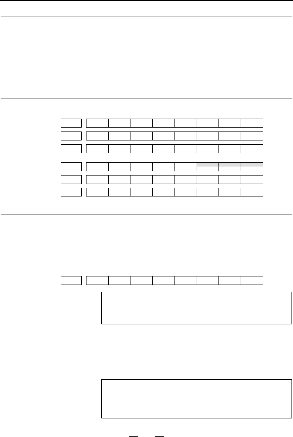
#7 #6 #5 #4 #3 #2 #1 #0
CONG027
G028 GR2 GR1
MRDYAG070 SFRA SRVA CTH1A CTH2A
#7 #6 #5 #4 #3 #2 #1 #0
F034 GR3O GR2O GR1O
F044 FSCSL
F094 ZP4 ZP3 ZP2 ZP1
The following describes major parameters.
In addition, parameters such as axis feedrate, acceleration/deceleration,
and display can be used. Also, digital servo parameters (No. 2000 ∼) for
the Cs contour axis are not required to be set.
#7
8133
#6 #5 #4 #3 #2
SCS
#1 #0
NOTE
When this parameter has been set, the power must be
turned off before operation is continued.
[Data type] Bit
SCS Specifies whether to use Cs contour control, as follows :
0 : Not to use.
1 : Use.
NOTE
It is impossible to select spindle positioning–based Cs
contour control and serial spindle–based Cs contour control
at the same time.
Signals on manual
operation
Signal address
Parameter
Contents Summary of Series 0i - Model A Connection manual (Function)
- Page 1CONNECTION MANUAL (FUNCTION) B-63503EN-1/01�
- Page 2Ȧ No part of this manual may be reproduced in any form. Ȧ All specifications and designs are subject to change without notice. In this manual we have tried as much as possible to describe all the various matters. However, we cannot describe all the matters which must not be done, or which cannot be
- Page 3B–63503EN–1/01 DEFINITION OF WARNING, CAUTION, AND NOTE DEFINITION OF WARNING, CAUTION, AND NOTE This manual includes safety precautions for protecting the user and preventing damage to the machine. Precautions are classified into Warning and Caution according to their bearing on safety. Also, suppl
- Page 4
- Page 5B–63503EN–1/01 PREFACE PREFACE This manual describes all the NC functions required to enable machine tool builders to design their CNC machine tools. The following items are explained for each function. 1. General Describes feature of the function. Refer to Operator’s manual as requied. 2. Signals D
- Page 6PREFACE B–63503EN–1/01 Signal description Relation of interface signals among the CNC, the PMC and the machine tool is shown below: CNC PMC MT G000 or later X1000 or later Built in I/O (Basic) Y1000 or F000 or later later Machine tool X 000 or later FANUC I/O Link Y 000 or (Optional) later NOTE For
- Page 7B–63503EN–1/01 PREFACE Parameter description Parameters are classified by data type as follows : Dta type Valid data range Remarks Bit 0 or 1 Bit axis Byte 0 to"127 In some parameters, signs are ig- Byte axis 0 to 255 nored. Word 0 to"32767 Word axis 0 to 65535 2–word " 0 to"99999999 2–word axis NOT
- Page 8PREFACE B–63503EN–1/01 D Notation of bit type and bit axis type parameters Data No. Data (#0 to #7 indicates bit position) #7 #6 #5 #4 #3 #2 #1 #0 0000 SEQ INI ISO TVC D Notation of parameters other than bit type and bit axis type Data No. Data 1023 Servo axis number of a specific axis NOTE In an it
- Page 9B–63503EN–1/01 PREFACE Related Manuals The table below lists manuals related to MODEL A of Series 0i. In the table, this manual is marked with an asterisk(*). Table 1 Related manuals Specification Manual name Number DESCRIPTIONS B–63502EN CONNECTION MANUAL (HARDWARE) B–63503EN CONNECTION MANUAL (FUN
- Page 10
- Page 11B–63503EN–1/01 Table of Contents DEFINITION OF WARNING, CAUTION, AND NOTE . . . . . . . . . . . . . . . . . . . . . . . . . . . . . s–1 PREFACE . . . . . . . . . . . . . . . . . . . . . . . . . . . . . . . . . . . . . . . . . . . . . . . . . . . . . . . . . . . . . . . . . . . p–1 1. AXIS CONTROL .
- Page 12B–63503EN–1/01 TABLE OF CONTENTS 4. REFERENCE POSITION ESTABLISHMENT . . . . . . . . . . . . . . . . . . . . . . . . . . . . . . . . . . 127 4.1 MANUAL REFERENCE POSITION RETURN . . . . . . . . . . . . . . . . . . . . . . . . . . . . . . . . . . . . . . . 128 4.2 SETTING THE REFERENCE POSITION WITHO
- Page 13TABLE OF CONTENTS B–63503EN–1/01 7.1.6.1 Rapid traverse override . . . . . . . . . . . . . . . . . . . . . . . . . . . . . . . . . . . . . . . . . . . . . . . . . . . 256 7.1.6.2 Feedrate override . . . . . . . . . . . . . . . . . . . . . . . . . . . . . . . . . . . . . . . . . . . . . . . . . . . .
- Page 14B–63503EN–1/01 TABLE OF CONTENTS 9.10.6.4 Signals related to second spindle rigid tapping . . . . . . . . . . . . . . . . . . . . . . . . . . . . . . . . . 465 9.10.6.5 Signal addresses . . . . . . . . . . . . . . . . . . . . . . . . . . . . . . . . . . . . . . . . . . . . . . . . . . . . . . . . .
- Page 15TABLE OF CONTENTS B–63503EN–1/01 12.1.3 Help Function . . . . . . . . . . . . . . . . . . . . . . . . . . . . . . . . . . . . . . . . . . . . . . . . . . . . . . . . . . . . . . 616 12.1.4 Displaying Alarm History . . . . . . . . . . . . . . . . . . . . . . . . . . . . . . . . . . . . . . . . . . .
- Page 16B–63503EN–1/01 TABLE OF CONTENTS 15.5 EXTERNAL KEY INPUT . . . . . . . . . . . . . . . . . . . . . . . . . . . . . . . . . . . . . . . . . . . . . . . . . . . . . . . . . 780 15.6 DIRECT OPERATION BY Personal computer connected to the HSSB . . . . . . . . . . . . . . . . . . . . . 785 APPENDIX A. IN
- Page 17B–63503EN–1/01 1. AXIS CONTROL 1 AXIS CONTROL 1
- Page 181. AXIS CONTROL B–63503EN–1/01 1.1 CONTROLLED AXES General Item M series T series No. of basic 1–path 3 axes 2 axes controlled axes Controlled axes 1–path Max. 4 axes Max. 4 axes expansion (Including the Cs axis) (Including the Cs axis) (total) Basic 1–path Max. 4 axes Max. axes simultaneously contr
- Page 19B–63503EN–1/01 1. AXIS CONTROL 1.2 SETTING EACH AXIS 1.2.1 Name of Axes General Each axis that is controlled by the CNC (including those controlled by the PMC) must be named. Select and set names from among X, Y, Z, A, B, C, U, V, and W (with parameter 1020). The names of the basic axes, however, ar
- Page 201. AXIS CONTROL B–63503EN–1/01 Reference item OPERATOR’S MANUAL NAMES OF AXES (For Machining Center) (B–63514EN) OPERATOR’S MANUAL NAMES OF AXES (For Lathe) (B–63504EN) 4
- Page 21B–63503EN–1/01 1. AXIS CONTROL 1.2.2 Increment System General The increment system consists of the least input increment (for input ) and least command increment (for output). The least input increment is the least increment for programming the travel distance. The least command increment is the lea
- Page 221. AXIS CONTROL B–63503EN–1/01 NOTE Diameter programming is used only for T series. Whether diameter programming or radius programming is used is selected by parameter DIAx (No. 1006#3) on each axis. Also, parameter IPR (No. 1004#7) can make the least input increment of IS–B and IS–C ten times the l
- Page 23B–63503EN–1/01 1. AXIS CONTROL IPR Whether the least input increment for each axis is set to a value 10 times as large as the least command increment is specified, in increment systems of IS–B and IS–C, mm input. 0 : The least input increment is not set to a value 10 times as large as the least comm
- Page 241. AXIS CONTROL B–63503EN–1/01 1.2.3 Specifying the Rotation Axis General Bit 0 (ROTx) of parameter 1006 can be used to set each axis to a linear axis or rotation axis. Bit 1 (ROSx) of parameter 1006 can be used to select the rotation axis type, A or B, for each axis. See the explanation of the para
- Page 25B–63503EN–1/01 1. AXIS CONTROL Parameter #7 #6 #5 #4 #3 #2 #1 #0 1006 ROSx ROTx NOTE After setting this parameter, turn the power off then on again so that the setting will take effect. [Data type] Bit axis ROTx, ROSx Setting linear or rotation axis. ROSx ROTx Meaning 0 0 Linear axis (1) Inch/metric
- Page 261. AXIS CONTROL B–63503EN–1/01 NOTE ROAx specifies the function only for a rotation axis (for which ROTx, #0 of parameter No. 1006, is set to 1) RABx In the absolute commands, the axis rotates in the direction 0 : In which the distance to the target is shorter. 1 : Specified by the sign of command v
- Page 27B–63503EN–1/01 1. AXIS CONTROL Note NOTE Rotary axis roll–over function cannot be used together with the indexing function of the index table. Reference item OPERATOR’S MANUAL Rotary Axis Roll–over (For Machining Center) (B–63514EN) OPERATOR’S MANUAL Rotary Axis Roll–over (For Lathe) (B–63504EN) 11
- Page 281. AXIS CONTROL B–63503EN–1/01 1.2.4 Outputting the Movement State of an Axis General The movement state of each axis can be output to the PMC. Signal Axis moving signals MV1 – MV4
[Classification] Output signal [Function] These signals indicate that a control axis is moving. The signals are - Page 29B–63503EN–1/01 1. AXIS CONTROL Axis moving direction signals MVD1 – MVD4
[Classification] Output signal [Function] These signals indicate the movement direction of control axis. They are provided for each control axis, and the number in the signal name corresponds to the control axis number. - Page 301. AXIS CONTROL B–63503EN–1/01 Caution CAUTION Axis moving signals and axis moving direction signals are output in both automatic and manual operations. 1.2.5 Mirror Image General Mirror image can be applied to each axis, either by signals or by parameters (setting input is acceptable). All movement
- Page 31B–63503EN–1/01 1. AXIS CONTROL MI 1 1 ..... Applies mirror image to the 1st axis. 2 ..... Applies mirror image to the 2nd axis. 3 ..... Applies mirror image to the 3rd axis. : : : : The mirror image signal can be turned to “1” in the following cases: a) During offset cancel; b) When the CNC is in th
- Page 321. AXIS CONTROL B–63503EN–1/01 Parameter #7 #6 #5 #4 #3 #2 #1 #0 0012 MIRx Setting entry is acceptable. [Data type] Bit axis MIRx Mirror image for each axis 0 : Mirror image is off. 1 : Mirror image is on. Warning WARNING 1 When programmable mirror image and ordinary mirror image are specified at th
- Page 33B–63503EN–1/01 1. AXIS CONTROL 1.2.6 Follow–up General When position control is disabled for the controlled axes (when the servo is off, during emergency stop, or during a servo alarm), if the machine is moved, a positional error occurs. Follow–up is a function for changing the current position of t
- Page 341. AXIS CONTROL B–63503EN–1/01 Parameter #7 #6 #5 #4 #3 #2 #1 #0 1819 FUPx [Data type] Bit axis FUPx To perform follow–up when the servo is off is set for each axis. 0 : The follow–up signal, *FLWU, determines whether follow–up is performed or not. When *FLWU is 0, follow–up is performed. When *FLWU
- Page 35B–63503EN–1/01 1. AXIS CONTROL 1.2.7 Servo Off (Mechanical Handle) General Place the controlled axes in the servo off state; that is, they stop the current to the servo motor, which disables position control. However, the position detection feature functions continuously, so the current position is
- Page 361. AXIS CONTROL B–63503EN–1/01 Caution CAUTION 1 In general, interlock is applied to an axis while the servo off signal for that axis is 1. 2 When one of these signals turns to “1”, the servo motor is turned off. The mechanical clamp is done by using the auxiliary function. Set the timing for the au
- Page 37B–63503EN–1/01 1. AXIS CONTROL 1.2.8 Position Switch General Position switch signals can be output to the PMC while the machine coordinates along a controlled axes are within a specified ranges. Signal Position switch signal PSW01 – PSW10
- Page 381. AXIS CONTROL B–63503EN–1/01 Parameter D Setting the correspondence between the position switch signals and the controlled axes 6910 Axis corresponding to the first position switch 6911 Axis corresponding to the second position switch 6912 Axis corresponding to the third position switch 6913 Axis
- Page 39B–63503EN–1/01 1. AXIS CONTROL D Setting the machine coordinate ranges for which the position switch signals are output D Maximum operation range 6930 Maximum operation range of the first position switch 6931 Maximum operation range of the second position switch 6932 Maximum operation range of the t
- Page 401. AXIS CONTROL B–63503EN–1/01 D Minimum operation range 6950 Minimum operation range of the first position switch 6951 Minimum operation range of the second position switch 6952 Minimum operation range of the third position switch 6953 Minimum operation range of the fourth position switch 6954 Mini
- Page 41B–63503EN–1/01 1. AXIS CONTROL 1.3 ERROR COMPENSATION 1.3.1 Stored Pitch Error Compensation General If pitch error compensation data is specified, pitch errors of each axis can be compensated in detection unit per axis. Pitch error compensation data is set for each compensation position at the inter
- Page 421. AXIS CONTROL B–63503EN–1/01 · Interval of the pitch error compensation positions (for each axis): Parameter 3624 Procedure for displaying and setting the pitch error compensation data 1 Set the following parameters: ⋅ Number of the pitch error compensation position at the reference position (for
- Page 43B–63503EN–1/01 1. AXIS CONTROL Explanations D Specifying the To assign the compensation positions for each axis, specify the positive compensation position direction or the negative direction in reference to the compensation position No. of the reference position. If the machine stroke exceeds the s
- Page 441. AXIS CONTROL B–63503EN–1/01 Therefore, set the parameters as follows: Parameter Setting value 3620 : Compensation number for the reference position 40 3621 : Smallest compensation position number 33 3622 : Largest compensation position number 56 3623 : Compensation magnification 1 3624 : Interval
- Page 45B–63503EN–1/01 1. AXIS CONTROL D For rotary axis ⋅Amount of movement per rotation: 360° ⋅ Interval between pitch error compensation positions: 45° ⋅ No. of the compensation position of the reference position: 60 If the above is specified, the No. of the farthest compensation position in the negative
- Page 461. AXIS CONTROL B–63503EN–1/01 The following is an example of compensation amounts. No 60 61 62 63 64 65 66 67 68 Compensation value +1 –2 +1 +3 –1 –1 –3 +2 +1 Pitch error compensation value (absolute value) +4 +3 Reference position 68 +2 (60) +1 68 61 62 63 64 65 66 67 61 62 63 64 65 66 67 (60) 61
- Page 47B–63503EN–1/01 1. AXIS CONTROL 3622 Number of the pitch error compensation position at extremely positive posi- tion for each axis NOTE After setting this parameter, turn the power off then on again so that the setting will take effect. [Data type] Word axis [Unit of data] Number [Valid data range]
- Page 481. AXIS CONTROL B–63503EN–1/01 [Valid data range] 0 to 99999999 The pitch error compensation positions are arranged with equally spaced. Set the space between two adjacent positions for each axis. The minimum interval between pitch error compensation positions is limited and obtained from the follow
- Page 49B–63503EN–1/01 1. AXIS CONTROL Reference item OPERATOR’S MANUAL Inputting pitch error compensation data (For Machining Center) (B–63514EN) Outputting pitch error compensation data Displaying and setting pitch error compensation data OPERATOR’S MANUAL Inputting pitch error compensation data (For Lath
- Page 501. AXIS CONTROL B–63503EN–1/01 1.3.2 Backlash Compensation General D Backlash compensation Function for compensating for lost motion on the machine. Set a compensation value in parameter No. 1851, in detection units from 0 to "9999 pulses for each axis. D Backlash compensation More precise machining
- Page 51B–63503EN–1/01 1. AXIS CONTROL Parameter #7 #6 #5 #4 #3 #2 #1 #0 1800 RBK [Data type] Bit RBK Backlash compensation applied separately for cutting feed and rapid traverse 0 : Not performed 1 : Performed 1851 Backlash compensating value for each axis [Data type] Word axis [Unit of data] Detection uni
- Page 521. AXIS CONTROL B–63503EN–1/01 1.4 The servo interface of the Series 16 features the following: S Digitally controlled AC servo motor SETTINGS RELATED S Motor feedback with serial pulse coders TO SERVO– (1) Absolute pulse coder with a resolution of 1,000,000 pulses/rev CONTROLLED AXES (2) Absolute p
- Page 53B–63503EN–1/01 1. AXIS CONTROL Parameter #7 #6 #5 #4 #3 #2 #1 #0 1800 CVR [Data type] Bit CVR When velocity control ready signal VRDY is set ON before position control ready signal PRDY comes ON 0 : A servo alarm is generated. 1 : A servo alarm is not generated. #7 #6 #5 #4 #3 #2 #1 #0 1815 APCx APZ
- Page 541. AXIS CONTROL B–63503EN–1/01 [Data type] Bit axis DM1x to DM3x Setting of detection multiplier Set value Detection multiplier DM3x DM2x DM1x 0 0 0 1/2 0 0 1 1 0 1 0 3/2 0 1 1 2 1 0 0 5/2 1 0 1 3 1 1 0 7/2 1 1 1 4 NOTE When the flexible feed gear is used, do not use these parameters. Set the numera
- Page 55B–63503EN–1/01 1. AXIS CONTROL T series Least Least input increment command increment IS–B Millimeter Millimeter 0.001 mm (diameter specification) 0.0005 mm machine input 0.001 mm (radius specification) 0.001 mm Inch input 0.0001 inch (diameter specification) 0.0005 mm 0.0001 inch (radius specificat
- Page 561. AXIS CONTROL B–63503EN–1/01 1821 Reference counter size for each axis [Data type] Two–word axis [Valid data range] 0 to 99999999 Set the size of the reference counter. NOTE When this parameter has been set, the power must be turned off before operation is continued. 1825 Servo loop gain for each
- Page 57B–63503EN–1/01 1. AXIS CONTROL 1829 Positioning deviation limit for each axis in the stopped state [Data type] Word axis [Unit of data] Detection unit [Valid data range] 0 to 32767 Set the positioning deviation limit in the stopped state for each axis. If, in the stopped state, the positioning devia
- Page 581. AXIS CONTROL B–63503EN–1/01 1.4.2 Absolute Position Detection General Even when the power to the CNC is turned off, a battery–powered pulse coder stores the current position. No reference position return is required when the power to the CNC is turned on next. Parameter #7 #6 #5 #4 #3 #2 #1 #0 18
- Page 59B–63503EN–1/01 1. AXIS CONTROL 1.5 SETTINGS RELATED WITH COORDINATE SYSTEMS 1.5.1 Machine Coordinate System General Machine coordinate system is a coordinate system set with a zero point proper to the machine system. A coordinate system in which the reference position becomes the parameter-preset (N
- Page 601. AXIS CONTROL B–63503EN–1/01 Reference item OPERATOR’S MANUAL MACHINE COORDINATE (For Machining Center) SYSTEM (B–63514EN) OPERATOR’S MANUAL MACHINE COORDINATE (For Lathe) (B–63504EN) SYSTEM 1.5.2 Workpiece Coordinate System/Addition of Workpiece Coordinate System Pair (M series) General A coordin
- Page 61B–63503EN–1/01 1. AXIS CONTROL Selecting a workpiece The user can choose from set workpiece coordinate systems as described coordinate system below. (1) Selecting a workpiece coordinate system set by G92 (G50) or automatic workpiece coordinate system setting Once a workpiece coordinate system is sel
- Page 621. AXIS CONTROL B–63503EN–1/01 Workpiece coordinate When the coordinate system actually set by the G92 (G50) command or system shift (T series) the automatic coordinate system setting deviates from the programmed workpiece coordinate, the set coordinate system can be shifted. Set the desired shift a
- Page 63B–63503EN–1/01 1. AXIS CONTROL #7 #6 #5 #4 #3 #2 #1 #0 1202 G50 EWS EWD [Data type] Bit EWD The shift direction of the workpiece coordinate system is: 0 : The direction specified by the external workpiece zero point offset value 1 : In the opposite direction to that specified by the external workpie
- Page 641. AXIS CONTROL B–63503EN–1/01 1221 Workpiece zero point offset value in workpiece coordinate system1 (G54) 1222 Workpiece zero point offset value in workpiece coordinate system2 (G55) 1223 Workpiece zero point offset value in workpiece coordinate system3 (G56) 1224 Workpiece zero point offset value
- Page 65B–63503EN–1/01 1. AXIS CONTROL 1.5.3 Rotary Axis Roll Over General The roll–over function prevents coordinates for the rotation axis from overflowing. The roll–over function is enabled by setting bit 0 (ROAx) of parameter 1008 to 1. For an incremental command, the tool moves the angle specified in t
- Page 661. AXIS CONTROL B–63503EN–1/01 #7 #6 #5 #4 #3 #2 #1 #0 1008 RRLx RABx ROAx NOTE After setting this parameter, turn the power off then on again so that the setting will take effect. [Data type] Bit axis ROAx The roll–over function of a rotation axis is 0 : Invalid 1 : Valid NOTE ROAx specifies the fu
- Page 67B–63503EN–1/01 1. AXIS CONTROL Note NOTE This function cannot be used together with the indexing function of the index table (M series). Reference item OPERATOR’S MANUAL ROTARY AXIS ROLL–OVER (For Machining Center) (B–63514EN) OPERATOR’S MANUAL ROTARY AXIS ROLL–OVER (For Lathe) (B–63504EN) 51
- Page 681. AXIS CONTROL B–63503EN–1/01 1.6 SIMPLE SYNCHRONOUS CONTROL General A movement along an axis can be executed simply by executing a move command specified for that axis or by synchronizing the movement with another axis. Either of these two types can be selected by means of a signal sent from the m
- Page 69B–63503EN–1/01 1. AXIS CONTROL NOTE If the synchronization error check function is not used, set parameter 8314 to 0. D Synchronization If the agreement between the positions of the master and slave axes is lost compensation function when the system power is turned off, the function compensates for
- Page 701. AXIS CONTROL B–63503EN–1/01 Signal
Signals to select the slave axis for simple synchronous control SYNC1 to SYNC4 [Classification] Input signal [Function] synchronous control is performed for memory or MDI operation. The signal is provided for each controlled axis. - Page 71B–63503EN–1/01 1. AXIS CONTROL – In jog, handle, or incremental feed mode, the control unit supplies the move command, specified for the master axis, to both the master and slave axes of synchronous control. The master axis is specified with a parameter. Signal address T series #7 #6 #5 #4 #3 #2 #1
- Page 721. AXIS CONTROL B–63503EN–1/01 Parameter T series 8311 Axis number of master axis in synchronous control [Data type] Byte axis [Valid data range] 0 to 4 Select a master axis for simple synchronous control. Set a master axis number for the axis used as a slave axis. If the value of this parameter is
- Page 73B–63503EN–1/01 1. AXIS CONTROL 8312 Enabling/disablingmirror image in synchronous control [Data type] Byte axis [Valid data range] –128 to +127 This parameter sets the mirror image function. When 100 or a greater value is set with this parameter, the mirror image function is applied to synchronous c
- Page 741. AXIS CONTROL B–63503EN–1/01 8311 Axis number of master axis in synchronous control [Data type] Byte axis [Valid data range] 0 to 4 Select a master axis and slave axis for simple synchronous control. Set a master axis number for the slave axis side. Example: When using the first axis (X–axis) as t
- Page 75B–63503EN–1/01 1. AXIS CONTROL 8314 Allowable error in synchronization error check [Data type] Word axis [Unit of data] Increment system IS–A IS–B IS–C Unit Metric machine 0.01 0.001 0.0001 mm Inch machine 0.001 0.0001 0.00001 inch Rotation axis 0.01 0.001 0.0001 deg [Valid data range] 0 to 32767 Th
- Page 761. AXIS CONTROL B–63503EN–1/01 M series Number Message Description 213 ILLEGAL COMMAND IN One of the following errors occurred SYNCHRO–MODE during synchronous operation (simple synchronous control): (1) The program contains a move command for the slave axis. (2) A command for jog feed, manual handle
- Page 77B–63503EN–1/01 1. AXIS CONTROL Caution CAUTION 1 When a manual reference position return is executed, identical movements are performed along the master and slave axes until deceleration commences. Subsequently, grids are detected separately. 2 Pitch error compensation and backlash compensation are
- Page 782. PREPARATIONS FOR OPERATION B–63503EN–1/01 2 PREPARATIONS FOR OPERATION 62
- Page 79B–63503EN–1/01 2. PREPARATIONS FOR OPERATION 2.1 EMERGENCY STOP General If you press Emergency Stop button on the machine operator’s panel, the machine movement stops in a moment. Red EMERGENCY STOP Fig. 2.1 (a) EMERGENCY STOP This button is locked when it is pressed. Although it varies with the mac
- Page 802. PREPARATIONS FOR OPERATION B–63503EN–1/01 Emergency stop limit switch Emergency stop +X =X +Y =Y +Z =Z +4 =4 Relay power Emergency stop temporary release supply EMG SK Spark killer Fig. 2.1 (b) Connection of emergency stop limit switch The distance from the position where the dynamic brake is app
- Page 81B–63503EN–1/01 2. PREPARATIONS FOR OPERATION Signal address #7 #6 #5 #4 #3 #2 #1 #0 X1008 *ESP #7 #6 #5 #4 #3 #2 #1 #0 G008 *ESP Reference item FANUC AC SERVO MOTOR α series B–65142E DESCRIPTIONS 65
- Page 822. PREPARATIONS FOR OPERATION B–63503EN–1/01 2.2 CNC READY SIGNAL General When the CNC is turned on and becomes ready for operation, the CNC ready signal is set to 1. Signal CNC Ready Signal MA
- Page 83B–63503EN–1/01 2. PREPARATIONS FOR OPERATION Servo Ready Signal SA
- Page 842. PREPARATIONS FOR OPERATION B–63503EN–1/01 2.3 OVERTRAVEL CHECK 2.3.1 Overtravel Signal General When the tool tries to move beyond the stroke end set by the machine tool limit switch, the tool decelerates and stops because of working the limit switch and an OVER TRAVEL is displayed. Signal Overtra
- Page 85B–63503EN–1/01 2. PREPARATIONS FOR OPERATION The following shows the deceleration distance at overtravel. (i) Rapid traverse Command pulse deceleration V ÄÄÄÄ ÄÄÄ Servo system delay ÄÄÄÄ ÄÄÄ ÄÄÄÄ ÄÄÄ VR t ÄÄÄÄ ÄÄÄ *+La limit switch t1 t2 TR TR 1 L1=VR(t1+t2+ +TS) · [mm or inch] 2 60000 L1:Decelerati
- Page 862. PREPARATIONS FOR OPERATION B–63503EN–1/01 D Releasing overtravel Press the reset button to reset the alarm after moving the tool to the safety direction by manual operation. Signal address #7 #6 #5 #4 #3 #2 #1 #0 G114 *+L4 *+L3 *+L2 *+L1 G116 *–L4 *–L3 *–L2 *–L1 Parameter #7 #6 #5 #4 #3 #2 #1 #0
- Page 87B–63503EN–1/01 2. PREPARATIONS FOR OPERATION 2.3.2 Stored Stroke Check 1 General When the tool tries to exceed a stored stroke check, an alarm is displayed and the tool is decelerated and stopped. When the tool enters a forbidden area and an alarm is generated, the tool can be moved in the reverse d
- Page 882. PREPARATIONS FOR OPERATION B–63503EN–1/01 Signal address #7 #6 #5 #4 #3 #2 #1 #0 G007 RLSOT EXLM G110 +LM4 +LM3 +LM2 +LM1 G112 –LM4 –LM3 –LM2 –LM1 Parameter #7 #6 #5 #4 #3 #2 #1 #0 1300 BFA LZR LMS [Data type] Bit LMS The EXLM signal for switching stored stroke check 1 0: Disabled 1: Enabled LZR
- Page 89B–63503EN–1/01 2. PREPARATIONS FOR OPERATION WARNING 1 For axes with diameter specification, a diameter value must be set. 2 When the parameters are set as follows, the stroke becomes infinite: parameter 1320 < parameter 1321 For movement along the axis for which infinite stroke is set, only increme
- Page 902. PREPARATIONS FOR OPERATION B–63503EN–1/01 Note NOTE 1 Parameter LZR (bit 6 of No. 1300) selects whether each check becomes effective after the power is turned on and manual reference position return or automatic reference position return by G28 has been performed or immediately after the power is
- Page 91B–63503EN–1/01 2. PREPARATIONS FOR OPERATION 2.3.3 Stored Stroke Check 2, 3 General Three areas (Two axes in M series) which the tool cannot enter can be specified with stored stroke check 1, stored stroke check 2,and stored stroke check 3. ÇÇÇÇÇÇÇÇÇÇÇÇÇÇÇÇÇÇÇÇ ÇÇÇÇÇÇÇÇÇÇÇÇÇÇÇÇÇÇÇÇ ÇÇÇÇÇÇÇÇÇÇÇÇÇÇÇÇ
- Page 922. PREPARATIONS FOR OPERATION B–63503EN–1/01 When the tool exceeds a stored stroke check, an alarm is displayed and the tool is decelerated and stopped. When the tool enters a forbidden area and an alarm is generated, the tool can be moved in the reverse direction from which the tool came. Stored st
- Page 93B–63503EN–1/01 2. PREPARATIONS FOR OPERATION A(X1,Z1) B(X2,Z2) X1>X2,Z1>Z2 X1–X2> ζ Z1–Z2> ζ ζ is the distance the tool travels in 8 ms. It is 2000 in least command increments when the feedrate is 15 m/min. Fig. 2.3.3 (e) Creating or changing the forbidden area using a parameters (T series) ÇÇÇÇÇÇÇÇ
- Page 942. PREPARATIONS FOR OPERATION B–63503EN–1/01 d D c C The position of the tool after reference Forbidden area boundary position return Fig. 2.3.3 (g) Setting the forbidden area (T series) B The position of the tool after reference position return b ÇÇÇÇÇÇÇÇÇÇÇÇÇÇ A a Forbidden area boundary ÇÇÇÇÇÇÇÇÇ
- Page 95B–63503EN–1/01 2. PREPARATIONS FOR OPERATION D Effective time for a Parameter LZR (bit 6 of No. 1300) selects whether each check becomes forbidden area effective after the power is turned on and manual reference position return or automatic reference position return by G28 has been performed or imme
- Page 962. PREPARATIONS FOR OPERATION B–63503EN–1/01 LZR Checking of stored stroke check 1 during the time from power–on to the manual position reference return 0: The stroke check 1 is checked. 1: The stroke check 1 is not checked NOTE When the absolute–position detector is being used, and the reference po
- Page 97B–63503EN–1/01 2. PREPARATIONS FOR OPERATION 1324 Coordinate value of stored stored check 3 in the positive direction on each axis 1325 Coordinate value of stored stroke check 3 in the negatice direction on each axis [Data type] Two–word axis [Unit of data] Increment system IS–B IS–C Unit Metric inp
- Page 982. PREPARATIONS FOR OPERATION B–63503EN–1/01 Note NOTE Parameter BFA (bit 7 of No. 1300) selects whether an alarm is displayed immediately before the tool enters the forbidden area or immediately after the tool has entered the forbidden area. (check 1, 3 only) Reference item OPERATOR’S MANUAL Stroke
- Page 99B–63503EN–1/01 2. PREPARATIONS FOR OPERATION 2.4 ALARM SIGNAL General When an alarm is triggered in the CNC, the alarm is indicated on the screen, and the alarm signal is set to 1. If the voltage level of the memory backup battery falls to below a specified level while the CNC is turned off, the bat
- Page 1002. PREPARATIONS FOR OPERATION B–63503EN–1/01 Parameter #7 #6 #5 #4 #3 #2 #1 #0 3111 NPA [Data type] Bit NPA Action taken when an alarm is generated or when an operator message is entered 0 : The display shifts to the alarm or message screen. 1 : The display does not shift to the alarm or message scr
- Page 101B–63503EN–1/01 2. PREPARATIONS FOR OPERATION 2.5 START LOCK/ INTERLOCK General This signal disables machine movement along axes. When this signal is input during movement along axes, the tool movement is decelerated, then stopped. Signal Start lock signal STLK
- Page 1022. PREPARATIONS FOR OPERATION B–63503EN–1/01 All axes Interlock signal *IT
- Page 103B–63503EN–1/01 2. PREPARATIONS FOR OPERATION Interlock signal for each axis *IT1 to *IT4
[Classification] Input signal [Function] These signals disable feed along axes on an axis–by–axis basis. A separate interlock signal is provided for each controlled axis. The number at the end of each sign - Page 1042. PREPARATIONS FOR OPERATION B–63503EN–1/01 Signal address #7 #6 #5 #4 #3 #2 #1 #0 G007 STLK G008 *IT G130 *IT4 *IT3 *IT2 *IT1 G132 +MIT4 +MIT3 +MIT2 +MIT1 G134 –MIT4 –MIT3 –MIT2 –MIT1 #7 #6 #5 #4 #3 #2 #1 #0 X1004 –MIT2 +MIT2 –MIT1 +MIT1 Parameter #7 #6 #5 #4 #3 #2 #1 #0 3003 DIT ITX ITL [Data typ
- Page 105B–63503EN–1/01 2. PREPARATIONS FOR OPERATION 2.6 MODE SELECTION General The mode select signal is a code signal consisting of the three bits MD1, MD2, and MD4. The seven modes -- memory edit (EDIT), memory operation (MEM), manual data input (MDI), manual handle/incremental feed (HANDLE/INC), manual
- Page 1062. PREPARATIONS FOR OPERATION B–63503EN–1/01 Signal status Mode MD4 MD2 MD1 DNCI ZRN 1 Memory edit (EDIT) 0 1 1 0 0 2 Memory operation (MEM) 0 0 1 0 0 3 Manual data input (MDI) 0 0 0 0 0 4 Manual handle/incremental feed 1 0 0 0 0 (HANDLE/INC) 5 Manual continuous feed (JOG) 1 0 1 0 0 6 TEACH IN HANDL
- Page 107B–63503EN–1/01 2. PREPARATIONS FOR OPERATION Operation mode check signal MMDI, MMEM , MRMT, MEDT, MH, MINC, MJ, MREF, MTCHIN
- Page 1082. PREPARATIONS FOR OPERATION B–63503EN–1/01 Note NOTE Precautions on modes and mode switching 1 In the MDI mode, the STL signal turns to “0” and the CNC stops at the end of execution of the commands input from the CRT/MDI panel, but the SPL signal does not turn to “1”. Therefore, another command ca
- Page 109B–63503EN–1/01 2. PREPARATIONS FOR OPERATION NOTE 4 Manual operation in TEACH IN JOG mode a) When bit 1 (THD) of parameter No. 7100 is set to 0 Only jog feed is possible. b) When bit 1 (THD) of parameter No. 7100 is set to 1 Both jog feed and manual handle feed are possible, the manual handle feed i
- Page 1102. PREPARATIONS FOR OPERATION B–63503EN–1/01 NOTE 6 When the HANDLE/INC or TEACH IN HANDLE mode is selected while the CNC is operating in the MEM or MDI mode, the automatic or MDI operation stops, the STL signal turns to “0”, the SPL signal simultaneously turns to “1”, and the CNC enters the HANDLE/
- Page 111B–63503EN–1/01 2. PREPARATIONS FOR OPERATION NOTE 7 When the JOG or TEACH IN JOG mode is selected during RMT, MEM or MDI mode operation, operation stops, the STL signal turns to “0”, the SPL signal simultaneously turns to “1”, and the CNC enters the JOG or TEACH IN JOG mode. Manual feed by feed axis
- Page 1122. PREPARATIONS FOR OPERATION B–63503EN–1/01 NOTE 8 The mode switching operation is summarized in the time chart below (Fig. 2.6 (f)). M M M M D D D Disable because of Disable because of feed hold state of MDI operation possible here- feed hold state of automatic operation MDI operation after H / S
- Page 113B–63503EN–1/01 2. PREPARATIONS FOR OPERATION 2.7 STATUS OUTPUT SIGNAL General The table below lists the status output signals for notifying the state of the CNC. See the sections listed in the table for details of each signal. Signal name Symbol Reference section Alarm signal AL 2.4 Battery alarm si
- Page 1142. PREPARATIONS FOR OPERATION B–63503EN–1/01 NOTE 1 The rapid traverse in automatic operation includes all rapid traverses in canned cycle positioning, automatic reference point return, etc., as well as the move command G00. The rapid traverse in manual operation also includes the rapid traverse in
- Page 115B–63503EN–1/01 2. PREPARATIONS FOR OPERATION 2.8 VRDY OFF ALARM IGNORE SIGNAL General The German VDE safety standard requires that the motor be deactivated when the safety guard is opened. By using the VRDY OFF alarm ignore signal, however, the CNC can be restarted without resetting, even if the saf
- Page 1162. PREPARATIONS FOR OPERATION B–63503EN–1/01 Signal address #7 #6 #5 #4 #3 #2 #1 #0 G066 IGNVRY G192 IGVRY4 IGVRY3 IGVRY2 IGVRY1 Parameter #7 #6 #5 #4 #3 #2 #1 #0 1804 SAK [Data type] Bit SAK When the VRDY OFF alarm ignore signal IGNVRY is 1, or when the VRDY OFF alarm ignore signals IGVRY1 to IGVRY
- Page 117B–63503EN–1/01 2. PREPARATIONS FOR OPERATION 2.9 ABNORMAL LOAD DETECTION General Machine collision, defective, and damaged cutters cause a large load torque on the servo and spindle motors, compared with normal rapid traverse or cutting feed. This function detects a load torque on the motors and sen
- Page 1182. PREPARATIONS FOR OPERATION B–63503EN–1/01 D Parameter setting The following flowcharts explain how to specify parameters for the abnormal load detection function. (1) Servo axis Abnormal load detection function is available. Abnormal load detection No. 2016#0 = 0 function to be used? No Yes No. 2
- Page 119B–63503EN–1/01 2. PREPARATIONS FOR OPERATION Signal Servo axis abnormal load detected signal ABTQSV
- Page 1202. PREPARATIONS FOR OPERATION B–63503EN–1/01 Signal address #7 #6 #5 #4 #3 #2 #1 #0 F0090 ABTSP2 ABTSP1 ABTQSV Parameter (1) Parameter common to servo axes and spindles 1880 Timer for abnormal load detection alarm [Data type] Word [Unit of data] msec [Valid data range] 0 to 32767 (If 0 is set, 200 m
- Page 121B–63503EN–1/01 2. PREPARATIONS FOR OPERATION 2051 Velocity control observer [Data type] Word axis [Valid data range] 0 to 32767 [Setting value] 3329 When using the velocity loop observer (by setting bit 2 of parameter No. 2003 to 1), set 510 in this parameter. 2103 Retraction distance upon the detec
- Page 1222. PREPARATIONS FOR OPERATION B–63503EN–1/01 (3) Spindle parameters #7 #6 #5 #4 #3 #2 #1 #0 4015 SPLDMT [Data type] Bit axis SPLDMT Spindle load torque monitor function 0 : The spindle load torque monitor function is disabled. 1 : The spindle load torque monitor function is enabled. 4247 Magnetic fl
- Page 123B–63503EN–1/01 2. PREPARATIONS FOR OPERATION Alarm and message (1) Servo axis Number Message Description 409 Servo alarm: Abnormal load An abnormal load was detected on a servo detected on axis n motor, or on a spindle motor during Cs mode. To release the alarm, use RESET. (2) Spindle Number Message
- Page 1242. PREPARATIONS FOR OPERATION B–63503EN–1/01 [Completion code] 0: The load torque data was read normally. 4: Incorrect data was specified as a data attribute, that is a value other than –1 or 1 to n (number of axes) was specified. Alternatively, a value greater than the number of controllable axes w
- Page 125B–63503EN–1/01 2. PREPARATIONS FOR OPERATION (2) Spindle [Input data structure] Top address +0 (Function code) 211 2 (Completion code) (Not to be set) 4 (Data length) (Not to be set) 6 (Data number) 1 8 (M = 1 to n: Specifies separately (Data attribute) for each axis whether data for it is to be M r
- Page 1262. PREPARATIONS FOR OPERATION B–63503EN–1/01 [Output data structure] Top address + 0 (Function code) 211 2 (Completion code) ? (Refer to the above description about the completion code.) 4 (Data length) L (L = 2*n, where n is the num- ber of specified axes) 6 (Data number) 1 8 (Data attribute) M (M:
- Page 1273. MANUAL OPERATION B–63503EN–1/01 3 MANUAL OPERATION 111
- Page 1283. MANUAL OPERATION B–63503EN–1/01 3.1 JOG FEED/ INCREMENTAL FEED General D Jog feed In the jog mode, turning a feed axis and direction selection signal to “1” on the machine operator’s panel continuously moves the tool along the selected axis in the selected direction. Manual operation is allowed f
- Page 129B–63503EN–1/01 3. MANUAL OPERATION Signal The following signals determine the way in which jog feed or incremental feed is executed. Selection Jog feed Incremental feed Mode selection MD1, MD2, MD4, MJ MD1, MD2, MD4, MINC Selection of the axis to move +J1, –J1, +J2, –J2, +J3, –J3, ... Selection of t
- Page 1303. MANUAL OPERATION B–63503EN–1/01 [Operation] When the signal is high, the control unit operates as described below. D When jog feed or incremental feed is allowed, the control unit moves the specified axis in the specified direction. D In jog feed, the control unit continues to feed the axis while
- Page 131B–63503EN–1/01 3. MANUAL OPERATION Incremental feed mode (TEACH IN HANDLE mode) Reset +J1 1st axis move +J1 is inef- fective dur- Axis is fed again Move is stopped by ing this resetting after signals have period. turned to “0” once. Manual Feedrate Override Signal *JV0 – *JV15
[Classification] - Page 1323. MANUAL OPERATION B–63503EN–1/01 Manual rapid traverse selection signal RT
- Page 133B–63503EN–1/01 3. MANUAL OPERATION Parameter #7 #6 #5 #4 #3 #2 #1 #0 1002 JAX [Data type] Bit JAX Number of axes controlled simultaneously in jog feed, manual rapid traverse and manual reference position return 0 : 1 axis 1 : 3 axes #7 #6 #5 #4 #3 #2 #1 #0 1401 RPD [Data type] Bit RPD Manual rapid t
- Page 1343. MANUAL OPERATION B–63503EN–1/01 1424 Manual rapid traverse rate for each axis [Data type] Two–word axis [Unit of data] Valid data range Increment system Unit of data [Valid data range] IS-B IS-C Millimeter machine 1 mm/min 30 – 240000 30 – 100000 Inch machine 0.1 inch/min 30 – 96000 30 – 48000 Ro
- Page 135B–63503EN–1/01 3. MANUAL OPERATION Warning WARNING For incremental feeding along an axis under diameter programming, the tool moves in units of the diameter. Note NOTE 1 Time constant and method of automatic acceleration/ deceleration for manual rapid traverse are the same as G00 in programmed comma
- Page 1363. MANUAL OPERATION B–63503EN–1/01 3.2 MANUAL HANDLE FEED General In the manual handle feed mode, the tool can be minutely moved by rotating the manual pulse generator. Select the axis along which the tool is to be moved with the handle feed axis selection signal. The minimum distance the tool is mo
- Page 137B–63503EN–1/01 3. MANUAL OPERATION Signal Manual Handle Feed Axis Selection Signals [Classification] Input signal D (M series) HS1A – HS1D [Function] Selects the axis of manual handle feed. A set of four code signals, A, B,
- Page 1383. MANUAL OPERATION B–63503EN–1/01 WARNING 1 Because the least input increment is used as the units for manual handle and incremental feed, the same value represents a different distance depending on whether the metric or inch input system is used. 2 For an axis under diameter programming, the tool
- Page 139B–63503EN–1/01 3. MANUAL OPERATION #7 #6 #5 #4 #3 #2 #1 #0 7100 HPF THD JHD [Data type] Bit JHD Manual handle feed in JOG mode or incremental feed in the manual handle feed 0: Invalid 1: Valid THD Manual pulse generator in TEACH IN JOG mode 0: Invalid 1: Valid HPF When a manual handle feed exceeding
- Page 1403. MANUAL OPERATION B–63503EN–1/01 7114 Manual handle feed magnification n [Data type] Word [Unit of data] One time [Valid data range] 1 to 1000 This parameter sets the magnification when manual handle feed movement selection signals MP1 and MP2 are “1”. 7117 Allowable number of pulses that can be a
- Page 141B–63503EN–1/01 3. MANUAL OPERATION 3.3 MANUAL HANDLE INTERRUPTION General Rotating the manual pulse generator during automatic operation can increase the distance traveled by the amount corresponding to the handle feed. The axis to which the handle interrupt is applied is selected using the manual h
- Page 1423. MANUAL OPERATION B–63503EN–1/01 Warning WARNING The travel distance by handle interruption is determined according to the amount by which the manual pulse generator is turned and the handle feed magnification (x1, x10, xM, xN). Since this movement is not accelerated or decelerated, it is very dan
- Page 143B–63503EN–1/01 4. REFERENCE POSITION ESTABLISHMENT 4 REFERENCE POSITION ESTABLISHMENT 127
- Page 1444. REFERENCE POSITION ESTABLISHMENT B–63503EN–1/01 4.1 MANUAL REFERENCE POSITION RETURN General The tool is moved in the direction specified in parameter ZMI (bit 5 of No. 1006) for each axis by turning the feed axis and direction select signal to “1” in the manual reference position return mode, an
- Page 145B–63503EN–1/01 4. REFERENCE POSITION ESTABLISHMENT (5) When the deceleration signal turns to “1” again after the limit switch for deceleration is passed, the tool is fed with the feedrate unchanged, then the tool stops at the first grid point (electric grid point). (6) Upon confirmation that the cur
- Page 1464. REFERENCE POSITION ESTABLISHMENT B–63503EN–1/01 D LDW: Deceleration dog width (mm or inch) TR V R( ) 30 ) T S) ) 4V L TS L DW u 2 60 1000 VR: Rapid traverse (mm/min or inch/min) TR: Rapid traverse time constant (ms) TS: Servo time constant (ms) VL: FL speed for reference position return (mm/min o
- Page 147B–63503EN–1/01 4. REFERENCE POSITION ESTABLISHMENT Signal Manual reference position return selection signal (ZRN)
- Page 1484. REFERENCE POSITION ESTABLISHMENT B–63503EN–1/01 Feed Axis and Direction For details about this signal, see 3.1.2, “Feed Axis and Direction Selection Signal Selection Signal”. Here, only notes on use of reference position return are given. NOTE The direction of reference position return is predete
- Page 149B–63503EN–1/01 4. REFERENCE POSITION ESTABLISHMENT Reference position return deceleration signals *DEC1 to *DEC4
[Classification] Input signal [Function] These signals decelerate the feedrate for manual reference position return so that the reference position is approached at a low feedrate. - Page 1504. REFERENCE POSITION ESTABLISHMENT B–63503EN–1/01 Reference position establishment signal ZRF1 to ZRF4
[Classification] Output signal [Function] Notify the system that the reference position has been established. A reference position establishment signal is provided for each axis. The number - Page 151B–63503EN–1/01 4. REFERENCE POSITION ESTABLISHMENT #7 #6 #5 #4 #3 #2 #1 #0 1005 ZRNx [Data type] Bit axis ZRNx When a command specifying the movement except for G28 is issued in automatic operation (MEM, RMT, or MDI) when a return to the reference position has not been performed since the power was
- Page 1524. REFERENCE POSITION ESTABLISHMENT B–63503EN–1/01 [Valid data range] –99999999 to 99999999 Set the coordinate values of the reference positions in the machine coordinate system. #7 #6 #5 #4 #3 #2 #1 #0 1300 LZR [Data type] Bit LZR Checking of stored stroke limit 1 during the time from power–on to t
- Page 153B–63503EN–1/01 4. REFERENCE POSITION ESTABLISHMENT < Conditions > D When there is a remaining distance to travel. D When an auxiliary function (miscellaneous function, spindle–speed function, tool function) is being executed. D When a dwell or cycle such as a canned cycle is being executed. 1821 Ref
- Page 1544. REFERENCE POSITION ESTABLISHMENT B–63503EN–1/01 1850 Grid shift for each axis NOTE When this parameter has been set, the power must be turned off before operation is continued. [Data type] Two–word axis [Unit of data] Detection unit [Valid data range] –99999999 to 99999999 A grid shift is set for
- Page 155B–63503EN–1/01 4. REFERENCE POSITION ESTABLISHMENT Reference item OPERATOR’S MANUAL MANUAL REFERENCE (For Machining Center) POSITION RETURN (B–63514EN) OPERATOR’S MANUAL MANUAL REFERENCE (For Lathe) (B–63504EN) POSITION RETURN 139
- Page 1564. REFERENCE POSITION ESTABLISHMENT B–63503EN–1/01 4.2 SETTING THE REFERENCE POSITION WITHOUT DOGS General This function moves the tool near around the reference position set for each axis in the manual continuous feed mode. Then it sets the reference position in the reference position return mode w
- Page 157B–63503EN–1/01 4. REFERENCE POSITION ESTABLISHMENT Manual reference position return mode +J1 or –J1 Grid . . . . . . ZP1 ZRF1 Feedrate FL rate The following figure shows the positional relation between the reference position and the point to which the tool is positioned by manual continuous feed. –
- Page 1584. REFERENCE POSITION ESTABLISHMENT B–63503EN–1/01 Parameter #7 #6 #5 #4 #3 #2 #1 #0 1002 DLZ JAX [Data type] Bit JAX Number of axes controlled simultaneously in manual continuous feed, manual rapid traverse and manual reference position return 0 : 1 axis 1 : 3 axes DLZ Function setting the referenc
- Page 159B–63503EN–1/01 4. REFERENCE POSITION ESTABLISHMENT ZMIx The direction of reference position return and the direction of initial backlash at power–on 0 : Positive direction 1 : Negative direction #7 #6 #5 #4 #3 #2 #1 #0 1201 ZCL [Data type] Bit ZCL Local coordinate system when the manual reference po
- Page 1604. REFERENCE POSITION ESTABLISHMENT B–63503EN–1/01 Set feedrate (FL rate) after deceleration when the reference position return is performed for each axis. #7 #6 #5 #4 #3 #2 #1 #0 1800 OZR [Data type] Bit OZR When manual reference position return is attempted in the halt state during automatic opera
- Page 161B–63503EN–1/01 4. REFERENCE POSITION ESTABLISHMENT WARNING When bit 0 of parameter No. 2000 is set to 1, a value ten times greater than the value set in this parameter is used to make the check. Example:When the value 10 is set in this parameter, and bit 0 of parameter No. 2000 is set to 1, referenc
- Page 1624. REFERENCE POSITION ESTABLISHMENT B–63503EN–1/01 4.3 REFERENCE POSITION SHIFT (M SERIES) General When reference position return is performed using a grid method, the reference position can be shifted by a parameter–set distance without having to move the deceleration dog. This function is enabled
- Page 163B–63503EN–1/01 4. REFERENCE POSITION ESTABLISHMENT (3) Perform reference position return again. Then, the tool stops when it reaches the reference position. Direction of reference position return Deceleration dog LSFT | | | | | ↑ ↑ Grid point Reference position (stop position) Parameter #7 #6 #5 #4
- Page 1644. REFERENCE POSITION ESTABLISHMENT B–63503EN–1/01 Alarm and message D Diagnostic display 0302 Distance from the position where the deceleration dog is turned off to the first grid point [Data type] Two–word axis [Unit of data] 0.001 mm (metric output), 0.0001 inch (inch output) [Valid data range] –
- Page 165B–63503EN–1/01 4. REFERENCE POSITION ESTABLISHMENT 4.4 REFERENCE POSITION RETURN General The G28 command positions the tool to the reference position, via the specified intermediate point, along the specified axis, then sets the completion signal for reference position return (see Section 4.1) to 1.
- Page 1664. REFERENCE POSITION ESTABLISHMENT B–63503EN–1/01 Alarm and message Number Message Description 405 SERVO ALARM: Position control system fault. Due to (WRONG ZRN) an CNC or servo system fault in the reference position return, there is the possibility that reference position re- turn could not be exe
- Page 167B–63503EN–1/01 4. REFERENCE POSITION ESTABLISHMENT 4.5 2ND REFERENCE POSITION RETURN/3RD, 4TH REFERENCE POSITION RETURN General The G30 command positions the tool to the 2nd, 3rd, or 4th reference position, via the specified intermediate point, along the specified axis. Then, it sets the completion
- Page 1684. REFERENCE POSITION ESTABLISHMENT B–63503EN–1/01 ZP 2 1 1 : Return end signal for the first axis 2 : Return end signal for the second axis 3 : Return end signal for the third axis : : 2 : Second reference position return 3 : Third reference position return 4 : Fourth reference position return [Out
- Page 169B–63503EN–1/01 4. REFERENCE POSITION ESTABLISHMENT Alarm and message Number Message Description 046 ILLEGAL REFERENCE RE- Other than P2, P3 and P4 are commanded TURN COMMAND for 2nd, 3rd and 4th reference position re- turn command. Correct program. Caution CAUTION 1 If the G30 command is issued in m
- Page 1704. REFERENCE POSITION ESTABLISHMENT B–63503EN–1/01 4.6 BUTT–TYPE REFERENCE POSITION SETTING General This function automates the procedure of butting the tool against a mechanical stopper on an axis to set a reference position. The purpose of this function is to eliminate the variations in reference
- Page 171B–63503EN–1/01 4. REFERENCE POSITION ESTABLISHMENT Cycle operation When no reference position has been set (APZx, bit 4 of parameter No. 1815, is 0), operations (A) to (E), below, are performed automatically to set a reference position. Mechanical stopper Current position (A)The tool is moved along
- Page 1724. REFERENCE POSITION ESTABLISHMENT B–63503EN–1/01 Mechanical stopper The direction, feedrate, and torque are all specified with parameters. (E)After the tool strikes the mechanical stopper end on the axis, the tool is withdrawn in the direction opposite to the butting direction, along the axis for
- Page 173B–63503EN–1/01 4. REFERENCE POSITION ESTABLISHMENT After the reference When the reference position has already been set (when APZx, bit 4 of position is set parameter No. 1815, is 1), performing butt–type reference position setting causes the tool to be positioned to the reference position at the ra
- Page 1744. REFERENCE POSITION ESTABLISHMENT B–63503EN–1/01 Signal Torque limit reach signals for butt–type reference position setting CLRCH1 to CLRCH4
[Classification] Output signal [Function] These signals are used to post notification of the torque limit having been reached for each corresponding a - Page 175B–63503EN–1/01 4. REFERENCE POSITION ESTABLISHMENT [Valid data range] –99999999 to 99999999 When the butt–type reference position setting function is used, this parameter sets a distance an axis, along which withdrawal is performed after the mechanical stopper is hit (distance from the mechanical st
- Page 1764. REFERENCE POSITION ESTABLISHMENT B–63503EN–1/01 When the butt–type reference position setting function is used, this parameter sets the feedrate used to hit the stopper on an axis for a second time. 7185 Withdrawal feedrate (common to the first and second butting operations) in butt–type referenc
- Page 177B–63503EN–1/01 5. AUTOMATIC OPERATION 5 AUTOMATIC OPERATION 161
- Page 1785. AUTOMATIC OPERATION B–63503EN–1/01 5.1 CYCLE START/ FEED HOLD General D Start of automatic When automatic operation start signal ST is set to 1 then 0 in which operation (cycle start) memory (MEM) mode, DNC operation mode (RMT), or manual data input (MDI) mode, the CNC enters the automatic operat
- Page 179B–63503EN–1/01 5. AUTOMATIC OPERATION D Halt of automatic When the feed hold signal *SP is set to 0 during automatic operation, the operation (feed hold) CNC enters the feed hold state and stops operation. At the same time, cycle start lamp signal STL is set to 0 and feed hold lamp signal SPL is set
- Page 1805. AUTOMATIC OPERATION B–63503EN–1/01 Signal Cycle start signal ST
- Page 181B–63503EN–1/01 5. AUTOMATIC OPERATION Feed hold lamp signal SPL
- Page 1825. AUTOMATIC OPERATION B–63503EN–1/01 Alarm and message D Self–diagnosis During automatic operation, the machine may sometimes show no information movement while no alarm is detected. In that case, the CNC may be performing processing or waiting for the occurrence of an event. The state of the CNC c
- Page 183B–63503EN–1/01 5. AUTOMATIC OPERATION 5.2 RESET AND REWIND General The CNC is reset and enters the reset state in the following cases: 1. When the emergency stop signal (*ESP) is set to 0 2. When the external reset signal (ERS) is set to 1 3. When the reset and rewind signal (RRW) is set to 1 4. Whe
- Page 1845. AUTOMATIC OPERATION B–63503EN–1/01 The following parameters are also used to select how to handle processing for CNC data when the CNC is reset. S Bit 7 (MCL) of parameter No. 3203 Whether programs created in MDI mode are erased or stored S Bit 6 (CCV) of parameter No. 6001 Whether custom macro v
- Page 185B–63503EN–1/01 5. AUTOMATIC OPERATION Resetting signal RST
- Page 1865. AUTOMATIC OPERATION B–63503EN–1/01 3017 Output time of reset signal RST [Data type] Byte [Unit of data] 16 ms [Valid data range] 0 to 255 To extend the output time of reset signal RST, the time to be added is specified in this parameter. RST signal output time = time required for reset + paramete
- Page 187B–63503EN–1/01 5. AUTOMATIC OPERATION 5.3 Before machining is started, the automatic running check can be executed. It checks whether the created program can operate the machine TESTING A as desired. This check can be accomplished by running the machine PROGRAM actually or viewing the position displ
- Page 1885. AUTOMATIC OPERATION B–63503EN–1/01 All–axis machine lock check signal MMLK
- Page 189B–63503EN–1/01 5. AUTOMATIC OPERATION Note NOTE 1 Automatic operation in the machine lock state (M, S, T, and B commands) Machine lock applies only to move commands along controlled axes. Updating modal G codes or setting a coordinate system is performed normally. M, S, T, and B (2nd auxilialy funct
- Page 1905. AUTOMATIC OPERATION B–63503EN–1/01 Reference item OPERATOR’S MANUAL MACHINE LOCK AND AUXILIARY FUNCTION LOCK (For Machining Center) (B–63514EN) OPERATOR’S MANUAL MACHINE LOCK AND AUXILIARY FUNCTION LOCK (For Lathe) (B–63504EN) 5.3.2 Dry Run General Dry run is valid only for automatic operation. T
- Page 191B–63503EN–1/01 5. AUTOMATIC OPERATION Signal Dry run signal DRN
- Page 1925. AUTOMATIC OPERATION B–63503EN–1/01 Parameter #7 #6 #5 #4 #3 #2 #1 #0 1401 RDR TDR [Data type] Bit TDR Dry run during threading or tapping (tapping cycle G74 or G84; rigid tapping) 0 : Enabled 1 : Disabled RDR Dry run for rapid traverse command 0 : Disabled 1 : Enabled 1410 Dry run rate [Data type
- Page 193B–63503EN–1/01 5. AUTOMATIC OPERATION NOTE To specify the maximum cutting feedrate for each axis, use parameter No. 1430 instead. Reference item OPERATOR’S MANUAL Dry run (For Machining Center) (B–63514EN) OPERATOR’S MANUAL Dry run (For Lathe) (B–63504EN) 5.3.3 Single Block General Single block oper
- Page 1945. AUTOMATIC OPERATION B–63503EN–1/01 Signal Single block signal SBK
- Page 195B–63503EN–1/01 5. AUTOMATIC OPERATION Caution CAUTION 1 Operation in thread cutting When the SBK signal turns to “1” during thread cutting, operation stops after execution of the first non-thread cutting block after the thread cutting command. 2 Operation in canned cycle When the SBK signal turns to
- Page 1965. AUTOMATIC OPERATION B–63503EN–1/01 5.4 MANUAL ABSOLUTE ON/OFF General This function selects whether the movement of the tool with manual operation (such as jog feed and manual handle feed) is counted for calculating the current position in the workpiece coordinate system. A check signal is also o
- Page 197B–63503EN–1/01 5. AUTOMATIC OPERATION When manual absolute The manual move amount is not counted to the present position on the turns off (manual workpiece coordinate system. The present position display on the CRT absolute signal includes the manual move amount. The display is reset to the initial
- Page 1985. AUTOMATIC OPERATION B–63503EN–1/01 Manual absolute check signal MABSM [Classification] Output signal
- Page 199B–63503EN–1/01 5. AUTOMATIC OPERATION 5.5 OPTIONAL BLOCK SKIP/ADDITION OF OPTIONAL BLOCK SKIP General When a slash followed by a number (/n, where n = 1 to 9) is specified at the head of a block, and optional block skip signals BDT1 to BDT9 are set to 1 during automatic operation, the information co
- Page 2005. AUTOMATIC OPERATION B–63503EN–1/01 2. When BDTn is set to 1 while the CNC is reading a block containing /n, the block is not ignored. BDTn ”1” ”0” Reading by CNC ³ ...; /n N123 X100. Y200. ; N234 .... Not ignored 3. When BDTn, currently set to 1, is set to 0 while the CNC is reading a block conta
- Page 201B–63503EN–1/01 5. AUTOMATIC OPERATION Optional block skip check signals MBDT1
[Classification] Output signal [Function] Notify the PMC of the states of the optional block skip signals BDT1 to BDT9. Nine signals are provided, corresponding to the nine optional block ski - Page 2025. AUTOMATIC OPERATION B–63503EN–1/01 5.6 SEQUENCE NUMBER COMPARISON AND STOP General During program execution, this function causes a single block stop right after a block with a specified sequence number is executed. To use this function, first specify the program number (1 to 9999) of a program t
- Page 203B–63503EN–1/01 5. AUTOMATIC OPERATION 5.7 PROGRAM RESTART General A program may be restarted at a block by specifying the sequence number of the block, after automatic operation is stopped because of a broken tool or for holidays. This function can also be used as a high–speed program check function
- Page 2045. AUTOMATIC OPERATION B–63503EN–1/01 Signal address #7 #6 #5 #4 #3 #2 #1 #0 G006 SRN F002 SRNMV Parameter 7310 Movement sequence to program restart position Setting entry is accepted. [Data type] Byte axis [Valid data range] 1 to no. of controlled axes This parameter sets the axis sequence when the
- Page 205B–63503EN–1/01 5. AUTOMATIC OPERATION Warning WARNING As a rule, the tool cannot be returned to a correct position under the following conditions. Special care must be taken in the following cases since none of them cause an alarm: ⋅ Manual operation is performed when the manual absolute mode is OFF
- Page 2065. AUTOMATIC OPERATION B–63503EN–1/01 5.8 EXACT STOP/ EXACT STOP MODE/ TAPPING MODE/ CUTTING MODE (M SERIES) General NC commands can be used to control a feedrate in continuous cutting feed blocks as described below. D Exact stop (G09) The tool is decelerated in a block specifying G09, and an in–pos
- Page 207B–63503EN–1/01 5. AUTOMATIC OPERATION Reference item OPERATOR’S MANUAL Exact Stop (G09, G61) (For Machining Center) Cutting Mode (G64) (B–63514EN) Tapping Mode (G63) 191
- Page 2085. AUTOMATIC OPERATION B–63503EN–1/01 5.9 DNC OPERATION General By starting automatic operation during the DNC operation mode (RMT), it is possible to perform machining (DNC operation) while a program is being read in via the reader/puncher interface. It is possible to select files (programs) saved
- Page 209B–63503EN–1/01 5. AUTOMATIC OPERATION Signal address #7 #6 #5 #4 #3 #2 #1 #0 G043 DNCI #7 #6 #5 #4 #3 #2 #1 #0 F003 MRMT Parameter #7 #6 #5 #4 #3 #2 #1 #0 0100 ND3 Setting entry is accepted. [Data type] Bit ND3 In DNC operation, a program is: 0 : Read block by block. (A “DC3” code is output for each
- Page 2105. AUTOMATIC OPERATION B–63503EN–1/01 5.10 MANUAL INTERVENTION AND RETURN General If the tool movement along the axes is stopped by a feed hold during automatic operation, then restarted after manual intervention such as tool exchange, the tool moves back to the point of intervention before automati
- Page 211B–63503EN–1/01 5. AUTOMATIC OPERATION 5.11 RETRACTION FOR RIGID TAPPING (M SERIES) General When rigid tapping is stopped, either as a result of an emergency stop or a reset, the tap may cut into the workpiece. The tap can subsequently be drawn out by using a PMC signal. This function automatically s
- Page 2125. AUTOMATIC OPERATION B–63503EN–1/01 (4) Resume Once rigid tapping retraction has been stopped, it can be resumed by performing the same operation as that used for starting rigid tapping retraction. If rigid tapping retraction has been completed, however, the start operation does not restart rigid
- Page 213B–63503EN–1/01 5. AUTOMATIC OPERATION Time chart for stopping rigid tapping retraction Tapping retraction start signal RTNT Spindle enable signal ENB Rigid tapping signal RGTAP Spindle excitation Retract movement When tapping retract is stopped, spindle enable signal ENB is set to “0”, in the same w
- Page 2145. AUTOMATIC OPERATION B–63503EN–1/01 Signal address #7 #6 #5 #4 #3 #2 #1 #0 G062 RTNT #7 #6 #5 #4 #3 #2 #1 #0 F066 RTPT Parameter #7 #6 #5 #4 #3 #2 #1 #0 5200 DOV [Data type] Bit DOV For tool extraction during rigid tapping, override is: 0 : Disabled. 1 : Enabled. 5381 Override for rigid tapping re
- Page 215B–63503EN–1/01 5. AUTOMATIC OPERATION Caution CAUTION 1 If rigid tapping is stopped as a result of an emergency stop, the position on the tapping axis (Z–axis) is maintained but the spindle position is lost. In such a case, therefore, the positional relationship between the spindle and tapping axis
- Page 2165. AUTOMATIC OPERATION B–63503EN–1/01 Reference item OPERATOR’S MANUAL (For Ma- Rigid tapping chining Center) (B–63514EN) OPERATOR’S MANUAL (For Rigid tapping Lathe) (B–63504EN) This manual 9.10 Rigid tapping 200
- Page 217B–63503EN–1/01 6. INTERPOLATION FUNCTION 6 INTERPOLATION FUNCTION 201
- Page 2186. INTERPOLATION FUNCTION B–63503EN–1/01 6.1 POSITIONING General The G00 command moves a tool to the position in the workpiece system specified with an absolute or an incremental command at a rapid traverse rate. In the absolute command, coordinate value of the end point is programmed. In the increm
- Page 219B–63503EN–1/01 6. INTERPOLATION FUNCTION Note NOTE The rapid traverse rate cannot be specified in the address F. Reference item OPERATOR’S MANUAL POSITIONING (G00) (For Machining Center) (B–63514EN) OPERATOR’S MANUAL POSITIONING (G00) (For Lathe) (B–63504EN) 203
- Page 2206. INTERPOLATION FUNCTION B–63503EN–1/01 6.2 LINEAR INTERPOLATION General Tools can move along a line A tools move along a line to the specified position at the feedrate specified in F. The feedrate specified in F is effective until a new value is specified. It need not be specified for each block.
- Page 221B–63503EN–1/01 6. INTERPOLATION FUNCTION Parameter 1411 Cutting feedrate when the power is turned on Setting entry is acceptable. [Data type] Word [Unit of data] Valid data range Increment system Unit of data [Valid data range] IS-B IS-C Millimeter machine 1 mm/min 6 – 32767 6 – 32767 Inch machine 0
- Page 2226. INTERPOLATION FUNCTION B–63503EN–1/01 NOTE 1 This parameter is effective only in linear and circular interpolation. In polar coordinate and cylindrical, interpolation, the maximum feedrate for all axes specified in parameter No. 1422 is effective. 2 If the setting for each axis is 0, the maximum
- Page 223B–63503EN–1/01 6. INTERPOLATION FUNCTION 6.3 CIRCULAR INTERPOLATION General The command below can move a tool along a circular arc in the defined plane. “Clockwise”(G02) and “counterclockwise”(G03) on the XpYp plane (ZpXp plane or YpZp plane) are defined when the XpYp plane is viewed in the positive
- Page 2246. INTERPOLATION FUNCTION B–63503EN–1/01 The distance between an arc and the center of a circle that contains the arc can be specified using the radius, R, of the circle instead of I, J, and K. In this case, one arc is less than 180_, and the other is more than 180_ are considered. For T series, an
- Page 225B–63503EN–1/01 6. INTERPOLATION FUNCTION (Example) (M series) For arc (1) (less than 180_) G91 G02 X60.0 Y20.0 R50.0 F300.0 ; For arc (2) (greater than 180_) G91 G02 X60.0 Y20.0 R–50.0 F300.0 ; (2) r=50mm End point (1) Start point r=50mm Y X NOTE 1 Specifying an arc center with addresses I, K, and J
- Page 2266. INTERPOLATION FUNCTION B–63503EN–1/01 The feedrate in circular interpolation is equal to the feedrate specified by the F code, and the feedrate along the arc (the tangential feedrate of the arc) is controlled to be the specified feedrate. The error between the specified feedrate and the actual to
- Page 227B–63503EN–1/01 6. INTERPOLATION FUNCTION #7 #6 #5 #4 #3 #2 #1 #0 3402 G19 G18 [Data type] Bit G18 and G19 Plane selected when power is turned on or when the control is cleared G19 G18 G17, G18 or G19 mode 0 0 G17 mode (plane XY) 0 1 G18 mode (plane ZX) 1 0 G19 mode (plane YZ) 3410 Tolerance of arc r
- Page 2286. INTERPOLATION FUNCTION B–63503EN–1/01 Alarm and message Number Message Description 011 NO FEEDRATE Cutting feedrate was not commanded COMMANDED or the feedrate was inadequate. Modify the program. 020 OVER TOLERANCE OF In circular interpolation (G02 or G03), RADIUS difference of the distance betwe
- Page 229B–63503EN–1/01 6. INTERPOLATION FUNCTION Reference item OPERATOR’S MANUAL CIRCULAR INTERPOLATION (G02,G03) (For Machining Center) (B–63514EN) OPERATOR’S MANUAL CIRCULAR INTERPOLATION (G02,G03) (For Lathe) (B–63504EN) 213
- Page 2306. INTERPOLATION FUNCTION B–63503EN–1/01 6.4 THREAD CUTTING 6.4.1 Thread Cutting General Tool movement can be synchronized with spindle rotation when cutting threads. The spindle speed is continuously read through the position coder attached to the spindle. Then, it is converted to a cutting feedrat
- Page 231B–63503EN–1/01 6. INTERPOLATION FUNCTION Signal Thread cutting signal THRD
- Page 2326. INTERPOLATION FUNCTION B–63503EN–1/01 SAT: Check of the spindle speed arrival signal at the start of executing the thread cutting block 0 : The signal is checked only when SAR, #0 of parameter 3708, is set. 1 : The signal is always checked irrespective of whether SAR is set. CAUTION When thread c
- Page 233B–63503EN–1/01 6. INTERPOLATION FUNCTION Setting the chamfering distance for the thread cutting cycle 5130 Chamfering distance in the thread cutting cycles G76 and G92 [Data type] Byte [Unit of data] 0.1 pitch [Valid data range] 0 to 127 This parameter sets the chamfering in the thread cutting cycle
- Page 2346. INTERPOLATION FUNCTION B–63503EN–1/01 Setting the repetition count of finishing for the multiple repetitive canned cycle G76 5142 Repetition count of final finishing in the multiple repetitive canned cycle G76 [Data type] Two–word [Unit of data] Cycle [Valid data range] 1 to 99999999 This paramet
- Page 235B–63503EN–1/01 6. INTERPOLATION FUNCTION Caution CAUTION 1 Feedrate override is ignored during thread cutting, 100% being assumed. 2 During threading, spindle override is ignored, 100% being assumed. 3 When the first non–threading block is executed after threading mode has been finished, and the fee
- Page 2366. INTERPOLATION FUNCTION B–63503EN–1/01 6.4.2 Thread Cutting Cycle Retract (T series) General When the automatic operation stop signal *SP
- Page 237B–63503EN–1/01 6. INTERPOLATION FUNCTION Caution CAUTION While the tool is retracting, automatic operation stop signal *SP
- Page 2386. INTERPOLATION FUNCTION B–63503EN–1/01 6.5 SINGLE DIRECTION POSITIONING (M SERIES) General For accurate positioning without play of the machine (backlash), final positioning from one direction is available. Overrun distance Start position Start position Temporary stop End position An overrun and a
- Page 239B–63503EN–1/01 6. INTERPOLATION FUNCTION 5440 Positioning direction and overrun distance in uni–directional positioning for each axis [Data type] Word axis [Unit of data] Increment system IS–B IS–C Unit Metric input 0.001 0.0001 mm Inch input 0.0001 0.00001 inch Rotation axis 0.001 0.0001 deg [Valid
- Page 2406. INTERPOLATION FUNCTION B–63503EN–1/01 6.6 HELICAL INTERPOLATION General Helical interpolation which moved helically is enabled by specifying up to two other axes which move synchronously with the circular interpolation by circular commands. The command method is to simply add one or two move comm
- Page 241B–63503EN–1/01 6. INTERPOLATION FUNCTION
When HFC is 0 No. 1430: Maximum cutting feedrate for each axis Since the cutting feedrate for the arc is clamped to the above parameter value, the feedrate along the linear axis is clamped to the smaller parameter value. Example - Page 2426. INTERPOLATION FUNCTION B–63503EN–1/01 6.7 POLAR COORDINATE INTERPOLATION (T SERIES) General Polar coordinate interpolation is a function that exercises contour control in converting a command programmed in a Cartesian coordinate system to the movement of a linear axis (movement of a tool) and the
- Page 243B–63503EN–1/01 6. INTERPOLATION FUNCTION Parameter 1422 Maximum cutting feedrate for all axes [Data type] Two–word [Unit of data] Valid data range Increment system Unit of data [Valid data range] IS-B IS-C Millimeter machine 1 mm/min 6 – 240000 6 – 100000 Inch machine 0.1 inch/min 6 – 96000 6 – 4800
- Page 2446. INTERPOLATION FUNCTION B–63503EN–1/01 Reference item OPERATOR’S MANUAL Polar Coordinate Interpolation (For Lathe) (B–63504EN) 228
- Page 245B–63503EN–1/01 6. INTERPOLATION FUNCTION 6.8 CYLINDRICAL INTERPOLATION General The amount of travel of a rotary axis specified by an angle is once internally converted to a distance of a linear axis along the outer surface so that linear interpolation or circular interpolation can be performed with
- Page 2466. INTERPOLATION FUNCTION B–63503EN–1/01 1022 Setting of each axis in the basic coordinate system [Data type] Byte axis To determine the following planes used for circular interpolation, cutter compensation C (for the M series), tool nose radius compensation (for the T series), etc., each control ax
- Page 247B–63503EN–1/01 6. INTERPOLATION FUNCTION Reference item OPERATOR’S MANUAL Cylindrical Interpolation (For Machining Center) (B–63514EN) OPERATOR’S MANUAL Cylindrical Interpolation (For Lathe) (B–63504EN) 231
- Page 2486. INTERPOLATION FUNCTION B–63503EN–1/01 6.9 Polygonal turning means machining a polygonal figure by rotating the workpiece and tool at a certain ratio. POLYGONAL TURNING (T SERIES) Workpiece Workpiece Tool Fig. 6.9 (a) Polygonal turning By changing conditions which are rotation ratio of workpiece a
- Page 249B–63503EN–1/01 6. INTERPOLATION FUNCTION Polygonal turning uses the position coder feedback signal to control the positional relationship (cutting position) between the spindle and tool rotation axis, and the ratio of speed. D Tool rotation axis Parameter No. 7610 specifies the controlled axis (serv
- Page 2506. INTERPOLATION FUNCTION B–63503EN–1/01 where L: Tool axis rotation angle per motor rotation (degrees), (360 speed increment ratio) When the servo motor is connected directly to the rotation tool, for example, L = 360. When the tool speed is doubled, L = 720. Q: Number of pulses per pulse coder rot
- Page 251B–63503EN–1/01 6. INTERPOLATION FUNCTION Typical values range from 0.000 to 35.999. Signal Polygon synchronization under way signal PSYN [Classification] Output signal
- Page 2526. INTERPOLATION FUNCTION B–63503EN–1/01 7620 Movement of tool rotation axis per revolution [Data type] Two–word Increment system IS–B IS–C Unit Rotation axis 0.001 0.0001 deg [Valid data range] 1 to 9999999 This parameter sets the movement of a tool rotation axis per revolution. 7621 Maximum allowa
- Page 253B–63503EN–1/01 6. INTERPOLATION FUNCTION Caution CAUTION 1 Before issuing a G51.2, rotate the spindle. If it is not rotating when the G51.2 is issued, the program stops to wait for a one–rotation signal from the position coder on the spindle. This does not apply to a dry run. 2 A reset releases the
- Page 2546. INTERPOLATION FUNCTION B–63503EN–1/01 6.10 NORMAL DIRECTION CONTROL (M SERIES) General When a tool with a rotation axis (C–axis) is moved in the XY plane during cutting, the normal direction control function can control the tool so that the C–axis is always perpendicular to the tool path (Fig. 6.
- Page 255B–63503EN–1/01 6. INTERPOLATION FUNCTION [Data type] Bit axis [Valid data range] ROTx, ROSx Setting linear or rotation axis ROSx ROTx Description 0 0 Linear axis @ Inch/metric conversion is done. @ All coordinate values are linear axis type. (Not rounded in 0 to 360_) @ Stored pitch error compensati
- Page 2566. INTERPOLATION FUNCTION B–63503EN–1/01 5482 Limit value that ignores the rotation insertion of normal direction control axis [Data type] Two–word [Unit of data] Increment system IS–B IS–C Unit Rotation axis 0.001 0.0001 deg [Valid data range] 1 to 99999999 The rotation block of a normal direction
- Page 257B–63503EN–1/01 6. INTERPOLATION FUNCTION 1422 Maximum cutting feedrate for all axes [Data type] Two–word [Unit of data] Valid data range Increment system Unit of data [Valid data range] IS-B IS-C Millimeter machine 1 mm/min 6 – 240000 6 – 100000 Inch machine 0.1 inch/min 6 – 96000 6 – 48000 Specify
- Page 2587. FEEDRATE CONTROL/ACCELERATION AND DECELERATION CONTROL B–63503EN–1/01 7 FEEDRATE CONTROL/ACCELERATION AND DECELERATION CONTROL 242
- Page 2597. FEEDRATE CONTROL/ACCELERATION B–63503EN–1/01 AND DECELERATION CONTROL 7.1 The feed functions control the feedrate of the tool. The following two feed functions are available: FEEDRATE CONTROL 1. Rapid traverse When the positioning command (G00) is specified, the tool moves at a rapid traverse rat
- Page 2607. FEEDRATE CONTROL/ACCELERATION AND DECELERATION CONTROL B–63503EN–1/01 NOTE 1 The rapid traverse in automatic operation includes all rapid traverses in canned cycle positioning, automatic reference point return, etc., as well as the move command G00. The manual rapid traverse also includes the rap
- Page 2617. FEEDRATE CONTROL/ACCELERATION B–63503EN–1/01 AND DECELERATION CONTROL 1424 Manual rapid traverse rate for each axis [Data type] Two–word axis [Unit of data] Valid data range Increment system Unit of data [Valid data range] IS-B IS-C Millimeter machine 1 mm/min 30 – 240000 30 – 100000 Inch machine
- Page 2627. FEEDRATE CONTROL/ACCELERATION AND DECELERATION CONTROL B–63503EN–1/01 7.1.2 Cutting Feedrate Clamp General A common upper limit can be set on the cutting feedrate along each axis with parameter No. 1422. If an actual cutting feedrate (with an override applied) exceeds a specified upper limit, it
- Page 2637. FEEDRATE CONTROL/ACCELERATION B–63503EN–1/01 AND DECELERATION CONTROL 1430 Maximum cutting feedrate for each axis [Data type] Two–word axis [Unit of data] Valid data range Increment system Unit of data [Valid data range] IS-B IS-C Millimeter machine 1 mm/min 6 – 240000 6 – 100000 Inch machine 0.1
- Page 2647. FEEDRATE CONTROL/ACCELERATION AND DECELERATION CONTROL B–63503EN–1/01 7.1.3 Feed Per Minute General D Feed per minute (G94) After specifying G94 (G98 for T series) (in the feed per minute mode), the amount of feed of the tool per minute is to be directly specified by setting a number after F. G94
- Page 2657. FEEDRATE CONTROL/ACCELERATION B–63503EN–1/01 AND DECELERATION CONTROL Parameter #7 #6 #5 #4 #3 #2 #1 #0 1403 MIF NOTE When this parameter has been set, the power must be turned off before operation is continued. [Data type] Bit MIF Cutting feedrates at feed per minute is specified by F commands 0
- Page 2667. FEEDRATE CONTROL/ACCELERATION AND DECELERATION CONTROL B–63503EN–1/01 NOTE 1 When FCD = 1: If the block containing a G command (G98, G99) does not include an F command, the last F command specified is assumed to be specified in the G command mode of the block. Example 1: N1 G99 ; N2 Faaaa G98 ; -
- Page 2677. FEEDRATE CONTROL/ACCELERATION B–63503EN–1/01 AND DECELERATION CONTROL 7.1.4 Feed Per Revolution/ Manual Feed Per Revolution General D Feed per revolution After specifying G95 (G99 for T series) (in the feed per revolution mode), the amount of feed of the tool per spindle revolution is to be direc
- Page 2687. FEEDRATE CONTROL/ACCELERATION AND DECELERATION CONTROL B–63503EN–1/01 1423 Feedrate in jog feed for each axis [Data type] Word axis When JRV, bit 4 of parameter No. 1402, is set to 1 (feed per revolution) in T series, specify a feedrate in jog feed (feed per revolution) with an override of 100% a
- Page 2697. FEEDRATE CONTROL/ACCELERATION B–63503EN–1/01 AND DECELERATION CONTROL 7.1.5 F1-digit Feed (M series) General When a one–digit number from 1 to 9 is specified after F, the feedrate set for that number in a parameter (Nos. 1451 to 1459) is used. When F0 is specified, the rapid traverse rate is appl
- Page 2707. FEEDRATE CONTROL/ACCELERATION AND DECELERATION CONTROL B–63503EN–1/01 Parameter #7 #6 #5 #4 #3 #2 #1 #0 8131 EDC NOTE When this parameter has been set, the power must be turned off before operation is continued. [Data type] Bit EDC Specifies whether to use external deceleration, as follows : 0 :
- Page 2717. FEEDRATE CONTROL/ACCELERATION B–63503EN–1/01 AND DECELERATION CONTROL [Data type] Two–word [Unit of data] Valid data range Increment system Unit of data [Valid data range] IS-B IS-C Millimeter machine 0.1 mm/min 6 – 150000 6 – 120000 Inch machine 0.01 inch/min 6 – 60000 6 – 48000 Rotation axis 0.
- Page 2727. FEEDRATE CONTROL/ACCELERATION AND DECELERATION CONTROL B–63503EN–1/01 7.1.6 Override 7.1.6.1 Rapid traverse override General An override of four steps (F0, 25%, 50%, and 100%) can be applied to the rapid traverse rate. F0 is set by a parameter (No. 1421). Also, 1% rapid traverse override select s
- Page 2737. FEEDRATE CONTROL/ACCELERATION B–63503EN–1/01 AND DECELERATION CONTROL Signal Rapid traverse override signal ROV1,ROV2
- Page 2747. FEEDRATE CONTROL/ACCELERATION AND DECELERATION CONTROL B–63503EN–1/01 ⋅ Signals *HROV0 to *HROV6 are inverted signals. To set an override value of 1%, set signals *HROV0 to *HROV6 to 1111110, which corresponds to a binary code of 0000001. Signal address #7 #6 #5 #4 #3 #2 #1 #0 G014 ROV2 ROV1 G096
- Page 2757. FEEDRATE CONTROL/ACCELERATION B–63503EN–1/01 AND DECELERATION CONTROL 7.1.6.2 Feedrate override General A programmed feedrate can be reduced or increased by a percentage (%) selected by the override dial.This feature is used to check a program. For example, when a feedrate of 100 mm/min is specif
- Page 2767. FEEDRATE CONTROL/ACCELERATION AND DECELERATION CONTROL B–63503EN–1/01 [Operation] Actual feedrate is obtained by multiplying the speed specified in cutting feed in automatic operation mode by the override value selected by this signal. The override is regarded as 100%, regardless of this signal,
- Page 2777. FEEDRATE CONTROL/ACCELERATION B–63503EN–1/01 AND DECELERATION CONTROL 7.1.6.3 Override cancel General The override cancel signal fixes the feedrate override to 100%. Signal Override cancel signal OVC
- Page 2787. FEEDRATE CONTROL/ACCELERATION AND DECELERATION CONTROL B–63503EN–1/01 7.1.7 Automatic Corner Override (M series) General D Inner corner automatic When G62 is specified, and the tool path with cutter compensation override applied forms an inner corner, the feedrate is automatically overridden at b
- Page 2797. FEEDRATE CONTROL/ACCELERATION B–63503EN–1/01 AND DECELERATION CONTROL D Override value An override value is set with parameter No. 1712. An override value is valid even for dry run and F1–digit feed specification. In the feed per minute mode, the actual feedrate is as follows: F × (inner corner a
- Page 2807. FEEDRATE CONTROL/ACCELERATION AND DECELERATION CONTROL B–63503EN–1/01 Parameter #7 #6 #5 #4 #3 #2 #1 #0 8131 AOV EDC F1D HPG NOTE When this parameter has been set, the power must be turned off before operation is continued. [Data type] Bit AOV Specifies whether to use automatic corner override, a
- Page 2817. FEEDRATE CONTROL/ACCELERATION B–63503EN–1/01 AND DECELERATION CONTROL 1711 Angle (qp) to recognize the inner corner in automatic override [Data type] Byte [Unit of data] Degree [Valid data range] 1 to 179 (standard value = 91) Set the angle to recognize the inner corner when automatic corner over
- Page 2827. FEEDRATE CONTROL/ACCELERATION AND DECELERATION CONTROL B–63503EN–1/01 Ls Le θ b Programmed a path Cutter center path An override is applied from point a to b. Reference item OPERATOR’S MANUAL Automatic Override for Inner Corners (For Machining Center) (B–63514EN) 266
- Page 2837. FEEDRATE CONTROL/ACCELERATION B–63503EN–1/01 AND DECELERATION CONTROL 7.1.8 External Deceleration General These signals decelerate the feedrate of the control axes down to the speed which has been set by parameter No. 1426 and 1427. Signal External deceleration signal *+ED1 to *+ED4
*–ED1 t - Page 2847. FEEDRATE CONTROL/ACCELERATION AND DECELERATION CONTROL B–63503EN–1/01 Parameter #7 #6 #5 #4 #3 #2 #1 #0 8131 EDC NOTE When this parameter has been set, the power must be turned off before operation is continued. [Data type] Bit EDC Specifies whether to use external deceleration, as follows : 0 :
- Page 2857. FEEDRATE CONTROL/ACCELERATION B–63503EN–1/01 AND DECELERATION CONTROL 7.1.9 Feedrate Clamping by Arc Radius (M series) General When an arc is cut at a high speed in circular interpolation, a radial error exists between the actual tool path and the programmed arc. An approximation of this error ca
- Page 2867. FEEDRATE CONTROL/ACCELERATION AND DECELERATION CONTROL B–63503EN–1/01 When a given arc radius R and the maximum permissible speed V for that arc radius are set as parameters, the maximum permissible speed v for an arc with a programmed radius r can be obtained from expression 3. Then, if a specif
- Page 2877. FEEDRATE CONTROL/ACCELERATION B–63503EN–1/01 AND DECELERATION CONTROL Expressions 1, 2, and 4 are approximate expressions. This means that, as the arc radius becomes smaller, the approximate precision lowers. Therefore, even when the feedrate is clamped to the maximum permissible speed v obtained
- Page 2887. FEEDRATE CONTROL/ACCELERATION AND DECELERATION CONTROL B–63503EN–1/01 7.1.10 Automatic Corner Deceleration (M series) General This function automatically controls the feedrate during corner machining according to the angle of a corner made by machining blocks or according to the feedrate differen
- Page 2897. FEEDRATE CONTROL/ACCELERATION B–63503EN–1/01 AND DECELERATION CONTROL ACD Function for automatically reducing the feedrate at corners (automatic corner deceleration function) 0 : The function is not used. 1 : The function is used. #7 #6 #5 #4 #3 #2 #1 #0 1602 CSD [Data type] Bit CSD In the functi
- Page 2907. FEEDRATE CONTROL/ACCELERATION AND DECELERATION CONTROL B–63503EN–1/01 Caution CAUTION 1 The angle of the machining tool path is compared with that specified in parameter No. 1740 only for the selected plane. The actual feedrate and that specified in parameter No. 1741 are compared only for the fi
- Page 2917. FEEDRATE CONTROL/ACCELERATION B–63503EN–1/01 AND DECELERATION CONTROL D Parameter #7 #6 #5 #4 #3 #2 #1 #0 1601 ACD [Data type] Bit ACD Function for automatically reducing the feedrate at corners (automatic corner deceleration function) 0 : The function is not used. 1 : The function is used. #7 #6
- Page 2927. FEEDRATE CONTROL/ACCELERATION AND DECELERATION CONTROL B–63503EN–1/01 Caution CAUTION 1 Even during dry run or external deceleration, the feedrate difference is checked according to the F command in the program. 2 If the G09 (exact stop) command is executed, an exact stop is performed, irrespecti
- Page 2937. FEEDRATE CONTROL/ACCELERATION B–63503EN–1/01 AND DECELERATION CONTROL Signal advanced preview control mode signal G08MD
- Page 2947. FEEDRATE CONTROL/ACCELERATION AND DECELERATION CONTROL B–63503EN–1/01 1432 Maximum cutting feedrate for each axis in the advanced preview control mode [Data type] Two–word axis [Unit of data] Valid data range Increment system Unit of data [Valid data range] IS-B IS-C Millimeter machine 1 mm/min 0
- Page 2957. FEEDRATE CONTROL/ACCELERATION B–63503EN–1/01 AND DECELERATION CONTROL
Feedrate Specified feedrate Feedrate Specified feedrate Feedrate after accelera- Feedrate after accelera- tion/decelerationbefore tion/decelerationbefore - Page 2967. FEEDRATE CONTROL/ACCELERATION AND DECELERATION CONTROL B–63503EN–1/01 1768 Time constant for linear acceleration/deceleration during cutting feed in the advanced preview control mode. [Data type] Word [Unit of data] ms [Valid data range] 8 to 512 This parameter sets a time constant for linear acc
- Page 2977. FEEDRATE CONTROL/ACCELERATION B–63503EN–1/01 AND DECELERATION CONTROL 1771 Parameter 2 for setting an acceleration for linear acceleration/deceleration before interpolation in the advanced preview control mode (time used to reach the maxi- mum machining speed during linear acceleration/decelerati
- Page 2987. FEEDRATE CONTROL/ACCELERATION AND DECELERATION CONTROL B–63503EN–1/01 Block A (G01) Block B (G01) θ θ Block A (G02) Block B (G01) Angle subtended by two Angle subtended an arc tangent straight lines and straight line 1780 Allowable speed difference for the speed difference based corner decelerati
- Page 2997. FEEDRATE CONTROL/ACCELERATION B–63503EN–1/01 AND DECELERATION CONTROL Deceleration is started beforehand to reach the feedrate set in the parameter when an overtravel alarm is issued (when a limit is reached) during linear acceleration/deceleration before interpolation. By using this parameter, t
- Page 3007. FEEDRATE CONTROL/ACCELERATION AND DECELERATION CONTROL B–63503EN–1/01 Alarm and message Number Message Description 109 FORMAT ERROR IN G08 A value other than 0 or 1 was specified af- ter P in the G08 code, or no value was spe- cified. Note NOTE In the advanced preview control mode, the functions
- Page 3017. FEEDRATE CONTROL/ACCELERATION B–63503EN–1/01 AND DECELERATION CONTROL 7.1.12 Look–ahead control (Multiple blocks are read in advance) (M series) General This function is designed for high–speed high–precision machining. The use of this function enables the suppression of the delay in the servo sy
- Page 3027. FEEDRATE CONTROL/ACCELERATION AND DECELERATION CONTROL B–63503EN–1/01 Name Description Automatic corner override (G62) Linear interpolation (G01) f Circular interpolation f (Multiple quadrants allowed) (G02, G03) Helical interpolation f (Circular interpolation + Up to two axes for (G02, G03) line
- Page 3037. FEEDRATE CONTROL/ACCELERATION B–63503EN–1/01 AND DECELERATION CONTROL Feed functions f : Can be programmed : Cannot be programmed Name Description Rapid traverse rate Up to 240 m/min (0.01 mm) Up to 100 m/min (0.0001 mm) Rapid traverse rate override F0, 25, 50, 100 % Rapid traverse rate override
- Page 3047. FEEDRATE CONTROL/ACCELERATION AND DECELERATION CONTROL B–63503EN–1/01 Others f : Can be programmed : Cannot be programmed Name Description Cycle start/Feed hold f Dry run f Single block f Interlock f Machine lock f When an axis machine lock signal (MLK1 to MLK4) is turned on or off, acceleration/
- Page 3057. FEEDRATE CONTROL/ACCELERATION B–63503EN–1/01 AND DECELERATION CONTROL G code Description G25 Spindle speed fluctuation detection off G40 Cutter compensation cancel G40.1 Normal direction control cancel mode G49 Tool length compensation cancel G50 Scaling cancel G50.1 Programmable mirror image can
- Page 3067. FEEDRATE CONTROL/ACCELERATION AND DECELERATION CONTROL B–63503EN–1/01 (Example of deceleration) To execute a block at a specified feedrate, the feedrate is reduced from that of the previous block. Feedrate Point 1 Specified feedrate Feedrate resulting F3 from acceleration/ deceleration before Poi
- Page 3077. FEEDRATE CONTROL/ACCELERATION B–63503EN–1/01 AND DECELERATION CONTROL Automatic corner When there are axes for which the difference in feedrate between blocks deceleration exceeds the allowable feedrate difference set in parameter 1783, the automatic corner deceleration function calculates the fe
- Page 3087. FEEDRATE CONTROL/ACCELERATION AND DECELERATION CONTROL B–63503EN–1/01 N1 G01 G91 X100. F1000 ; N2 Y100. ; N2 Tool path when tool movement is not decelerated at the corner Tool path when tool movement is decelerated at the corner Feedrate on the X–axis N1 Feedrate When deceleration is not performe
- Page 3097. FEEDRATE CONTROL/ACCELERATION B–63503EN–1/01 AND DECELERATION CONTROL Feedrate clamping by When a curve is made up of a series of short straight lines as shown in the acceleration figure below, the difference in feedrate on each axis at each corner is not large. Therefore, deceleration by feedrat
- Page 3107. FEEDRATE CONTROL/ACCELERATION AND DECELERATION CONTROL B–63503EN–1/01 N1 N2 N3 N1 N2 N3 Feedrate clamping by This function can suppress acceleration in an arc machining block to an arc radius allowable level by clamping the feedrate. Based on the arc radius R and the maximum allowable feedrate V
- Page 3117. FEEDRATE CONTROL/ACCELERATION B–63503EN–1/01 AND DECELERATION CONTROL Rapid traverse In rapid traverse, acceleration/deceleration is performed using linear acceleration/deceleration before interpolation, and tool movement is performed by positioning based on linear interpolation. The tool movemen
- Page 3127. FEEDRATE CONTROL/ACCELERATION AND DECELERATION CONTROL B–63503EN–1/01 Signal address #7 #6 #5 #4 #3 #2 #1 #0 F602 SHPC Parameter D Parameters related to linear acceleration/ deceleration before interpolation 1770 Maximum machining feedrate during linear acceleration/deceleration beforeinterpolati
- Page 3137. FEEDRATE CONTROL/ACCELERATION B–63503EN–1/01 AND DECELERATION CONTROL Feedrate (mm/min) Parameter 1770 Parameter 1771 Time (ms) 1784 Speed when an overtravel alarm is issued during linear acceleration/deceleration beforeinterpolation [Data type] Word Valid data range Increment system Unit of data
- Page 3147. FEEDRATE CONTROL/ACCELERATION AND DECELERATION CONTROL B–63503EN–1/01 F : Maximum machining feedrate during linear acceleration/deceleration before interpolation (parameter 1770) T : Time required to reach the maximum machining feedrate during linear acceleration/deceleration before interpolation
- Page 3157. FEEDRATE CONTROL/ACCELERATION B–63503EN–1/01 AND DECELERATION CONTROL Feedrate (mm/min) Allowable acceleration Parameter 1432 Parameter 1785 Time (ms) D Parameters related to feedrate clamping by arc radius 1731 Arc radius for the upper limit imposed on feedrate [Data type] 2–word [Unit of data]
- Page 3167. FEEDRATE CONTROL/ACCELERATION AND DECELERATION CONTROL B–63503EN–1/01 1732 Lower limit RVmin for feedrate clamping by arc radius [Data type] Word [Unit of data] Valid data range Increment system Unit of data [Valid data range] IS–B IS–C Millimeter machine 1 mm/min 8 to 15000 0 to 12000 Inch machi
- Page 3177. FEEDRATE CONTROL/ACCELERATION B–63503EN–1/01 AND DECELERATION CONTROL D Parameter numbers in (Parameters related to linear acceleration/deceleration before interpolation) standard mode, Look–ahead control Parameter Parameter No. (Multiple blocks are read Standard Look–ahead Look–ahead in advance)
- Page 3187. FEEDRATE CONTROL/ACCELERATION AND DECELERATION CONTROL B–63503EN–1/01 Alarm and message Number Message Description 5110 IMPROPER G–CODE An invalid G code is specified in (G05.1 G1 MODE) Look–ahead control (Multiple blocks are read in advance) mode. A command is specified for the index table index
- Page 3197. FEEDRATE CONTROL/ACCELERATION B–63503EN–1/01 AND DECELERATION CONTROL Caution CAUTION 1 When the total distance for the blocks under Look–ahead control is equal to or less than the deceleration distance from the current feedrate, deceleration starts. When Look–ahead control has proceeded upon the
- Page 3207. FEEDRATE CONTROL/ACCELERATION AND DECELERATION CONTROL B–63503EN–1/01 7.2 ACCELERATION/ DECELERATION CONTROL 7.2.1 Automatic Acceleration/ Deceleration General D Automatic acceleration/ To prevent a mechanical shock, acceleration/deceleration is automatically deceleration applied when the tool st
- Page 3217. FEEDRATE CONTROL/ACCELERATION B–63503EN–1/01 AND DECELERATION CONTROL Cutting feed: Exponential acceleration/deceleration (time constant per axis is set by parameter 1622) Jog feed : Exponential acceleration/deceleration (time constant per axis is set by parameter 1624) Rate after interpolation R
- Page 3227. FEEDRATE CONTROL/ACCELERATION AND DECELERATION CONTROL B–63503EN–1/01 1621 Time constant t T2 used for bell–shaped acceleration/deceleration in rapid traverse for each axis [Data type] Word axis [Unit of data] ms [Valid data range] 0 to 512 Specify time constant T2 used for bell–shaped accelerati
- Page 3237. FEEDRATE CONTROL/ACCELERATION B–63503EN–1/01 AND DECELERATION CONTROL axis. The type of acceleration/deceleration is determined depending on the setting in parameter No. 1610. 1625 FL rate of exponential acceleration/deceleration in jog feed for each axis [Data type] Word axis [Unit of data] Vali
- Page 3247. FEEDRATE CONTROL/ACCELERATION AND DECELERATION CONTROL B–63503EN–1/01 1722 Rapid traverse feedrate reduction ratio for overlapping rapid traverse blocks [Data type] Byte axis [Unit of data] % [Valid data range] 0 to 100 This parameter is used when rapid traverse blocks are arranged successively,
- Page 3257. FEEDRATE CONTROL/ACCELERATION B–63503EN–1/01 AND DECELERATION CONTROL 7.2.2 Rapid Traverse Bell–shaped Acceleration/ Deceleration General Rapid traverse bell–shaped acceleration/deceleration smoothly increases or decreases the rapid traverse rate, reducing the stress and strain imposed on the mac
- Page 3267. FEEDRATE CONTROL/ACCELERATION AND DECELERATION CONTROL B–63503EN–1/01
Speed Rapid traverse rate Time T: Time constant for linear T acceleration/deceleration T Speed Rapid traverse rate T1: Set - Page 3277. FEEDRATE CONTROL/ACCELERATION B–63503EN–1/01 AND DECELERATION CONTROL 1621 Time constant t T2 used for bell–shaped acceleration/deceleration in rapid traverse for each axis [Data type] Word axis [Unit of data] ms [Valid data range] 0 to 512 Specify time constant T2 used for bell–shaped accelerati
- Page 3287. FEEDRATE CONTROL/ACCELERATION AND DECELERATION CONTROL B–63503EN–1/01 7.2.3 Linear Acceleration/ Deceleration after Cutting Feed Interpolation General If linear acceleration/deceleration after interpolation for cutting feed is enabled (bit 0 of parameter No. 1610, CTL), acceleration/deceleration
- Page 3297. FEEDRATE CONTROL/ACCELERATION B–63503EN–1/01 AND DECELERATION CONTROL Linear acceleration/deceleration after cutting feed interpolation is enabled when the CTL (bit 0 of parameter No. 1610) set to 1. If bell–shaped acceleration/deceleration after interpolation for cutting feed is also enabled, be
- Page 3307. FEEDRATE CONTROL/ACCELERATION AND DECELERATION CONTROL B–63503EN–1/01 Note NOTE 1 If linear acceleration/deceleration after interpolation for cutting feed is enabled, linear acceleration/deceleration is executed during cutting feed and during a dry run. Linear acceleration/deceleration can also b
- Page 3317. FEEDRATE CONTROL/ACCELERATION B–63503EN–1/01 AND DECELERATION CONTROL 7.2.4 Linear Acceleration/ Deceleration before Cutting Feed Interpolation (Look–ahead Control) General A specified cutting feedrate can be linearly increased or decreased before interpolation. This function eliminates machining
- Page 3327. FEEDRATE CONTROL/ACCELERATION AND DECELERATION CONTROL B–63503EN–1/01
Command feedrate Command feedrate Feedrate Feedrate Feedrate after accel- Feedrate after accel- eration/deceleration eration/deceleration before interpolation before interpolation F - Page 3337. FEEDRATE CONTROL/ACCELERATION B–63503EN–1/01 AND DECELERATION CONTROL FOT: Feedrate at the time an overtravel alarm occurs during linear accel- eration/deceleration before interpolation (parameter No. 1784) FIX: Any fractional part is truncated. Note NOTE 1 If a block without a move command is fo
- Page 3347. FEEDRATE CONTROL/ACCELERATION AND DECELERATION CONTROL B–63503EN–1/01 7.2.5 Corner Control 7.2.5.1 In–position check General Whether the position of the servo motor is within a specified range is checked. If the in–position check function is enabled, the CNC checks the position during deceleratio
- Page 3357. FEEDRATE CONTROL/ACCELERATION B–63503EN–1/01 AND DECELERATION CONTROL Signal address . #7 #6 #5 #4 #3 #2 #1 #0 F104 INP4 INP3 INP2 INP1 Parameter #7 #6 #5 #4 #3 #2 #1 #0 1601 NCI [Data type] Bit NCI Inposition check at deceleration 0 : Performed 1 : Not performed 1826 In–position width for each a
- Page 3367. FEEDRATE CONTROL/ACCELERATION AND DECELERATION CONTROL B–63503EN–1/01 7.2.5.2 In–position check independently of feed/rapid traverse General If separate in–position check for cutting feed and rapid traverse is executed, a small in–position check range can be specified between those cutting feed b
- Page 3377. FEEDRATE CONTROL/ACCELERATION B–63503EN–1/01 AND DECELERATION CONTROL Parameter CIN (No. 1801#5) 0 1 Rapid→Rapid No. 1826 Rapid→Rapid No. 1826 Rapid→Feed No. 1826 Rapid→Feed No. 1826 0 Feed→Feed No. 1826 Feed→Feed No. 1826 Parameter Feed→Rapid No. 1826 Feed→Rapid No. 1826 CCI (No. Rapid→Rapid No.
- Page 3387. FEEDRATE CONTROL/ACCELERATION AND DECELERATION CONTROL B–63503EN–1/01 7.2.5.3 Error detect (T series) General Generally, the CNC does not zero the feedrate at the interface of two blocks during cutting feed. Because of this, a corner of a tool path may be rounded. This part causes the corner of t
- Page 3397. FEEDRATE CONTROL/ACCELERATION B–63503EN–1/01 AND DECELERATION CONTROL Note NOTE If the error detect signal is on, a cutting block is not executed until the acceleration/deceleration of the previous cutting block has been completed. This function alone cannot prevent corner rounding due to delay c
- Page 3408. AUXILIARY FUNCTION B–63503EN–1/01 8 AUXILIARY FUNCTION 324
- Page 341B–63503EN–1/01 8. AUXILIARY FUNCTION 8.1 MISCELLANEOUS FUNCTION/2ND AUXILIARY FUNCTION General D Miscellaneous Function When a numeral of up to 8 digits is specified following address M, code (M code) signal and a strobe signal are sent to the machine. The machine uses these signals to turn on or of
- Page 3428. AUXILIARY FUNCTION B–63503EN–1/01 3. It is possible to change over the scale factor of B output 1000 or 10000 when the decimal point input is omitted in the inch input system, using the parameter AUX (No.3405#0). When DPI=1. Command Output value When AUX is 1: B1 10000 When AUX is 0: B1 1000 Basi
- Page 343B–63503EN–1/01 8. AUXILIARY FUNCTION (6) If the completion signal remains set to 1 for longer than period TFIN, specified in parameter No. 3011 (standard value: 16 msec), the CNC sets the strobe signal to 0 and reports that the completion signal has been received. (7) When the strobe signal is set t
- Page 3448. AUXILIARY FUNCTION B–63503EN–1/01 2b. Execution of a miscellaneous function after move command completion (1)(2) (3) (4) (5) (6)(7)(8) (9) M command Mxx Move command Code signals M00–M31 (*2) Strobe signal MF PMC side action End signal FIN Distribution end signals DEN TMF TFIN Signal Miscellaneou
- Page 345B–63503EN–1/01 8. AUXILIARY FUNCTION Decode M signals DM00
- Page 3468. AUXILIARY FUNCTION B–63503EN–1/01 Tool function code signals T00 to T31
- Page 347B–63503EN–1/01 8. AUXILIARY FUNCTION Distribution end signal DEN
- Page 3488. AUXILIARY FUNCTION B–63503EN–1/01 Signal address #7 #6 #5 #4 #3 #2 #1 #0 G004 FIN #7 #6 #5 #4 #3 #2 #1 #0 F001 DEN F007 BF BF TF SF MF F009 DM00 DM01 DM02 DM30 F010 M07 M06 M05 M04 M03 M02 M01 M00 F011 M15 M14 M13 M12 M11 M10 M09 M08 F012 M23 M22 M21 M20 M19 M18 M17 M16 F013 M31 M30 M29 M28 M27 M
- Page 349B–63503EN–1/01 8. AUXILIARY FUNCTION 3010 Time lag in strobe signals MF, SF, TF, and BF [Data type] Word [Unit of data] 1 ms [Valid data range] 16 to 32767 The time required to send strobe signals MF, SF, TF, and BF after the M, S, T, and B codes are sent, respectively. M, S, T, B code MF, SF, TF, B
- Page 3508. AUXILIARY FUNCTION B–63503EN–1/01 NOTE The time is counted in units of 8 ms. If the set value is not a multiple of eight, it is raised to the next multiple of eight. Example: When 30 is set, 32 ms is assumed. 3030 Allowable number of digits for the M code 3031 Allowable number of digits for the S
- Page 351B–63503EN–1/01 8. AUXILIARY FUNCTION 1 : M02 is sent to the machine, but the head of the program is not searched for. (The head of the program is searched for by the reset and rewind signal.) #7 #6 #5 #4 #3 #2 #1 #0 3405 AUX [Data type] Bit AUX The least increment of the command of the second miscel
- Page 3528. AUXILIARY FUNCTION B–63503EN–1/01 [Data type] Word [Valid data range] 0 to 65535 When a specified M code is within the range specified with parameter Nos. 3421 and 3422, 3433 and 3424, 3425 and 3426, 3427 and 3428, 3429 and 3430, or 3431 and 3432, buffering for the next block is not performed unt
- Page 353B–63503EN–1/01 8. AUXILIARY FUNCTION Note NOTE 1 When a move command and miscellaneous function are specified in the same block, the commands are executed in one of the following two ways: i) Simultaneous execution of the move command and miscellaneous function commands. ii) Executing miscellaneous
- Page 3548. AUXILIARY FUNCTION B–63503EN–1/01 8.2 AUXILIARY FUNCTION LOCK General Inhibits execution of a specified M, S, T and B function. That is, code signals and strobe signals are not issued. This function is used to check a program. Signal Auxiliary function lock signal AFL
- Page 355B–63503EN–1/01 8. AUXILIARY FUNCTION Auxiliary function lock check signal MAFL
- Page 3568. AUXILIARY FUNCTION B–63503EN–1/01 8.3 MULTIPLE M COMMANDS IN A SINGLE BLOCK General So far, one block has been able to contain only one M code. However, this function allows up to three M codes to be contained in one block. Up to three M codes specified in a block are simultaneously output to the
- Page 357B–63503EN–1/01 8. AUXILIARY FUNCTION M command (MaaMbbMcc;) Code signal M00-M31 Strobe signal MF Code signal M200-M215 Strobe signal MF2 Code signal M300-M315 Strobe signal MF3 PMC side operation End signal FIN TMF TFIN Signal 2nd, 3rd M function code signal M200 to M215
- Page 3588. AUXILIARY FUNCTION B–63503EN–1/01 Parameter #7 #6 #5 #4 #3 #2 #1 #0 3404 M3B [Data type] Bit M3B The number of M codes that can be specified in one block 0 : One 1 : Up to three Caution CAUTION 1 M00, M01, M02, M30, M98, M99, or M198 must not be specified together with another M code. 2 Some M co
- Page 359B–63503EN–1/01 8. AUXILIARY FUNCTION 8.4 HIGH–SPEED M/S/T/B INTERFACE General To accelerate M/S/T/B function execution, the high–speed M/S/T/B interface has simplified the transfer of the strobe and completion signals of the M/S/T/B functions. Whether to use the usual system or high–speed system for
- Page 3608. AUXILIARY FUNCTION B–63503EN–1/01 Next block Code signal Mxx Myy Strobe signal MF PMC side operation Miscellaneous function completion signal MFIN Fig. 8.4 (a) Timing chart of the high–speed system Next block Code signal Mxx Myy Strobe signal MF PMC side operation Completion signal FIN Fig. 8.4 (
- Page 361B–63503EN–1/01 8. AUXILIARY FUNCTION Signal Miscellaneous function completion signal MFIN
- Page 3628. AUXILIARY FUNCTION B–63503EN–1/01 2nd, 3rd M function completion signals MFIN2, MFIN3
- Page 363B–63503EN–1/01 8. AUXILIARY FUNCTION Parameter #7 #6 #5 #4 #3 #2 #1 #0 3001 MHI MHI Exchange of strobe and completion signals for the M, S, T, and B codes 0 : Normal 1 : High–speed Note NOTE 1 The strobe signals MF, SF, TF, and BF are “0” when the power is turned on. 2 When the control unit is reset
- Page 3649. SPINDLE SPEED FUNCTION B–63503EN–1/01 9 SPINDLE SPEED FUNCTION 348
- Page 365B–63503EN–1/01 9. SPINDLE SPEED FUNCTION 9.1 SPINDLE SPEED FUNCTION (S CODE OUTPUT) General When up to five digits are specified after address S, code and strobe signals are sent out and used to control the spindle speed. The code signals are retained until another S code is issued. One S code is us
- Page 3669. SPINDLE SPEED FUNCTION B–63503EN–1/01 9.2 SPINDLE SERIAL OUTPUT/SPINDLE ANALOG OUTPUT General There are two types of spindle motor control interfaces, spindle serial output and spindle analog output. The spindle serial output interface can control two serial spindles. The spindle analog output in
- Page 367B–63503EN–1/01 9. SPINDLE SPEED FUNCTION The table below lists the relationship between the spindles and functions. f=Available ×=Unavailable Spindle Serial spindle Function Analog spindle First serial spindle Second serial spindle Thread cutting/feed per revolution f f (*1) f (synchronous feed) Con
- Page 3689. SPINDLE SPEED FUNCTION B–63503EN–1/01 The table below lists the differences related to direct control of the spindle control unit. Spindle control unit for Spindle control unit for spindle serial output spindle analog output interface interface Parameters for Specified as CNC parame- Directly spe
- Page 369B–63503EN–1/01 9. SPINDLE SPEED FUNCTION Signal address D For 1st SERIAL SPINDLE #7 #6 #5 #4 #3 #2 #1 #0 G070 MRDYA ORCMA SFRA SRVA CTH1A CTH2A TLMHA TLMLA G071 RCHA RSLA SOCNA MCFNA SPSLA *ESPA ARSTA G072 RCHHGA MFNHGA INCMDA OVRIDA DEFMDA NRROA ROTAA INDXA G073 MPOFA SLVA MORCMA #7 #6 #5 #4 #3 #2
- Page 3709. SPINDLE SPEED FUNCTION B–63503EN–1/01 Parameter D Connection of serial spindle control unit #7 #6 #5 #4 #3 #2 #1 #0 3701 SS2 ISI [Data type] Bit ISI Specifieds whether the serial spindle interface is used. 0 : Used 1 : Not used NOTE This parameter is enabled only when the serial spindle interface
- Page 371B–63503EN–1/01 9. SPINDLE SPEED FUNCTION Alarm and message Number Message Description 749 S–SPINDLE LSI ERROR Acommunication error occurred for the serial spindle. The cause may be noises, discon- nection of an optical cable or the interruption of the power to the spindle amplifier. (Note) Unlike al
- Page 3729. SPINDLE SPEED FUNCTION B–63503EN–1/01 DIAGNOSIS SCREEN D Information on spindle control #7 #6 #5 #4 #3 #2 #1 #0 400 SAI SS2 SSR POS SIC SIC 0: No module is available for spindle serial output. 1: A module for spindle serial output is available. POS 0: No module is available for spindle analog out
- Page 373B–63503EN–1/01 9. SPINDLE SPEED FUNCTION D Load and speed meter readings for the serial spindle 410 First serial spindle: Load meter reading (%) 411 First serial spindle: Speed meter reading (min–1) 412 Second serial spindle: Load meter reading (%) 413 Second serial spindle: Speed meter reading (min
- Page 3749. SPINDLE SPEED FUNCTION B–63503EN–1/01 9.3 SPINDLE SPEED CONTROL General This section describes spindle speed control. It also explains the position coder and the spindle speed arrival signal (SAR). 358
- Page 375B–63503EN–1/01 9. SPINDLE SPEED FUNCTION Command flow of The following chart summarizes spindle speed control. spindle speed control CNC PMC and machine Machining program, etc. ↓ Gear select signal output Output to the PMC ⋅ S command (M series) (to change the machine gear). (GR3O, GR2O, GR1O) ⋅S co
- Page 3769. SPINDLE SPEED FUNCTION B–63503EN–1/01 D S command The S command specifies the spindle speed entered from machining programs, etc. for the CNC. For constant surface speed control (during G96 mode), the CNC converts the specified surface speed to the spindle speed. In the M series with bit 4 (GTT)
- Page 377B–63503EN–1/01 9. SPINDLE SPEED FUNCTION D Processing for gear Although the S command contains the spindle speed, the object that is changing actually controlled is the spindle motor. Therefore, the CNC must have some provision to detect the gear stage between the speed and spindle motor. There are
- Page 3789. SPINDLE SPEED FUNCTION B–63503EN–1/01 The speed commands output to the spindle motor are as follows: ⋅ For the serial spindle, the speed commands are processed as values 0 to 16383 between the CNC and spindle control unit. ⋅ For the analog spindle, the speed commands are output to the analog volt
- Page 379B–63503EN–1/01 9. SPINDLE SPEED FUNCTION NOTE If a specified voltage of 10 V is already higher than the acceptable input voltage for the spindle drive system, calculate the spindle speed that corresponds to 10 V using a proportional calculation method and use it instead. Now, in response to the spec
- Page 3809. SPINDLE SPEED FUNCTION B–63503EN–1/01 Spindle motor speed command (analog voltage output) 10V VC VH GR30 VL GR10 GR20 Spindle speed command A B C (S code input) Vmin Vmaxl Vmaxh Vmax A× A× B× C× 4095 4095 4095 4095 VC: Voltage corresponding to the upper limit of output value to spindle motor. VH:
- Page 381B–63503EN–1/01 9. SPINDLE SPEED FUNCTION · Spindle speed A (Parameter No.3741) (min–1) with low-speed gears when the command voltage is 10V · Spindle speed B (Parameter No.3742) (min–1) with high-speed gears when the command voltage is 10V (medium-speed gear for 3-stage) · Spindle speed C (Parameter
- Page 3829. SPINDLE SPEED FUNCTION B–63503EN–1/01 D When Gear select signal change S code read To next block Gear select signal TM GR3O F /GR2O /GR1O SF FIN TMF TFIN Spindle speed command VH VL 0V Fig. 9.3 (e) Time chart when gear select signal changes In this case, the gear select signal is output; after el
- Page 383B–63503EN–1/01 9. SPINDLE SPEED FUNCTION In addition, for the speed command output to the spindle motor, analog voltages 0 to 10 V for analog spindle control correspond to digital data 0 to 16383 for serial spindle control. However, it might be easier if you consider them code signals from 0 to 4095
- Page 3849. SPINDLE SPEED FUNCTION B–63503EN–1/01 Reference→ Block Diagram for Analog Voltage Output When the constant surface speed control is used. CNC Power magnetics cabinet [Surface speed] M code Gear change command S(m/min) Spindle speed X–axis pres- command ent value Constant r S (min–1) surface min–1
- Page 385B–63503EN–1/01 9. SPINDLE SPEED FUNCTION Keep in mind the following: Even with bit 7 (TCW) of parameter No. 3706 = 1, the CNC cannot determine the output polarity if it has not issued M03/M04, and therefore, actual output does not work even if the speed command output has been specified. D Command o
- Page 3869. SPINDLE SPEED FUNCTION B–63503EN–1/01 Control unit max+10V SVC SVC Spindle speed 2mA analog voltage Name Connector/Pin ES Output ES output SVC JA40/7 impedance 100Ω ES JA40/5 ENB1 ENB Enable signal ENB1 JA40/8 ENB2 ENB2 JA40/9 WARNING Since the output voltage is a weak signal, do not relay it thr
- Page 387B–63503EN–1/01 9. SPINDLE SPEED FUNCTION Signal Spindle stop signal *SSTP
- Page 3889. SPINDLE SPEED FUNCTION B–63503EN–1/01 low gear range, the gear select signal does not change and the command output is calculated and output to obtain the set speed at high gear. When the spindle motor speed is set by parameter GST (No. 3705#1)=1, the command output is output regardless of gear s
- Page 389B–63503EN–1/01 9. SPINDLE SPEED FUNCTION Spindle speed arrival signal SAR
- Page 3909. SPINDLE SPEED FUNCTION B–63503EN–1/01 Spindle enable signal ENB
- Page 391B–63503EN–1/01 9. SPINDLE SPEED FUNCTION S12–bit code signal R01O to R12O
- Page 3929. SPINDLE SPEED FUNCTION B–63503EN–1/01 Signal address #7 #6 #5 #4 #3 #2 #1 #0 G027 CON *SSTP2 *SSTP1 SWS2 SWS1 G028 GR2 GR1 G029 *SSTP SOR SAR G030 SOV7 SOV6 SOV5 SOV4 SOV3 SOV2 SOV1 SOV0 G032 R08I R07I R06I R05I R04I R03I R02I R01I G033 SIND SSIN SGN R12I R11I R10I R09I #7 #6 #5 #4 #3 #2 #1 #0 F0
- Page 393B–63503EN–1/01 9. SPINDLE SPEED FUNCTION NOTE For the T series, this parametar is enabled when bit 4 (EVS) of parameter No. 3705 is set to 1. For the M series, SF is not output: (1)For an S command used to specify maximum spindle speed clamping (G92S–––;) in constant surface speed control mode (2)Wh
- Page 3949. SPINDLE SPEED FUNCTION B–63503EN–1/01 #7 #6 #5 #4 #3 #2 #1 #0 3706 TCW CWM ORM PG2 PG1 TCW CWM ORM GTT PG2 PG1 [Data type] Bit PG2, PG1 Gear ratio of spindle to position coder Magnification PG2 PG1 1 0 0 Spindle speed 2 0 1 Magnification= 4 1 0 Number of position coder revolutions 8 1 1 GTT Selec
- Page 395B–63503EN–1/01 9. SPINDLE SPEED FUNCTION #7 #6 #5 #4 #3 #2 #1 #0 3709 SAM [Data type] Bit SAM The sampling frequency to obtain the average spindle speed 0 : 4 (Normally, set to 0.) 1: 1 3730 Data used for adjusting the gain of the analog output of spindle speed [Data type] Word [Unit of data] 0.1 %
- Page 3969. SPINDLE SPEED FUNCTION B–63503EN–1/01 [Adjustment method] (1) Assign standard value 0 to the parameter. (2) Specify the spindle speed so that the analog output of the spindle speed is 0. (3) Measure the output voltage. (4) Assign the value obtained by the following equation to parameter No. 3731.
- Page 397B–63503EN–1/01 9. SPINDLE SPEED FUNCTION 3736 Maximum clamp speed of the spindle motor [Data type] Word [Valid data range] 0 to 4095 Set the maximum clamp speed of the spindle motor. Maximum clamp speed of the spindle motor Set value = ×4095 Maximum spindle motor speed Spindle motor speed Max. speed
- Page 3989. SPINDLE SPEED FUNCTION B–63503EN–1/01 3741 Maximum spindle speed for gear 1 3742 Maximum spindle speed for gear 2 3743 Maximum spindle speed for gear 3 3744 Maximum spindle speed for gear 4 [Data type] Word [Unit of data] mm–1 [Valid data range] 0 to 32767 Set the maximum spindle speed correspond
- Page 399B–63503EN–1/01 9. SPINDLE SPEED FUNCTION 3751 Spindle motor speed when switching from gear 1 to gear 2 3752 Spindle motor speed when switching from gear 1 to gear 3 [Data type] Word [Valid data range] 0 to 4095 For gear switching method B, set the spindle motor speed when the gears are switched. Spi
- Page 4009. SPINDLE SPEED FUNCTION B–63503EN–1/01 3761 Spindle speed when switching from gear 1 to gear 2 during tapping 3762 Spindle speed when switching from gear 2 to gear 3 during tapping [Data type] Word [Unit of data] min–1 [Valid data range] 0 to 32767 When method B is selected (SGT,#3 of parameter 37
- Page 401B–63503EN–1/01 9. SPINDLE SPEED FUNCTION 3772 Maximum spindle speed [Data type] Word [Unit of data] min–1 [Valid data range] 0 to 32767 This parameter sets the maximum spindle speed. When a command specifying a speed exceeding the maximum speed of the spindle is specified , or the speed of the spind
- Page 4029. SPINDLE SPEED FUNCTION B–63503EN–1/01 9.4 CONSTANT SURFACE SPEED CONTROL General With the spindle serial output or analog output function, specifying the surface speed (m/min or feet/min) directly in an S command makes it possible to change the spindle output continuously so as to maintain a cons
- Page 403B–63503EN–1/01 9. SPINDLE SPEED FUNCTION Example of Spindle Assume that gear switching is two stage switching. If the spindle speed Analog Output with the output 10 V is 1000 min–1 for the low speed gear (G1) and 2000 min–1 for the high speed gear (G2), set these speeds to the parameter No. 3741, 37
- Page 4049. SPINDLE SPEED FUNCTION B–63503EN–1/01 Spindle Serial Output The output to the spindle in spindle serial output is a digital data. Therefore assume the following relation for calculation: Spindle analog output (voltage) 10V = Spindle serial output (digital data) 4095. The above calculation becomes
- Page 405B–63503EN–1/01 9. SPINDLE SPEED FUNCTION Parameter #7 #6 #5 #4 #3 #2 #1 #0 8133 SSC NOTE When this parameter has been set, the power must be turned off before operation is continued. [Data type] Bit SSC Specifies whether to use constant surface speed control, as follows: 0 : Not to use. 1 : Use. 374
- Page 4069. SPINDLE SPEED FUNCTION B–63503EN–1/01 3772 Maximum spindle speed [Data type] Word [Unit of data] min–1 [Valid data range] 0 to 32767 This parameter sets the maximum spindle speed. When a command specifying a speed exceeding the maximum spindle speed is specified, or the spindle speed exceeds the
- Page 407B–63503EN–1/01 9. SPINDLE SPEED FUNCTION Note NOTE Simultaneous use of multi–spindle control enables constant surface speed control for spindles other than the first spindle. (See Section 9.9.) Reference item OPERATOR’S MANUAL CONSTANT SURFACE SPEED (For Machining Center) (B–63514EN) CONTROL (G96, G
- Page 4089. SPINDLE SPEED FUNCTION B–63503EN–1/01 9.5 SPINDLE SPEED FLUCTUATION DETECTION (T SERIES) General With this function, an overheat alarm (No. 704) is raised and the spindle speed fluctuation detection alarm signal SPAL is issued when the spindle speed deviates from the specified speed due to machin
- Page 409B–63503EN–1/01 9. SPINDLE SPEED FUNCTION 1. When an alarm is issued after a specified spindle speed is reached Spindle speed Sr Sd Sq Specified Sq Sd speed Sr Actual speed Check No check Check Time Specification of Start of check Alarm another speed 2. When an alarm is issued before a specified spin
- Page 4109. SPINDLE SPEED FUNCTION B–63503EN–1/01 Signal Spindle fluctuation detection alarm signal SPAL
- Page 411B–63503EN–1/01 9. SPINDLE SPEED FUNCTION 4911 Ratio (q) of the fluctuation of spindle speed which is assumed to be the specified spindle speed [Data type] Word [Unit of data] Unit of data 1% 0. 1% Data range 1 – 100 1 – 1000 [Valid data range] NOTE Unit of data depends on parameter No. 4900#0 FLR. S
- Page 4129. SPINDLE SPEED FUNCTION B–63503EN–1/01 Alarm and message Number Message Description 704 OVER HEAT : SPINDLE Spindle overheat in the spindle fluc- tuation detection (1) If the cutting load is heavy, relieve the cutting condition. (2) Check whether the cutting tool is share. (3) Another possible cau
- Page 413B–63503EN–1/01 9. SPINDLE SPEED FUNCTION 9.6 ACTUAL SPINDLE SPEED OUTPUT (T SERIES) General The PMC can read actual spindle speed. Signal Actual spindle speed signal AR0 to AR15
- Page 4149. SPINDLE SPEED FUNCTION B–63503EN–1/01 9.7 SPINDLE POSITIONING (T SERIES) General This function positions the spindle using the spindle motor and position coder. The function has a coarser least command increment compared with the Cs contour control function and has no interpolation capability wit
- Page 415B–63503EN–1/01 9. SPINDLE SPEED FUNCTION Selecting a spindle Any axis in the control axis group can be used as the C axis (parameter positioning axis no. 1020). Specify *1 as its servo axis number (parameter no. 1023). The spindle subjected to spindle positioning is the first spindle. Switching to s
- Page 4169. SPINDLE SPEED FUNCTION B–63503EN–1/01 Command system The command system comes in two types: The first positions a semi-fixed angle; the second positions an optional angle. D Semi-fixed angle A 2-digit numerical value following the M address is used for the positioning by M code command. There are
- Page 417B–63503EN–1/01 9. SPINDLE SPEED FUNCTION G code system A G code system B, C Command method Command of Command of Address used Address used A!B on the A!B on the and G–code above Fig. above Fig. Direct the end point position by Absolute the distance from C C180.0 ; G90,C G90C180.0 ; command the progr
- Page 4189. SPINDLE SPEED FUNCTION B–63503EN–1/01 Spindle clamp signal SCLP
- Page 419B–63503EN–1/01 9. SPINDLE SPEED FUNCTION Spindle orientation completion signal ZPx
[Classification] Output signal [Function] This signal indicates that the spindle orientation for the spindle positioning has been completed. [Output condition] When spindle orientation is complete, this signal t - Page 4209. SPINDLE SPEED FUNCTION B–63503EN–1/01 Sequence (Time chart) - Spindle Orientation M code MF SPSTP POSITION LOOP INITIALIZE Spindle enable on SUCLP *SUCPF Spindle movement ZPx SCLP Spindle enable off *SCPF FIN ⇒ POSITION LOOP INITIALIZE is performed within the CNC. ⇒ Spindle ENABLE ON/OFF specifie
- Page 421B–63503EN–1/01 9. SPINDLE SPEED FUNCTION - Spindle Positioning by M code M code MF SPSTP Spindle enable on SUCLP *SUCPF Spindle movement SCLP Spindle enable off *SCPF FIN 405
- Page 4229. SPINDLE SPEED FUNCTION B–63503EN–1/01 - Spindle Positioning by Address C,H SPSTP Spindle enable ON SUCLP *SUPCF Spindle movement SCLP Spindle enable OFF *SCPF - Spindle Positioning Reset M code MF SPSTP POSITION CODER INITIALIZE SUCLP *SUPCF FIN ⇒ POSITION CODER INITIALIZE is performed only in th
- Page 423B–63503EN–1/01 9. SPINDLE SPEED FUNCTION Parameter #7 #6 #5 #4 #3 #2 #1 #0 8133 AXC [Data type] Bit AXC Specifies whether to use spindle positioning, as follows : 0 : Not to use. 1 : Use. NOTE It is impossible to select spindle positioning–based Cs contour control and serial spindle–based Cs contour
- Page 4249. SPINDLE SPEED FUNCTION B–63503EN–1/01 1023 Number of the servo axis for each axis [Data type] Byte axis Set the servo axis for each control axis. Generally, the same number shall be assigned to the control axis and the corresponding servo axis. Set –1 to the C axis when spindle positioning functi
- Page 425B–63503EN–1/01 9. SPINDLE SPEED FUNCTION NOTE When serial spindle is used, this parameter becomes invalid. 1620 Time constant of rapid traverse linear acceleration/deceleration for each axis [Data type] Word axis [Unit of data] ms [Valid data range] 0 to 4000 Set time constant of rapid traverse line
- Page 4269. SPINDLE SPEED FUNCTION B–63503EN–1/01 1828 Positioning deviation limit for each axis in movement [Data type] Two–word [Unit of data] Detection unit [Valid data range] 0 to 99999999 Set the positioning deviation limit in movement for each axis. 1829 Positioning deviation limit for each axis in the
- Page 427B–63503EN–1/01 9. SPINDLE SPEED FUNCTION #7 #6 #5 #4 #3 #2 #1 #0 4000 RETRN [Data type] Bit RETRN Reference position return direction of spindle. 0 : CCW (Counter clockwise) 1 : CW (Clockwise) NOTE The direction for spindle orientation (or reference position return) in spindle positioning using a se
- Page 4289. SPINDLE SPEED FUNCTION B–63503EN–1/01 4056 Gear ratio (HIGH) 4057 Gear ration (MEDIUM HIGH) 4058 Gear ratio (MEDIUM LOW) 4059 Gear ratio (LOW) [Data type] Word [Unit of data] Motor speed per spindle rotation 100 [Valid data range] 0 to 32767 These parameters set the gear ration between the spindl
- Page 429B–63503EN–1/01 9. SPINDLE SPEED FUNCTION #7 #6 #5 #4 #3 #2 #1 #0 4950 IMB ESI TRV ISZ IDM IOR [Data type] Bit IOR Resetting the system in the spindle positioning mode 0 : Does not releases the mode. 1 : Releases the mode IDM The positioning direction for the spindle using a M code is 0 : The positiv
- Page 4309. SPINDLE SPEED FUNCTION B–63503EN–1/01 NOTE In the case of half–fixed angle positioning based on M codes, three types of spindle positioning operations can occur: (1)The spindle rotation mode is cleared, then the mode is switched to the spindle positioning mode. (2)Spindle positioning is performed
- Page 431B–63503EN–1/01 9. SPINDLE SPEED FUNCTION 4962 M code for specifying a spindle positioning angle [Data type] Word [Unit of data] Integer [Valid data range] 6 to 92 Two methods are availablel for specifying spindle positioning. One method uses address C for arbitrary–angle positioning. The other use a
- Page 4329. SPINDLE SPEED FUNCTION B–63503EN–1/01 4964 Number of M codes for specifying a spindle positioning angle [Data type] Byte [Unit of data] Integer [Valid data range] 0, 1 to 255 This parameter sets the number of M codes used for Half–fixed angle positioning using M codes. As many M codes as the numb
- Page 433B–63503EN–1/01 9. SPINDLE SPEED FUNCTION 4971 Servo loop gain multiplier of the spindle for gear 1 4972 Servo loop gain multiplier of the spindle for gear 2 4973 Servo loop gain multiplier of the spindle for gear 3 4974 Servo loop gain multiplier of the spindle for gear 4 [Data type] Word Set the se
- Page 4349. SPINDLE SPEED FUNCTION B–63503EN–1/01 Alarm and message Number Message Description 053 TOO MANY ADDRESS In the chamfering and corner R com- COMMANDS mands, two or more of I, K and R are specified. Otherwise, the character af- ter a comma(”,”) is not C or R in direct drawing dimensions programming
- Page 435B–63503EN–1/01 9. SPINDLE SPEED FUNCTION Caution CAUTION 1 Feed hold is invalid during spindle positioning. 2 Spindle positioning stops when emergency stop is applied; restart with orientation operation. 3 Dry run, machine lock, and auxiliary function lock are not available during spindle positionin
- Page 4369. SPINDLE SPEED FUNCTION B–63503EN–1/01 9.8 Cs CONTOUR CONTROL General The Cs contour control function positions the serial spindle using the spindle motor in conjunction with a dedicated detector mounted on the spindle. This function can perform more accurate positioning than the spindle positioni
- Page 437B–63503EN–1/01 9. SPINDLE SPEED FUNCTION Command Address The address for the move command in Cs contour control is the axis name specified in parameter no.1020. This address is arbitrary. When the second auxiliary function option is valid, address B cannot be used for the name of the contour axis. F
- Page 4389. SPINDLE SPEED FUNCTION B–63503EN–1/01 Reference Position After the serial spindle is switched from spindle speed control to Cs Return of Cs Contour contour control mode, the current position is undefined. Return the Control Axis spindle to the reference position. The reference position return of
- Page 439B–63503EN–1/01 9. SPINDLE SPEED FUNCTION - Interruption of reference position return (i) Manual operation Return to the reference position can be interrupted by reset- ting, emergency stop, or turning off the feed axis and direction select signal. When the interrupted return operation is re- sumed,
- Page 4409. SPINDLE SPEED FUNCTION B–63503EN–1/01 Spindle contour control change completion signal FSCSL
- Page 441B–63503EN–1/01 9. SPINDLE SPEED FUNCTION Clutch/Gear signal Refer to the manual of serial spindle. (Serial spindle) These signals determine what parameter (loop gain, etc.) to be used for CTH1A, CTH2A each gear position.
- Page 4429. SPINDLE SPEED FUNCTION B–63503EN–1/01 Signals on manual Feed axis and direction select signal +Jn, *Jn
- Page 443B–63503EN–1/01 9. SPINDLE SPEED FUNCTION #7 #6 #5 #4 #3 #2 #1 #0 1006 ROTx [Data type] Bit axis Type of controlled axis 0 : Linear axis 1 : Rotation axis NOTE Inch/metric conversion cannot be made to the rotation axis. The machine coordinate values are rounded in 0 + O 360 deg. Automatic reference p
- Page 4449. SPINDLE SPEED FUNCTION B–63503EN–1/01 1022 Setting of each axis in the basic coordinate system [Data type] Byte axis Only one axis can be set for each of the three basic axes X, Y, and Z, but two or more parallel axes can be set. Set value Meaning 0 Neither the basic three axes nor a parallel axi
- Page 445B–63503EN–1/01 9. SPINDLE SPEED FUNCTION 1620 Time constant used in linear acceleration/deceleration or bell–shaped acceleration/ deceleration in rapid traverse for each axis [Data type] Word axis [Unit of data] ms [Valid data range] 0 to 4000 Set the time constant used in linear acceleration/decele
- Page 4469. SPINDLE SPEED FUNCTION B–63503EN–1/01 #7 #6 #5 #4 #3 #2 #1 #0 3700 NRF [Data type] Bit NRF The first positioning command by G00 after the serial spindle is switched to Cs axis contouring control performs: 0 : Positioning after returning to the reference position. 1 : Normal positioning 3900 The n
- Page 447B–63503EN–1/01 9. SPINDLE SPEED FUNCTION 3911 Loop gain of the servo axis that interpolates with Cs contour control axis during interpolation (High gear) 3912 Loop gain of the servo axis that interpolates with Cs contour control axis during interpolation (Medium high gear) 3913 Loop gain of the serv
- Page 4489. SPINDLE SPEED FUNCTION B–63503EN–1/01 4056 Gear ratio (HIGH) 4057 Gear ratio (MEDIUM HIGH) 4058 Gear ratio (MEDIUM LOW) 4059 Gear ratio (LOW) [Data type] Word axis [Unit of data] (Number of motor rotations to one spindle rotation) 100 [Valid data range] 0 to 32767 Set the gear ratio between spind
- Page 449B–63503EN–1/01 9. SPINDLE SPEED FUNCTION Alarm and message Number Message Description 194 SPINDLE COMMAND IN A contour control mode, spindle positioning SYNCHRO–MODE (Cs–axis control) mode, or rigid tapping mode was specified during the serial spindle synchronous control mode. Correct the pro- gram
- Page 4509. SPINDLE SPEED FUNCTION B–63503EN–1/01 Reference item FANUC SERVO Cs Contour Control Function AMPLIFIER a series DESCRIPTIONS (B–65162E) FANUC AC SPINDLE MOTOR Cs Contour Control Function Start–up Procedure a series PARAMETER MANUAL (B–65160E) 434
- Page 451B–63503EN–1/01 9. SPINDLE SPEED FUNCTION 9.9 MULTI–SPINDLE CONTROL (T SERIES) General In addition to the conventional (first) spindle, another (second) spindle can be controlled. These additional spindles allow two-stage gear changes. An S code is used for a command to any of these spindles; which s
- Page 4529. SPINDLE SPEED FUNCTION B–63503EN–1/01 The PMC-based polarity (rotation direction) control signals SGN and SSIN
- Page 453B–63503EN–1/01 9. SPINDLE SPEED FUNCTION Connection of spindle Spindle configuration when multi-spindle control is used: · Spindle serial output Necessary · Parameter NSP (No. 8133#3 multi–spindle control) = 1 option and parameter · Parameter SS2 (No. 3701#4) = 1 (to use second spindle) Connection o
- Page 4549. SPINDLE SPEED FUNCTION B–63503EN–1/01 D Spindle synchronization During spindle synchronization or simplified synchronization control, and simplified the second spindle operates in phase with the first spindle. Multi-spindle synchronization control control for the first spindle can be used during
- Page 455B–63503EN–1/01 9. SPINDLE SPEED FUNCTION Gear select signal GR21
- Page 4569. SPINDLE SPEED FUNCTION B–63503EN–1/01 When multi–spindle control is being used, and TYPE–A is selected (bit 2 (MSI) of parameter No. 3709 is set to 0), the signals for the second spindle cannot be used. For details of each signal, see Section 15.4. Signal address #7 #6 #5 #4 #3 #2 #1 #0 G027 *SST
- Page 457B–63503EN–1/01 9. SPINDLE SPEED FUNCTION #7 #6 #5 #4 #3 #2 #1 #0 3707 P22 P21 P22, P21 Gear ratio of spindle to second position coder Magnification P22 P21 1 0 0 Number of spindle revolutions 2 0 1 Magnification= 4 1 0 Number of position coder revolutions 8 1 1 #7 #6 #5 #4 #3 #2 #1 #0 3709 MSI MSI I
- Page 4589. SPINDLE SPEED FUNCTION B–63503EN–1/01 NOTE 1 When the constant surface speed control is selected, the spindle speed is clamped at the maximum speed, regardless of whether the G96 mode or G97 mode is specified. 2 When the multi–spindle control option is selected, set the maximum speed for each spi
- Page 459B–63503EN–1/01 9. SPINDLE SPEED FUNCTION 3811 Maximum spindle speed for gear 1 of the second spindle 3812 Maximum spindle speed for gear 2 of the second spindle [Data type] Word [Unit of data] min–1 [Valid data range] 0 to 32767 Set the maximum spindle speed for each gear of the second spindle. NOTE
- Page 4609. SPINDLE SPEED FUNCTION B–63503EN–1/01 Note NOTE 1 The spindle orientation signal, spindle speed override signals, and spindle stop signal *SSTP only function for selected signals. 2 The S 12-bit code signals R01O to R12O outputs the state of a selected spindle. If two or more spindles are selecte
- Page 461B–63503EN–1/01 9. SPINDLE SPEED FUNCTION 9.10 RIGID TAPPING 9.10.1 In a tapping cycle (M series: G84/G74, T series: G84/G88), synchronous control is applied to the tapping operation of a tapping axis and the General operation of the spindle. This capability eliminates the need to use a tool such as
- Page 4629. SPINDLE SPEED FUNCTION B–63503EN–1/01 The descriptions given in this section (such as spindle gear switching and M–type/T–type) are based on the explanation given in Section 9.3. Refer to Section 9.3 as necessary. Specification of The differences in the specifications for rigid tapping for the M
- Page 463B–63503EN–1/01 9. SPINDLE SPEED FUNCTION 9.10.2 As shown in the figure below a gear can be inserted between the spindle Connection Among and spindle motor, and between the spindle and position coder. Spindle, Spindle Motor, and Position Coder Spindle control Error Spindle amplifier Spindle motor cou
- Page 4649. SPINDLE SPEED FUNCTION B–63503EN–1/01 The M series allows up to three stages, regardless of which gear selection method has been selected. (Parameter Nos. 5224 and 5234 cannot be used.) The T series supports up to four stages. (Set parameter Nos. 5221 to 5224 and 5231 to 5234.) When the multi–spi
- Page 465B–63503EN–1/01 9. SPINDLE SPEED FUNCTION S Gear ratio is 1:1, 1:2, 1:4, If the gear ratio is either 1:1, 1:2, 1:4, and 1:8, it is set using parameters 1:8 (VGR=0) PG1 and PG2 (No. 3706 #0, #1). This applies if the position coder is mounted in a spindle or built into a spindle motor when only one sta
- Page 4669. SPINDLE SPEED FUNCTION B–63503EN–1/01 Changing gears during rigid tapping requires a different process from that for gear changes during normal machining. As described above, changing gears conforms to the gear change specifications mentioned in section 9.3 when the M type gear selection method h
- Page 467B–63503EN–1/01 9. SPINDLE SPEED FUNCTION NOTE This table show an example of three gears. For the basic spindle motor speed, refer to the spindle motor description manual. “+ a” means that the spindle motor speed may slightly exceed the basic spindle motor speed. If the M type gear selection method i
- Page 4689. SPINDLE SPEED FUNCTION B–63503EN–1/01 9.10.3 Rigid Tapping Specification D Feed rate In rigid tapping mode, the tapping axis is fed at a rate specified by F; the spindle speed is S 360(deg/min). Override is invalid for both of them. An override of up to 200% can be applied to withdrawal operation
- Page 469B–63503EN–1/01 9. SPINDLE SPEED FUNCTION 9.10.4 For rigid tapping adjustment, the diagnosis screen displays information Display Data on the related to rigid tapping. Diagnosis Screen For part of the display data, the user can choose between two sets of data items relating to the synchronization of t
- Page 4709. SPINDLE SPEED FUNCTION B–63503EN–1/01 Diagnosis No. 0452 is cleared to “0” when rigid tapping mode is set or canceled, and diagnosis No. 0453 is cleared to “0” in the positioning of the rigid tapping cycle. The following figure shows the tapping axis as the Z axis. Z–axis error Zc Ze Speed 1 1 Zc
- Page 471B–63503EN–1/01 9. SPINDLE SPEED FUNCTION Diagnosis screen D Spindle position deviation 0450 SPINDLE MOTION ERROR Spindle position deviation during rigid tapping [Unit] Pulse D Number of pulses distributed to the spindle 0451 SPINDLE MOTION PULSE Number of pulses distributed to the spindle during rig
- Page 4729. SPINDLE SPEED FUNCTION B–63503EN–1/01 D Spindle–converted move command difference during rigid tapping (momentary value) 0455 SYNC. PULSE(SUM) Momentary spindle–converted move during command difference between the spindle and the tapping axis during rigid tapping [Unit] Pulse NOTE This data item
- Page 473B–63503EN–1/01 9. SPINDLE SPEED FUNCTION 9.10.5 Command Format Command format for the The rigid tapping command format for the T series is described below. T series For an explanation of the command format used with the M series, refer to “Rigid tapping” of the “Operator’s Manual for Machining Cente
- Page 4749. SPINDLE SPEED FUNCTION B–63503EN–1/01 D Specifying M29 and G84 (G88) in the same block (Note, however, that M29 and Mjj for C–axis clamping cannot be specified in the same block.) GjjX (Z) __Z (X) __R__P__F__K__M29****; X (Z) __C__; Rigid X (Z) __C__; tapping · mode · G80; D Converting G84 (G88)
- Page 475B–63503EN–1/01 9. SPINDLE SPEED FUNCTION G84⋅G85 ( Tapping cycle) G84 (G88) (G98 mode) G84 (G88) (G99 mode) Spindle Spindle stop stop Initial point Motion 1 Motion 2 Motion 6 Spindle CW R point Spindle CW R point Spindle Spindle stop stop Motion 3 Motion 5 Spindle CCW Spindle CCW Z (X) point Z(X)poi
- Page 4769. SPINDLE SPEED FUNCTION B–63503EN–1/01 Rigid tapping in feed per Rigid tapping is classified into two types: rigid tapping in feed per rotation mode rotation mode (G99) and rigid tapping in feed per minute mode (G98). Example) The example below specifies rigid tapping in feed per rotation mode for
- Page 477B–63503EN–1/01 9. SPINDLE SPEED FUNCTION 9.10.6 Signal 9.10.6.1 Signals for the rigid tapping function Rigid tapping signal RGTAP
- Page 4789. SPINDLE SPEED FUNCTION B–63503EN–1/01 Rigid tapping in–progress signal RTAP
- Page 479B–63503EN–1/01 9. SPINDLE SPEED FUNCTION Before rigid tapping can be performed, however, parameter setting is required to output these signals, as described below. M series: SF output depends on the gear selection method, as described below. [1] M–type gear selection method SF output depends on bit
- Page 4809. SPINDLE SPEED FUNCTION B–63503EN–1/01 Reference information: The table below indicates the relationship between the output signals and gear selection. GR3O GR2O GR1O 1st (low) speed gear × × f 2nd (medium) speed gear × f × 3rd (high) speed gear f × × Gear selection signals (input) GR2, GR1
- Page 481B–63503EN–1/01 9. SPINDLE SPEED FUNCTION When a serial spindle is used, the serial spindle clutch/gear selection signals (G070#3, #2 for the first spindle, and G074#3, #2 for the second spindle) must be set in addition to the setting of the gear selection signal described above. 9.10.6.4 Signals rel
- Page 4829. SPINDLE SPEED FUNCTION B–63503EN–1/01 When bit 7 (SRS) of parameter No. 5200 is set to 1, to select a spindle to be used for rigid tapping, set the signals as indicated below. Signal state Spindle used for rigid tapping RGTSP1 RGTSP2 First spindle “1” “1” First spindle “1” “0” Second spindle “0”
- Page 483B–63503EN–1/01 9. SPINDLE SPEED FUNCTION However, the display of the actual speed is switched by this signal, even during rigid tapping. 9.10.6.5 Signal addresses #7 #6 #5 #4 #3 #2 #1 #0 G027 *SSTP2 *SSTP1 SWS2 SWS1 G028 PC2SLC GR2 GR1 G029 GR21 G061 RGTSP2 RGTSP1 RGTAP #7 #6 #5 #4 #3 #2 #1 #0 F001
- Page 4849. SPINDLE SPEED FUNCTION B–63503EN–1/01 T–type gear selection When T–type gear selection is used, the PMC must determine whether method gear switching is to be performed, and subsequently perform gear switching as required. For this purpose, each time a spindle–speed function code is specified, the
- Page 485B–63503EN–1/01 9. SPINDLE SPEED FUNCTION D When T–type gear The spindle–speed function strobe signal SF
are output to the PMC. (However, parameter setting is required to enable output of the S codes and SF s - Page 4869. SPINDLE SPEED FUNCTION B–63503EN–1/01 9.10.7 The timing chart for rigid tapping specification depends on the method Timing Charts for Rigid used to specify rigid tapping mode, the gear selection method (M–type or T–type), and whether to perform gear switching. Tapping Specification From the table
- Page 487B–63503EN–1/01 9. SPINDLE SPEED FUNCTION 9.10.7.1 When M29 is specified before G84 (G74) M type gear selection method M29 RTAP First block Second block G84 (G74) ENB To be masked to the second block Spindle output SF GR1O GR2O GR3O *SSTP SOR 250ms RGTAP or more FIN Rotation Excitation SFR Position l
- Page 4889. SPINDLE SPEED FUNCTION B–63503EN–1/01 M29 RTAP First block Second block G84 (G74) ENB To be masked to the second block Spindle *Gear output change motion SF GR1O GR2O GR3O *SSTP SOR RGTAP 250ms or more FIN Rotation Gear change Excitation SFR Position loop Note This time chart show an example wher
- Page 489B–63503EN–1/01 9. SPINDLE SPEED FUNCTION T type gear selection method M29 RTAP First bllock Second block G84 (G74) ENB To be masked to the second block Spindle output SF S code output GR1 GR2 *SSTP SOR RGTAP 250ms or more FIN Rotation Excitation SFR Position loop Fig. 9.10.7.1 (c) Gear change is not
- Page 4909. SPINDLE SPEED FUNCTION B–63503EN–1/01 M29 RTAP First block Second block G84 (G74) ENB To be masked to the second block Spindle *Gear output change motion SF S code output GR1 GR2 *SSTP SOR RGTAP 250ms or more FIN Rotation Gear change Excitation SFR Position loop Note This time chart shows an exam
- Page 491B–63503EN–1/01 9. SPINDLE SPEED FUNCTION 9.10.7.2 M29 and G84 (G74) are specified in the same block M type gear selection M29 RTAP First block Second block G84 (G74) ENB To be masked to the second block Spindle output SF GR1O GR2O GR3O *SSTP SOR RGTAP 250ms or more FIN Rotation Excitation SFR Positi
- Page 4929. SPINDLE SPEED FUNCTION B–63503EN–1/01 M29 RTAP First block Second block G84 (G74) ENB To be masked to the second block Spindle output SF GR1O GR2O GR3O *SSTP SOR RGTAP 250ms or more FIN Rotation Gear change Excitation SFR Position loop Note This time chart shows an example where the gear has shif
- Page 493B–63503EN–1/01 9. SPINDLE SPEED FUNCTION T type gear selection method M29 RTAP First block Second block G84 (G74) ENB To be masked to the second block Spindle output SF S code output GR1 GR2 *SSTP SOR RGTAP 250ms or more FIN Rotation Excitation SFR Position loop Fig. 9.10.7.2 (c) When gear change is
- Page 4949. SPINDLE SPEED FUNCTION B–63503EN–1/01 M29 RTAP First block Second block G84 (G74) ENB To be masked to the second block Spindle outpout SF S code out- put GR1 GR2 *SSTP SOR RGTAP 250ms or more FIN Rotation Gear change Excitation SFR Position loop Note This time chart shows an example where the gea
- Page 495B–63503EN–1/01 9. SPINDLE SPEED FUNCTION 9.10.7.3 Specifying G84 (G74) for rigid tapping by parameters M type gear selection M29 RTAP First block Second block G84 (G74) M29 is commanded internally. ENB To be masked to the second block Spindle output SF GR1O GR2O GR3O *SSTP SOR RGTAP 250ms or more FI
- Page 4969. SPINDLE SPEED FUNCTION B–63503EN–1/01 M29 RTAP First block Second block G84 (G74) M29 is commanded internally. ENB To be masked to the second block Spindle output SF GR1O GR2O GR3O *SSTP SOR RGTAP 250ms or more FIN Rotation Gear change Excitation SFR Position loop Note This time chart shows an ex
- Page 497B–63503EN–1/01 9. SPINDLE SPEED FUNCTION T type gear selection method M29 RTAP First block Second block G84 (G74) M29 is commanded internally. ENB To be masked to the second block Spindle outoput SF S code output GR1 GR2 *SSTP SOR RGTAP 250ms or more FIN Rotation Excitation SFR Position loop Fig. 9.
- Page 4989. SPINDLE SPEED FUNCTION B–63503EN–1/01 M29 RTAP First blcok Second block G84 (G74) M29 is commanded internally ENB To be masked to the second blcok Spindle output SF S code output GR1 GR2 *SSTP SOR RGTAP 250ms or more FIN Rotation Gear change Excitation SFR Position loop Note This time chart shows
- Page 499B–63503EN–1/01 9. SPINDLE SPEED FUNCTION 9.10.7.4 When rigid tapping is completed, the mode is canceled if a G code (such Timing to cancel rigid as G80, canned cycle G code, or Group 01 G code) is issued. The spindle output is produced in the same way as executing S0. Cancel tapping mode the PMC rig
- Page 5009. SPINDLE SPEED FUNCTION B–63503EN–1/01 WARNING 1 If rigid tapping mode is canceled by a Group 01 G code, such as G00 or G01, the block containing the G code is executed at the same time the ENB signal is turned to “0”. Therefore, if a block contains an M code for controlling the spindle, an error
- Page 501B–63503EN–1/01 9. SPINDLE SPEED FUNCTION 9.10.8 Parameter #7 #6 #5 #4 #3 #2 #1 #0 3705 EVS ESF SFA NSF SGT ESF [Data type] Bit ESF When the spindle control function (S analog outpu or S serial output) is used, and the consatant surface speed control function is used or bit 7 (GTT) of parameter No. 3
- Page 5029. SPINDLE SPEED FUNCTION B–63503EN–1/01 #7 #6 #5 #4 #3 #2 #1 #0 3706 PG2 PG1 GTT PG2 PG1 [Data type] Bit PG2, PG1 Gear ratio of spindle to position coder Magnific PG2 PG1 ation 1 0 0 Magnification = 2 0 1 Number of spindle revolutions 4 1 0 Number of position coder revolutions 8 1 1 GTT Selection o
- Page 503B–63503EN–1/01 9. SPINDLE SPEED FUNCTION Spindle motor speed Max. output (4095, 10V) Spindle motor max. clamp speed (Parameter No. 3736) Spindle motor min. clamp speed (Parameter No. 3735) Spindle speed command Max. speed Max. speed Max. speed (S command) at gear1 at gear2 at gear3 parameter paramet
- Page 5049. SPINDLE SPEED FUNCTION B–63503EN–1/01 #7 #6 #5 #4 #3 #2 #1 #0 5200 SRS FHD DOV SIG CRG VGR G84 FHD PCP DOV SIG CRG VGR G84 [Data type] Bit G84 Method for specifying rigid tapping 0 : An M code specifying the rigid tapping mode is specified prior to the issue of the G84 (or G74) command. (See para
- Page 505B–63503EN–1/01 9. SPINDLE SPEED FUNCTION #7 #6 #5 #4 #3 #2 #1 #0 5201 TDR TDR NIZ [Data type] Bit NIZ Smoothing in rigid tapping is: 0 : Not performed. 1 : Performed. TDR Cutting time constant in rigid tapping 0 : Uses a same parameter during cutting and extraction (Parameter Nos. 5261 through 5264)
- Page 5069. SPINDLE SPEED FUNCTION B–63503EN–1/01 #7 #6 #5 #4 #3 #2 #1 #0 5204 DGN NOTE When this parameter is set, the power must be turned off before operation is continued. [Data type] Bit DGN On the diagnosis screen: 0 : A rigid tapping synchronization error is displayed. (Nos. 455 to 457) 1 : An error d
- Page 507B–63503EN–1/01 9. SPINDLE SPEED FUNCTION NOTE If the setting of this parameter is 0, the M code specifying the rigid tapping mode is determined by the setting of parameter 5210. Otherwise, it is determined by the setting of parameter 5212. The setting of parameter 5212 must always be within the abov
- Page 5089. SPINDLE SPEED FUNCTION B–63503EN–1/01 5221 Number of gear teeth on the spindle side in rigid tapping (First gear) 5222 Number of gear teeth on the spindle side in rigid tapping (Second gear) 5223 Number of gear teeth on the spindle side in rigid tapping (Third gear) 5224 Number of gear teeth on t
- Page 509B–63503EN–1/01 9. SPINDLE SPEED FUNCTION 5241 Maximum spindle speed in rigid tapping (First gear) 5242 Maximum spindle speed in rigid tapping (Second gear) 5243 Maximum spindle speed in rigid tapping (Third gear) 5244 Maximum spindle speed in rigid tapping (Fourth gear) [Data type] Two–word [Unit of
- Page 5109. SPINDLE SPEED FUNCTION B–63503EN–1/01 5271 Acceleration/decelerationtime constant during extraction in rigid tapping (First gear) 5272 Acceleration/deceleration time constant during extraction in rigid tapping (Second gear) 5273 Acceleration/deceleration time constant during extraction in rigid t
- Page 511B–63503EN–1/01 9. SPINDLE SPEED FUNCTION 5281 Position control loop gain of spindle and tapping axis in rigid tapping (First gear) 5282 Position control loop gain of spindle and tapping axis in rigid tapping (Second gear) 5283 Position control loop gain of spindle and tapping axis in rigid tapping (
- Page 5129. SPINDLE SPEED FUNCTION B–63503EN–1/01 Example) When the spindle motor, spindle, and position coder are connected as shown left, let the variables be as follows: SPINDLE MOTOR E = 1.667 (V) Position (A motor speed of 6000 min–1 corresponds to 10 Spindle coder V.) L = 360° (One rotation of the spin
- Page 513B–63503EN–1/01 9. SPINDLE SPEED FUNCTION CAUTION The broad in–position width deteriorates the screw precision. 5310 Limit value of tapping axis positioning deviation during movement in rigid tapping [Data type] Word [Unit of data] Detection unit [Valid data range] 1 to 32767 This parameter sets the
- Page 5149. SPINDLE SPEED FUNCTION B–63503EN–1/01 Example) When the spindle motor, spindle, and position coder are connected as shown left, let the variables be as follows: SPINDLE S = 3600 MOTOR G = 3000 Position Spindle coder L = 360_ (One spindle rotation per spindle motor rotaion) a = La / 4096 = 720_/40
- Page 515B–63503EN–1/01 9. SPINDLE SPEED FUNCTION [Valid data range] 0 to 99999999 Parameter No. 5310 usually sets the limit of positional deviation during movement along the tapping axis for rigid tapping. To specify a setting exceeding the valid range specified in parameter No. 5310 according to the resolu
- Page 5169. SPINDLE SPEED FUNCTION B–63503EN–1/01 9.10.9 Alarm and Message Number Message Description 200 ILLEGAL S CODE COM- In the rigid tapping, an S value is out of MAND the range or is not specified. The maximum value for S which can be specified in rigid tapping is set in pa- rameter (No.5241 to 5243).
- Page 517B–63503EN–1/01 9. SPINDLE SPEED FUNCTION Number Message Description 740 RIGID TAP ALARM; EX- Position deviation value of spindle at CESS ERROR move exceeded a set value during rigid tapping. 741 RIGID TAP ALARM; EX- Position deviation value of spindle at CESS ERROR move exceeded a set value during r
- Page 5189. SPINDLE SPEED FUNCTION B–63503EN–1/01 9.10.10 Notes NOTES ON SPINDLES CAUTION 1 When using an analog spindle, set the spindle speed offset value parameter (No. 3731) accurately. For the standard system, a value within –8191 to 8191 must be specified in this parameter. To perform rigid tapping, a
- Page 519B–63503EN–1/01 9. SPINDLE SPEED FUNCTION Notes on using functions such as the CAUTION spindle positioning 1 When the spindle orientation function is to be used at the function at the same same time time The spindle orientation function positions the spindle by using sensors and the PMC, without bein
- Page 5209. SPINDLE SPEED FUNCTION B–63503EN–1/01 CAUTION (3)Although the system can change to rigid tapping mode directly from Cs contouring contorl mode, positions designated in Cs contouring control mode are not preserved if riged tapping mode is canceled by G80. When the system is changed to rigid tappin
- Page 521B–63503EN–1/01 9. SPINDLE SPEED FUNCTION 4044 Proportional gain of the velocity loop in servo mode (gear 1, gear 2) 4045 Proportional gain of the velocity loop in servo mode (gear 3, gear 4) [Unit of data] [Valid data range] 0 to 32767 Set a proportional gain for the velocity loop in a servo mode (s
- Page 5229. SPINDLE SPEED FUNCTION B–63503EN–1/01 CTH1 CTH2 Gear selected Parameter No. to be used 0 0 HIGH 4065 4044 4052 0 1 MEDIUM HIGH 4066 1 0 MEDIUM LOW 4067 4045 4053 1 1 LOW 4068 9.10.11 Reference Item OPERATOR’S MANUAL RIGID TAPPING (For Machining Center) (B–63514EN) OPERATOR’S MANUAL RIGID TAPPING
- Page 523B–63503EN–1/01 9. SPINDLE SPEED FUNCTION 9.11 SPINDLE SYNCHRONOUS CONTROL General This function enables the synchronous control of two spindles. It also enables the control of the rotation phase of a spindle, allowing non–standard workpieces as well as rods to be held by either of the two spindles.
- Page 5249. SPINDLE SPEED FUNCTION B–63503EN–1/01 D Constant surface speed control can be executed in synchronization control even while a workpiece is being held with the two spindles. However, if the speed is to change in excess of the specified time constant, the speed changes within the extent specified
- Page 525B–63503EN–1/01 9. SPINDLE SPEED FUNCTION D A spindle–phase synchronous control command is effective only in synchronous spindle control mode. The specified phase can be repeatedly changed under synchronous control. Signal See the manual of serial spindles. Parameter #7 #6 #5 #4 #3 #2 #1 #0 8133 SYC
- Page 5269. SPINDLE SPEED FUNCTION B–63503EN–1/01 4811 Allowable error count for the error pulses between two spindles in the serial spindle synchronization control mode [Data type] Word type [Unit of data] Pulse [Valid data range] 0 to 32767 Set the allowable error count for the error pulses between two spi
- Page 527B–63503EN–1/01 9. SPINDLE SPEED FUNCTION 9.12 SPINDLE ORIENTATION General This function stops the spindle at a specified position. The spindle can be stopped in either of the following two ways. · The spindle is mechanically stopped by using stoppers. · The spindle is stopped by applying a function
- Page 5289. SPINDLE SPEED FUNCTION B–63503EN–1/01 where Pi = 0 when SHAi = 0 Pi = 1 when SHAi = 1 Signal address #7 #6 #5 #4 #3 #2 #1 #0 G078 SHA07 SHA06 SHA05 SHA04 SHA03 SHA02 SHA01 SHA00 G079 SHA11 SHA10 SHA09 SHA08 G080 SHB07 SHB06 SHB05 SHB04 SHB03 SHB02 SHB01 SHB00 G081 SHB11 SHB10 SHB09 SHB08 Paramete
- Page 529B–63503EN–1/01 9. SPINDLE SPEED FUNCTION Reference item FANUC SERVO AMPLIFIER a series Position coder method spindle orientation DESCRIPTIONS (B–65162E) Magnetic sensor method spindle orientation FANUC AC SPINDLE Position coder method spindle orientation MOTOR a series Magnetic sensor method spindle
- Page 5309. SPINDLE SPEED FUNCTION B–63503EN–1/01 9.13 SPINDLE OUTPUT SWITCHING General Spindle output switching switches between the two windings, one for low speed and the other for high speed, incorporated into the special spindle motors. This ensures that the spindle motor demonstrates stable output char
- Page 531B–63503EN–1/01 9. SPINDLE SPEED FUNCTION D When gear selection output signals, GR2O and GR1O
, are used (for machining centers in which constant surface speed control is not provided and GTT, bit 4 of parameter No. 3706, is set to 0) Set two gears, which are almost the same. (Example: V - Page 53210. TOOL FUNCTIONS B–63503EN–1/01 10 TOOL FUNCTIONS 516
- Page 533B–63503EN–1/01 10. TOOL FUNCTIONS 10.1 TOOL FUNCTION General (M series) Selection of tools can be done by commanding tool numbers with up to an 8-digit numeral after address T. (T series) Selection of tools and offset amounts can be done by commanding tool numbers and offset numbers with up to an 8-
- Page 53410. TOOL FUNCTIONS B–63503EN–1/01 #7 #6 #5 #4 #3 #2 #1 #0 5002 LGN LD1 [Data type] Bit LD1 Offset number of tool offset (Wear offset number when option of tool geometry/wear compensation is selected) 0 : Specified using the lower two digits of a T code 1 : Specified using the lower one digit of a T
- Page 535B–63503EN–1/01 10. TOOL FUNCTIONS Reference item OPERATOR’S MANUAL (For Machining Center) TOOL SELECTION FUNCTION (B–63514EN) OPERATOR’S MANUAL (For Lathe) TOOL SELECTION FUNCTION (B–63504EN) CONNECTION MANUAL (This manual) 8 AUXILIARY FUNCTION 519
- Page 53610. TOOL FUNCTIONS B–63503EN–1/01 10.2 TOOL COMPENSATION VALUE/ TOOL COMPENSATION NUMBER/ TOOL COMPENSATION MEMORY General (M series) Tool compensation values include tool geometry compensation values and tool wear compensation values (Fig. 10.2 (a)). The geometry compensation and wear compensation
- Page 537B–63503EN–1/01 10. TOOL FUNCTIONS Tool compensation Compensation amount memory Geometry compensation value for H code Geometry compensation value for D code C Wear compensation value for H code Wear compensation value for D code (T series) Tool compensation values include tool geometry compensation
- Page 53810. TOOL FUNCTIONS B–63503EN–1/01 D Tool compensation Memory for geometry compensation and wear compensation is prepared memory separately. Geometry compensation and wear compensation can thus be set separately. Tool compensation Compensation amount memory Geometry compensation Geometry/wear com- pe
- Page 539B–63503EN–1/01 10. TOOL FUNCTIONS 3294 Start number of tool offset values whose input by MDI is disabled 3295 Number of tool offset values (from the start number) whose input by MDI is disabled [Data type] Word When the modification of tool offset values by MDI key input is to be disabled using bit
- Page 54010. TOOL FUNCTIONS B–63503EN–1/01 #7 #6 #5 #4 #3 #2 #1 #0 5006 OIM [Data type] Bit OIM When the unit is switched between the inch and metric systems, automatic tool compensation value conversion is: 0 : Not performed 1 : Performed 5013 Maximum value of tool wear compensation [Data type] Two–word [Un
- Page 541B–63503EN–1/01 10. TOOL FUNCTIONS Alarm and message Number Message Description 032 ILLEGAL OFFSET VALUE In setting an offset amount by G10 or IN G10 in writing an offset amount by system variables, the offset amount was ex- cessive. Warning message Content DATA IS OUT OF RANGE The value searched exc
- Page 54210. TOOL FUNCTIONS B–63503EN–1/01 10.3 TOOL LIFE MANAGEMENT General When tools are classified into several groups, average tool life (No. of uses or time) is designated for each group. Whenever a tool is used, the usage time is subtracted from the tool life; when the tool life expires, the next tool
- Page 543B–63503EN–1/01 10. TOOL FUNCTIONS [Operation] When the signal is set to 1, the control unit operates as follows: · Clears all executable data, including the life count of the group. If the same group is specified after machining is resumed, the first tool in the group is selected. NOTE Tool change r
- Page 54410. TOOL FUNCTIONS B–63503EN–1/01 (i) Designate the group number for the tool by tool group number selection signal then turn the tool skip signal TLSKP to “1”. The next T-code command will pass over the current tool in the group for which the skip was designated, and select the next tool. (ii)Turn
- Page 545B–63503EN–1/01 10. TOOL FUNCTIONS Tool group number select signal TL01 to TL128 (M series)
- Page 54610. TOOL FUNCTIONS B–63503EN–1/01 Signal address #7 #6 #5 #4 #3 #2 #1 #0 G047 TL128 TL64 TL32 TL16 TL08 TL04 TL02 TL01 G048 TLRST TLRSTI TLSKP G049 *TLV7 *TLV6 *TLV5 *TLV4 *TLV3 *TLV2 *TLV1 *TLV0 G050 *TLV9 *TLV8 #7 #6 #5 #4 #3 #2 #1 #0 F064 TLCHI TLNW TLCH Parameter #7 #6 #5 #4 #3 #2 #1 #0 8132 TLF
- Page 547B–63503EN–1/01 10. TOOL FUNCTIONS SIG Group number is 0 : Not input using the tool group number selection signal during tool skip (The current group is specified.) 1 : Input using the tool group signal during tool skip GRS Tool change reset signal 0 : Clears only the execution data of a specified gr
- Page 54810. TOOL FUNCTIONS B–63503EN–1/01 6810 Tool life management ignored number [Data type] Word [Valid data range] 0 to 9999 This parameter sets the tool life management ignored number. When the set value is subtracted from a T code, a remainder is used as the tool group number of tool life management w
- Page 549B–63503EN–1/01 10. TOOL FUNCTIONS Alarm and message Number Message Description 149 FORMAT ERROR IN G10L3 A code other than Q1,Q2,P1 or P2 was spe- cified as the life count type in the extended tool life management. 150 ILLEGAL TOOL GROUP Tool Group No. exceeds the maximum allow- NUMBER able value. M
- Page 55010. TOOL FUNCTIONS B–63503EN–1/01 10.4 CUTTER COMPENSATION 10.4.1 Cutter Compensation C (M Series) General When the tool is moved, the tool path can be shifted by the radius of the tool. To make an offset as large as the radius of the tool, first create an offset vector with a length equal to the ra
- Page 551B–63503EN–1/01 10. TOOL FUNCTIONS Parameter #7 #6 #5 #4 #3 #2 #1 #0 5001 OFH [Data type] Bit OFH Offset number of tool length compensation, cutter compensation and tool offset 0 : Specifies the tool length compensation using an H code, and cutter compensation C using a D code Tool offset conforms to
- Page 55210. TOOL FUNCTIONS B–63503EN–1/01 Alarm and message Number Message Description 033 NO SOLUTION AT CRC A point of intersection cannot be deter- mined for cutter compensation C. Modify the program. 034 NO CIRC ALLOWED IN The start up or cancel was going to be ST–UP /EXT BLK performed in the G02 or G03
- Page 553B–63503EN–1/01 10. TOOL FUNCTIONS 10.4.2 Tool Nose Radius Compensation (T Series) General It is difficult to produce the compensation necessary to form accurate parts when using only the tool offset function due to tool nose roundness in taper cutting or circular cutting. The tool nose radius compen
- Page 55410. TOOL FUNCTIONS B–63503EN–1/01 #7 #6 #5 #4 #3 #2 #1 #0 5003 CCN [Data type] Bit CCN When automatic reference position return (G28) is specified in the cutter compensation C mode : 0 : The cutter compensation vector is cancelled in movement to an intermediate position. 1 : The cutter compensation
- Page 555B–63503EN–1/01 10. TOOL FUNCTIONS Alarm and message Number Message Description 033 NO SOLUTION AT CRC A point of intersection cannot be deter- mined for tool nose radius compensa- tion. Modify the program. Modify the program. 034 NO CIRC ALLOWED IN The start up or cancel was going to be ST–UP /EXT B
- Page 55611. PROGRAM COMMAND B–63503EN–1/01 11 PROGRAM COMMAND 540
- Page 557B–63503EN–1/01 11. PROGRAM COMMAND 11.1 DECIMAL POINT PROGRAMMING/ POCKET CALCULATOR TYPE DECIMAL POINT PROGRAMMING General Numerical values can be entered with a decimal point. A decimal point can be used when entering a distance, time, or speed. Decimal points can be specified with the following a
- Page 55811. PROGRAM COMMAND B–63503EN–1/01 Alarm and message Number Message Description 007 ILLEGAL USE OF DEC- Decimal point “ · ” input error (A decimal IMAL POINT point was input after an address with which it can not be used. Or multiple decimal points were input.) Modify the program. Reference item OPE
- Page 559B–63503EN–1/01 11. PROGRAM COMMAND 11.2 G CODE SYSTEM (T SERIES) General There are three G code systems : A,B, and C (Table 11.2). Select a G code system using parameter GSC (No. 3401#7) and parameter GSB (No. 3401#6). Table 11.2 G code list (1/2) G code Group Function A B C G00 G00 G00 Positioning
- Page 56011. PROGRAM COMMAND B–63503EN–1/01 Table 11.2 G code list (2/2) G code Group Function A B C G52 G52 G52 Local coordinate system setting 00 G53 G53 G53 Machine coordinate system setting G54 G54 G54 Workpiece coordinate system 1 selection G55 G55 G55 Workpiece coordinate system 2 selection G56 G56 G56
- Page 561B–63503EN–1/01 11. PROGRAM COMMAND Parameter #7 #6 #5 #4 #3 #2 #1 #0 3401 GSC GSB [Data type] Bit GSB, GSC The G code system is set. GSC GSB G code 0 0 G code system A 0 1 G code system B 1 0 G code system C #7 #6 #5 #4 #3 #2 #1 #0 3402 CLR G91 G01 [Data type] Bit G01 Mode entered when the power is
- Page 56211. PROGRAM COMMAND B–63503EN–1/01 Note NOTE 1 If the CNC enters the clear state (see bit 6 (CLR) of parameter 3402) when the power is turned on or the CNC is reset, the modal G codes change as follows. (1) G codes marked with in Table 11.2 are enabled. (2) When the system is cleared due to powerĆon
- Page 563B–63503EN–1/01 11. PROGRAM COMMAND 11.3 PROGRAM CONFIGURATION General A program consists of the following components: Table 11.3 Program components Components Descriptions Tape start Symbol indicating the start of a program file Leader section Used for the title of a program file, etc. Program start
- Page 56411. PROGRAM COMMAND B–63503EN–1/01 Parameter #7 #6 #5 #4 #3 #2 #1 #0 0100 CTV Setting entry is acceptable. [Data type] Bit CTV: Character counting for TV check in the comment section of a program. 0 : Not performed 1 : Performed #7 #6 #5 #4 #3 #2 #1 #0 3201 NPE N99 [Data type] Bit N99 With an M99 bl
- Page 565B–63503EN–1/01 11. PROGRAM COMMAND Alarm and message Number Message Description 001 TH PARITY ALARM TH alarm (A character with incorrect parity was input). 002 TV PARITY ALARM TV alarm (The number of characters in a block is odd). This alarm will be gener- ated only when the TV check is effective (w
- Page 56611. PROGRAM COMMAND B–63503EN–1/01 11.4 INCH/METRIC CONVERSION General Either inch or metric input can be selected by G code. Signal Inch input signal INCH
- Page 567B–63503EN–1/01 11. PROGRAM COMMAND #7 #6 #5 #4 #3 #2 #1 #0 1006 ROSx ROTx NOTE When this parameter is changed, turn off the power before continuing operation. [Data type] Bit axis ROTx, ROSx Setting linear or rotation axis ROSx ROTx Description 0 0 Linear axis D Inch/metric conversion is done. D All
- Page 56811. PROGRAM COMMAND B–63503EN–1/01 NOTE M series are not equipped with this parameter. Cutting feedrates are specified by F commands in units of 0.001 mm/min for millimeter machines or 0.00001 inches/min for inch machines. #7 #6 #5 #4 #3 #2 #1 #0 3104 MCN [Data type] Bit MCN Machine position is: 0 :
- Page 569B–63503EN–1/01 11. PROGRAM COMMAND #7 #6 #5 #4 #3 #2 #1 #0 8003 PIM [Data type] Bit PIM When only the axes controlled by the PMC are used, the linear axis is: 0 : Influenced by inch/millimeter input. 1 : Not influenced by inch/millimeter input. Warning WARNING When switching inch input (G20) to metr
- Page 57011. PROGRAM COMMAND B–63503EN–1/01 11.5 CUSTOM MACRO 11.5.1 Custom Macro General Although subprograms are useful for repeating the same operation, the custom macro function also allows use of variables, arithmetic and logic operations, and conditional branches for easy development of general program
- Page 571B–63503EN–1/01 11. PROGRAM COMMAND P : Macro number of bolt hole circle r : Radius α : Start angle β : Angle between circles k : Number of circles Signal Custom Macro Input Signal UI000 to UI015
- Page 57211. PROGRAM COMMAND B–63503EN–1/01 [Function] No function is provided for the control unit. These signals can be read or written by a custom macro as a type of system variable, and are used for interface signals between custom macros and the PMC. These signals correspond to system variables as indic
- Page 573B–63503EN–1/01 11. PROGRAM COMMAND Parameter D Setting for single block stop #7 #6 #5 #4 #3 #2 #1 #0 6000 SBM [Data type] Bit SBM Custom macro statement 0 : Not stop the single block 1 : Stops the single block D Other settings #7 #6 #5 #4 #3 #2 #1 #0 6001 CLV CCV TCS CRO PV5 PRT [Data type] Bit PRT
- Page 57411. PROGRAM COMMAND B–63503EN–1/01 D Setting when macro statement is input/output with EIA code #7 #6 #5 #4 #3 #2 #1 #0 6010 *7 *6 *5 *4 *3 *2 *1 *0 6011 =7 =6 =5 =4 =3 =2 =1 =0 6012 #7 #6 #5 #4 #3 #2 #1 #0 6013 [7 [6 [5 [4 [3 [2 [1 [0 6014 ]7 ]6 ]5 ]4 ]3 ]2 ]1 ]0 [Data type] Bit These parameters ar
- Page 575B–63503EN–1/01 11. PROGRAM COMMAND D Setting G codes that call custom macros of program Nos.9010 to 9019 6050 G code that calls the custom macro of program number 9010 6051 G code that calls the custom macro of program number 9011 6052 G code that calls the custom macro of program number 9012 6053 G
- Page 57611. PROGRAM COMMAND B–63503EN–1/01 NOTE Setting value 0 is invalid. No custom macro can be called by M00. D Setting M codes that call custom macros of no.9020 to 9029 6080 M code that calls the custom macro of program number 9020 6081 M code that calls the custom macro of program number 9021 6082 M
- Page 577B–63503EN–1/01 11. PROGRAM COMMAND Alarm and message Number Message Description 076 ADDRESS P NOT Address P (program number) was not com- DEFINED manded in the block which includes an M98, G65, or G66 command. Modify the program. 077 SUB PROGRAM The subprogram was called in five folds. NESTING ERROR
- Page 57811. PROGRAM COMMAND B–63503EN–1/01 Number Message Description 125 FORMAT ERROR IN
format is erroneous. Modify the MACRO program. 126 ILLEGAL LOOP NUMBER In DOn, 1x n x 3 is not established. Modify the program. 127 NC, MACRO STATEMENT NC and custom macro commands coexist. IN SAME BLOCK Modi - Page 579B–63503EN–1/01 11. PROGRAM COMMAND 11.5.2 Interruption Type Custom Macro General When a program is being executed, another program can be called by inputting an interrupt signal (UINT) from the machine. This function is referred to as an interruption type custom macro function. Program an interrupt
- Page 58011. PROGRAM COMMAND B–63503EN–1/01 When M96Pxxxx is specified in a program, subsequent program operation can be interrupted by an interrupt signal (UINT) input to execute the program specified by Pxxxx. Any interrupt signal (UNIT, asterisked in Fig. 11.5.2) issued after M97 is ignored. Do not enter
- Page 581B–63503EN–1/01 11. PROGRAM COMMAND MPR Custom macro interrupt valid/invalid M code 0 : M96/M97 1 : M code set using parameters (Nos. 6033 and 6034) MSB Interrupt program 0 : Uses a dedicated local variable (Macro–type interrupt) 1 : Uses the same local variable as in the main program (Subprogram– ty
- Page 58211. PROGRAM COMMAND B–63503EN–1/01 Reference item OPERATOR’S MANUAL (For Machining Interruption type custom macro Center) (B–63514EN) OPERATOR’S MANUAL (For Lathe) Interruption type custom macro (B–63504EN) 566
- Page 583B–63503EN–1/01 11. PROGRAM COMMAND 11.6 CANNED CYCLE (M SERIES)/CANNED CYCLE FOR HOLE MACHINING (T SERIES) General Canned cycles make it easier for the programmer to create programs. With a canned cycle, a frequently–used machining operation can be specified in a single block with a G function; with
- Page 58411. PROGRAM COMMAND B–63503EN–1/01 SPINDLE CONTROL In some canned cycles, a spindle command to rotate the spindle in reverse direction may be output. The following canned cycles require spindle control: M series T series Reverse tapping cycle G74 Face tapping cycle (G84) Fine boring cycle G76 Side t
- Page 585B–63503EN–1/01 11. PROGRAM COMMAND D G74 (Counter tapping cycle) X, Y Z Z Z Dwell Dwell (Note) (Note) Note) It is possible to not output M05 M03 M05 M04 M05 code by using parame- ter M5T (No. 5101#6). MF MF MF MF Next block (G98 mode) FIN FIN FIN FIN Next block (G99 mode) D G76 (Fine boring cycle) X
- Page 58611. PROGRAM COMMAND B–63503EN–1/01 D G86 (Boring cycle) X, Y Return to initial level in G98 mode Z Z M05 M03 M03 MF MF MF FIN FIN FIN Next block (G98 mode) D G87 (Back boring cycle) Next block (G99 mode) X or Y X or Y X, Y X or Y Z Z Z Dwell (Note 2) (Note 2) M05 M19 M03 M05 M19 M03 MF MF MF MF MF M
- Page 587B–63503EN–1/01 11. PROGRAM COMMAND D G84 (Face tapping cycle) G88 (Side tapping cycle) X, C (Z, C) Z (X) Z (X) Z Z (X) Dwell Dwell (Note 1) (Note 2) (Note 1) (Note 2) M05 M04 M05 M03 MF MF MF MF Next block (G98 mode) (Note 1) When parameter M5T FIN FIN FIN FIN (No. 5101#6)=0, M05 is not output. Next
- Page 58811. PROGRAM COMMAND B–63503EN–1/01 Signal Tapping signal TAP
- Page 589B–63503EN–1/01 11. PROGRAM COMMAND RD2, RD1 Set the axis and direction in which the tool in drilling canned cycle G76 or G87 is got free. RD2 and RD1 are set as shown below by plane selection. RD2 RD1 G17 G18 G19 0 0 +X +Z +Y 0 1 –X –Z –Y 1 0 +Y +X +Z 1 1 –Y –X –Z M5T When a spindle rotates from the
- Page 59011. PROGRAM COMMAND B–63503EN–1/01 1 : Address I, J, or K 5110 C–axis clamp M code in drilling canned cycle [Data type] Byte [Valid data range] 0 to 99 This parameter sets the C–axis clamp M code in a drilling canned cycle. 5111 Dwell time when C–axis unclamping is specified in drilling canned cycle
- Page 591B–63503EN–1/01 11. PROGRAM COMMAND 5114 Return or clearance value of drilling canned cycle G83 Return value of high–speed peck drilling cycle G73 [Data type] Word [Unit of data] Increment system IS-B IS-C Unit Metric input 0.001 0.001 mm Inch input 0.0001 0.0001 inch [Valid data range] 0 to 32767 Fo
- Page 59211. PROGRAM COMMAND B–63503EN–1/01 5115 Clearance canned cycle G83 [Data type] Word [Unit of data] Increment system IS-B IS-C Unit Metric input 0.001 0.001 mm Inch input 0.0001 0.0001 inch [Valid data range] 0 to 32767 G83 for M series q : Depth of cut d : Clearance value R point q d q d q Z point F
- Page 593B–63503EN–1/01 11. PROGRAM COMMAND Reference item OPERATOR’S MANUAL (For Machining Canned cycle Center) (B–63514EN) OPERATOR’S MANUAL (For Lathe) Canned cycle for hole machining (B–63504EN) 577
- Page 59411. PROGRAM COMMAND B–63503EN–1/01 11.7 EXTERNAL MOTION FUNCTION (M SERIES) General Upon completion of positioning in each block in the program, an external operation function signal can be output to allow the machine to perform specific operation. G81 IP_ ; (The IP_ is axis move command ) Every tim
- Page 595B–63503EN–1/01 11. PROGRAM COMMAND Signal External Operation Signal EF
- Page 59611. PROGRAM COMMAND B–63503EN–1/01 11.8 CANNED CYCLE (T SERIES)/MULTIPLE REPETITIVE CANNED CYCLE (T SERIES) General This option canned cycles to make CNC programming easy. For instance, the data of the finish work shape describes the tool path for rough machining. And also, a canned cycles for the t
- Page 597B–63503EN–1/01 11. PROGRAM COMMAND Signal Chamfering signal CDZ
- Page 59811. PROGRAM COMMAND B–63503EN–1/01 QSR Before a multiple repetitive canned cycle (G70 to G73) is started, a check to see if the program contains a block that has the sequence number specified in address Q is: 0 : Not made. 1 : Made. (If the sequence number specified in address Q cannot be found, an
- Page 599B–63503EN–1/01 11. PROGRAM COMMAND D Escape in multiple repetitive canned cycles G73 5135 Escape in multiple repetitive canned cycle G73 in X–axis direction 5136 Escape in multiple repetitive canned cycle G73 in Z–axis direction [Data type] Two–word [Unit of data] Increment system IS-B IS-C Unit Met
- Page 60011. PROGRAM COMMAND B–63503EN–1/01 D Minimum depth of cut in multiple repetitive canned cycle G76 5140 Minimum depth of cut in multiple repetitive canned cycle G76 [Data type] Two–word [Unit of data] Increment system IS-B IS-C Unit Metric input 0.001 0.001 mm Inch input 0.0001 0.0001 inch [Valid dat
- Page 601B–63503EN–1/01 11. PROGRAM COMMAND Alarm and message Number Message Description 061 ADDRESS P/Q NOT Address P or Q is not specified in G70, FOUND IN G70–G73 G71, G72, or G73 command. Modify the program. 062 ILLEGAL COMMAND IN 1 The depth of cut in G71 or G72 is zero or G71–G76 negative value. 2 The
- Page 60211. PROGRAM COMMAND B–63503EN–1/01 Cautions for multiple 1 Necessary parameters (such as P, Q, X, Z, U, W, and R) must be set repetitive canned cycle correctly for an individual block that specifies a multiple repetitive (G70 to G76) canned cycle. 2 In G71, G72, and G73 blocks having a sequence numb
- Page 603B–63503EN–1/01 11. PROGRAM COMMAND 11.9 INDEX TABLE INDEXING FUNCTION (M SERIES) General By specifying indexing positions (angles) for the indexing axis (one rotation axis, A, B, or C), the index table of the machining center can be indexed. Before and after indexing, the index table is automaticall
- Page 60411. PROGRAM COMMAND B–63503EN–1/01 (8) When *BECLP is turned to “0”, the CNC then turns BCLP to “0”, informing it received the *BECLP signal. (Type B -- When BCLP turns to “0”, the B axis position control servo is turned off.) (9) On the PMC side, when BCLP changes to “0”, *BECLP is turned to “1”. T
- Page 605B–63503EN–1/01 11. PROGRAM COMMAND B axis manual feed selection signal +Jb*1
B axis position control servo ON B axis unclamp signal BUCLP B axis return completion signal ZPb*1 - Page 60611. PROGRAM COMMAND B–63503EN–1/01 Signal B axis clamp signal BCLP
- Page 607B–63503EN–1/01 11. PROGRAM COMMAND Signal address #7 #6 #5 #4 #3 #2 #1 #0 G038 *BECLP *BEUCP #7 #6 #5 #4 #3 #2 #1 #0 F061 BCLP BUCLP Parameter D Setting linear or rotation axis #7 #6 #5 #4 #3 #2 #1 #0 1006 ROSx ROTx [Data type] Bit axis ROTx, ROSx Setting linear or rotation axis ROSx ROTx Descriptio
- Page 60811. PROGRAM COMMAND B–63503EN–1/01 D Various setting for index table indexing #7 #6 #5 #4 #3 #2 #1 #0 8132 IXC NOTE When this parameter has been set, the power must be turned off before operation is continued. [Data type] Bit IXC Specifies whether to use index table indexing, as follows : 0 : Not to
- Page 609B–63503EN–1/01 11. PROGRAM COMMAND D Negative direction rotation command M code 5511 Negative0directionrotation command M code [Data type] Byte [Valid data range] 0 to 255 0 : Not use an M code that sets the index table rotation to the negative direction. The rotation direction is specified using a
- Page 61011. PROGRAM COMMAND B–63503EN–1/01 Caution CAUTION 1 The secondary auxiliary function can be used if the address is different from that of the indexing axis. 2 If the incremental command is used for indexing of the index table, the workpiece zero point offset value on the index table axis must alway
- Page 611B–63503EN–1/01 11. PROGRAM COMMAND Reference Item OPERATOR’S MANUAL (For Machining Index table indexing function Center) (B–63514EN) 595
- Page 61211. PROGRAM COMMAND B–63503EN–1/01 11.10 SCALING (M SERIES) General A programmed figure can be magnified or reduced (scaling). The dimensions specified with X_, Y_, and Z_ can each be scaled up or down with the same or different rates of magnification. The magnification rate can be specified in the
- Page 613B–63503EN–1/01 11. PROGRAM COMMAND D Scaling of each axis, Each axis can be scaled by different magnifications. Also when a negative programmable mirror magnification is specified, a mirror image is applied. First of all, set a image (negative parameter XSC (No. 5400#6) which validates each axis sca
- Page 61411. PROGRAM COMMAND B–63503EN–1/01 Parameter D Setting valid/invalid and magnification of scaling #7 #6 #5 #4 #3 #2 #1 #0 8132 SCL NOTE When this parameter has been set, the power must be turned off before operation is continued. [Data type] Bit SCL Specifies whether to use scaling, as follows : 0 :
- Page 615B–63503EN–1/01 11. PROGRAM COMMAND D Magnification used when scaling magnification is not specified 5411 Magnification used when scaling magnification is not specified Setting entry is acceptable. [Data type] Two–word [Unit of data] 0.001 or 0.00001 times (Selected using SCR, #7 of parameter No. 540
- Page 61611. PROGRAM COMMAND B–63503EN–1/01 11.11 COORDINATE SYSTEM ROTATION (M SERIES) General A programmed shape can be rotated. By using this function it becomes possible, for example, to modify a program using a rotation command when a workpiece has been placed with some angle rotated from the programmed
- Page 617B–63503EN–1/01 11. PROGRAM COMMAND FORMAT G17 G18 G68 (G68.1)α_β_R_ ; Start rotation of a coordinate system. G19 Coordinate system rotation mode (The coordinate system is rotated.) G69 (G69.1); Coordinate system rotation cancel command Note:G68/G69 for M series, G68.1/G69.1 for T series. MEANING OF
- Page 61811. PROGRAM COMMAND B–63503EN–1/01 Parameter D Angle specification method of coordinate system rotation #7 #6 #5 #4 #3 #2 #1 #0 5400 RIN [Data type] Bit RIN Coordinate rotation angle command (R) 0 : Specified by an absolute method 1 : Specified by G90 or G91 D Angular displacement used when no angul
- Page 619B–63503EN–1/01 11. PROGRAM COMMAND 11.12 MACRO COMPILER/ EXECUTER General There are two types of NC programs; those which, once created, are scarcely changed, and those which are changed for each machining type. The former are programs created by the custom macro, and the latter are machining progra
- Page 62011. PROGRAM COMMAND B–63503EN–1/01 11.13 SMALL HOLE PECK DRILLING CYCLE (M SERIES) General This is a repetition of a peck drilling cycle in which when an overload torque detection signal (skip signal is used) is received with an arbor having an overload torque detection function during drilling, the
- Page 621B–63503EN–1/01 11. PROGRAM COMMAND Change of cutting The cutting conditions are changed at each pecking operation (forwarding conditions → cutting → retracting) during one G83 cycle. (Appropriate setting of bits 1 and 2 of parameter No. 5160 can specify that the cutting conditions are not to be chan
- Page 62211. PROGRAM COMMAND B–63503EN–1/01 Signal Overload torque signal SKIP
- Page 623B–63503EN–1/01 11. PROGRAM COMMAND [Data type] Bit SPK Specifies whether to use small–hole peck drilling cycle, as follows : 0 : Not to use. 1 : Use. NOTE It is impossible to select the small–hole peck drilling cycle and scaling functions at the same time. #7 #6 #5 #4 #3 #2 #1 #0 5160 NOL OLS [Data
- Page 62411. PROGRAM COMMAND B–63503EN–1/01 5165 Percentage of the spindle speed to be changed when the tool is retracted without an overload torque signal received [Data type] Byte [Unit of data] % [Valid data range] 0 to 255 This parameter sets the percentage of the spindle speed to be changed when the too
- Page 625B–63503EN–1/01 11. PROGRAM COMMAND 5168 Lower limit of the percentage of the cutting feedrate in a peck drilling cycle of a small diameter [Data type] Byte [Unit of data] % [Valid data range] 0 to 255 This parameter sets the lower limit of the percentage of the cutting feedrate changed repeatedly in
- Page 62611. PROGRAM COMMAND B–63503EN–1/01 5173 Speed of advancing to the position just before the bottom of a hole when no ad- dress I is issued [Data type] Word [Unit of data] mm/min [Valid data range] 0 to 4000 This parameter sets the speed of advancing to the position just before the bottom of a previou
- Page 627B–63503EN–1/01 11. PROGRAM COMMAND Reference item OPERATOR’S MANUAL (For Machining Small hole peck drilling cycle Center) (B–63514EN) 611
- Page 62812. DISPLAY/SET/EDIT B–63503EN–1/01 12 DISPLAY/SET/EDIT 612
- Page 629B–63503EN–1/01 12. DISPLAY/SET/EDIT 12.1 DISPLAY/SET 12.1.1 Clock Function General Time is displayed in the hour/minute/second format on each display screen. Some screens allows display of the year, month, and day. The custom macro system variable can be used to read the time. The time will be told
- Page 63012. DISPLAY/SET/EDIT B–63503EN–1/01 12.1.2 Displaying Operation History General This function displays a history of the key and signal operations, performed by the CNC operator, upon the occurrence of a failure or CNC alarm. The history can also be displayed for previously generated CNC alarms. The
- Page 631B–63503EN–1/01 12. DISPLAY/SET/EDIT 3122 Time interval used to record time data in operation history [Data type] Word [Unit of data] Minutes [Valid data range] 0 to 1439 Time data is recorded in operation history at set intervals. When 0 is specified in this parameter, 10 minutes is assumed as the d
- Page 63212. DISPLAY/SET/EDIT B–63503EN–1/01 12.1.3 Help Function General The help function displays on the screen detailed information about alarms issued in the CNC and about CNC operations. The following information is displayed. D Detailed information of When the CNC is operated incorrectly or an erroneo
- Page 633B–63503EN–1/01 12. DISPLAY/SET/EDIT 12.1.4 Displaying Alarm History General Up to 50 of the most recent CNC alarms are stored and displayed on the screen. The following information items are displayed. (1) The date the alarm was issued (2) Alarm No. (3) Alarm message (some contains no message) Refer
- Page 63412. DISPLAY/SET/EDIT B–63503EN–1/01 12.1.6 Spindle Setting and Tuning Screen General On the spindle setting and tuning screen, parameters required for basic adjustment of the serial spindle and statuses being monitored are listed. The screen is only for the main spindle connected to the first amplif
- Page 635B–63503EN–1/01 12. DISPLAY/SET/EDIT 12.1.7 Waveform Diagnosis Display General Waveform diagnosis is classified into two main types. (1) One–shot type One–shot waveform diagnosis provides graphs of waveforms to illustrate changes in the following data. In one–shot waveform diagnosis, the start of dat
- Page 63612. DISPLAY/SET/EDIT B–63503EN–1/01 3120 Time from the output of an alarm to the termination of sampling (waveform diagno- sis function) [Data type] Word [Unit of data] ms [Valid data range] 1 to 32760 This parameter specifies the time allowed from the time a servo alarm condition occurs until data
- Page 637B–63503EN–1/01 12. DISPLAY/SET/EDIT 12.1.8 Self–diagnosis General When a breakdown occurs, in order to quickly determine the cause, the following should be done. First, it has to be determined as to whether the breakdown occurred in the CNC internal section, or the PMC or machine side. There are tim
- Page 63812. DISPLAY/SET/EDIT B–63503EN–1/01 12.1.9 Display of Hardware and Software Configuration General The required hardware/software configuration for CNC maintenance can be displayed on the screen. The system configuration screen displays the following information: (1) Printed circuit board configurati
- Page 639B–63503EN–1/01 12. DISPLAY/SET/EDIT 12.1.10 Position Display Neglect General Indication of the current position can be suppressed by setting bit 0 (NDPx) of parameter No. 3115, or by issuing the position indication ignore signal. Bit 1 (NDAx) of parameter No. 3115 enables the display of positions in
- Page 64012. DISPLAY/SET/EDIT B–63503EN–1/01 Parameter #7 #6 #5 #4 #3 #2 #1 #0 3115 NDAx NDPx [Data type] Bit axis NDPx Display of the current position for each axis 0 : The current position is displayed. 1 : The current position is not displayed. NDAx Position display using absolute coordinates and relative
- Page 641B–63503EN–1/01 12. DISPLAY/SET/EDIT Signal Target part count reached signal PRTSF
- Page 64212. DISPLAY/SET/EDIT B–63503EN–1/01 Parameter #7 #6 #5 #4 #3 #2 #1 #0 6700 PCM [Data type] Bit PCM M code that counts the total number of machined parts and the number of machined parts 0 : M02, or M30, or an M code specified by parameter No. 6710 1 : Only M code specified by parameter No. 6710 6710
- Page 643B–63503EN–1/01 12. DISPLAY/SET/EDIT NOTE When bit 0 (PCM) of parameter No. 6700 is set to 1, the number of parts is not counted with M02 and M30. 6713 Number of required parts Setting entry is acceptable. [Data type] Word [Unit of data] One piece [Valid data range] 0 to 9999 This parameter sets the
- Page 64412. DISPLAY/SET/EDIT B–63503EN–1/01 6753 Integrated value of cutting time Setting entry is acceptable. [Data type] Two–word [Unit of data] One ms [Valid data range] 0 to 60000 6754 Integrated value of cutting time Setting entry is acceptable. [Data type] Two–word [Unit of data] One min [Valid data r
- Page 645B–63503EN–1/01 12. DISPLAY/SET/EDIT 6757 Operation time (integrated value of one automatic operation time) Setting entry is acceptable. [Data type] Two–word [Unit of data] One ms [Valid data range] 0 to 60000 6758 Operation time (integrated value of one automatic operation time) Setting entry is acc
- Page 64612. DISPLAY/SET/EDIT B–63503EN–1/01 12.1.12 Graphic Display General Graphic Display It is possible to draw the programmed tool path on the screen, which makes it possible to check the progress of machining, while observing the path on the screen. In addition, it is also possible to enlarge/reduce th
- Page 647B–63503EN–1/01 12. DISPLAY/SET/EDIT Parameter #7 #6 #5 #4 #3 #2 #1 #0 6500 NZM DPA [Data type] Bit DPA Current position display on the graphic display screen 0 : Displays the actual position to ensure tool nose radius compensation 1 : Displays the programmed position NZM 0 : The screen image is not
- Page 64812. DISPLAY/SET/EDIT B–63503EN–1/01 Set value = 0 Set value = 1 Set value = 2 Set value = 3 Z X Z Z X X Z X Set value = 4 Set value = 5 Set value = 6 Set value = 7 X Z Z X Z X Z X Note NOTE When the waveform diagnosis function is valid, the graphics function cannot be used. Reference item OPERATOR’S
- Page 649B–63503EN–1/01 12. DISPLAY/SET/EDIT 12.1.13 Displaying Operating Monitor General The reading on the load meter can be displayed for each servo axis and the serial spindle. D Display of the servo axes The reading on the load meter can be displayed for up to four servo axes by setting parameters 3151
- Page 65012. DISPLAY/SET/EDIT B–63503EN–1/01 4127 Load meter displayed value for maximum output [Data type] Word axis Note NOTE The reading on the load meter depends on servo parameter 2086 and spindle parameter 4127. These parameters are set by the automatic setting. Reference item OPERATOR’S MANUAL (For Ma
- Page 651B–63503EN–1/01 12. DISPLAY/SET/EDIT 12.1.14 Software Operator’s Panel General The software operator’s panel function replaces part of the control switches on the machine operator’s panel with soft switches which can be turned on or off using the MDI of the control unit. The control switches for the
- Page 65212. DISPLAY/SET/EDIT B–63503EN–1/01 Signal Group Function Output signal Related input signal 1 Mode selection MD1O
Manual rapid tra- RTO - Page 653B–63503EN–1/01 12. DISPLAY/SET/EDIT Signal address #7 #6 #5 #4 #3 #2 #1 #0 F072 OUT7 OUT6 OUT5 OUT4 OUT3 OUT2 OUT1 OUT0 F073 ZRNO MD4O MD2O MD1O F074 F075 SPO KEYO DRNO MLKO SBKO BDTO F076 ROV2O ROV1O MP2O MP1O F077 RTO HS1DO HS1CO HS1BO HS1AO F078 *FV7O *FV6O *FV5O *FV4O *FV3O *FV2O *FV1O *FV0O F07
- Page 65412. DISPLAY/SET/EDIT B–63503EN–1/01 OP7 Feed hold on software operator’s panel 0 : Not performed 1 : Performed 7210 Jog–movement axis and its direction on software operator’s panel “↑” 7211 Jog–movement axis and its direction on software operator’s panel “↓” 7212 Jog–movement axis and its direction
- Page 655B–63503EN–1/01 12. DISPLAY/SET/EDIT Example Under X, Y, and Z axis configuration, to set arrow keys to feed the axes in the direction specified as follows, set the parameters to the values given below. [8°] to the positive direction of the Z axis, [2±] to the negative direction of the Z axis, [6³] t
- Page 65612. DISPLAY/SET/EDIT B–63503EN–1/01 Parameter No. 7223: Sets the character code (078) corresponding to N of SIGNAL 1. Parameter No. 7224: Sets the character code (065) corresponding to A of SIGNAL 1. Parameter No. 7225: Sets the character code (076) corresponding to L of SIGNAL 1. Parameter No. 7226
- Page 657B–63503EN–1/01 12. DISPLAY/SET/EDIT Character to Code Correspondence Table Char Com- Char Char Com- Char Code Code Comment Code Code Comment acter ment acter acter ment acter A 065 6 054 177 209 B 066 7 055 178 210 C 067 8 056 179 211 D 068 9 057 180 212 E 069 032 Space 181 213 F 070 ! 033 Exclamati
- Page 65812. DISPLAY/SET/EDIT B–63503EN–1/01 Note NOTE 1 Only the modes shown below can be selected by soft switches. When the mode for DNC operation is to be equipped, for example, all control switches for mode selection should be on the machine operator’s panel or a general–purpose soft switch should be us
- Page 659B–63503EN–1/01 12. DISPLAY/SET/EDIT NOTE 4 The following table lists the override values which can be selected by soft switches for jog feedrate. *JV00 – *JV150 (*JV0 – *JV150) 15 12 8 4 0 Override ± ± ± ± ± values (%) bit 0 1 1 1 1 1 1 1 1 1 1 1 1 1 1 1 1 0 1 1 1 1 1 1 1 1 1 1 1 1 1 0 1 0 1 0.1 2 1
- Page 66012. DISPLAY/SET/EDIT B–63503EN–1/01 NOTE 5 The following table lists the override values which can be selected by soft switches for feedrate override. *FV0O – *FV7O (*FV0 – *FV7) Override 7 4 0 values (%) ± ± ± 0 1 1 1 1 1 1 1 1 0 1 1 1 1 1 0 1 0 1 10 2 1 1 1 0 1 0 1 1 20 3 1 1 1 0 0 0 0 1 30 4 1 1
- Page 661B–63503EN–1/01 12. DISPLAY/SET/EDIT Reference item OPERATOR’S MANUAL (For Machining Displaying and Setting the Software Opera- Center) (B–63514EN) tor’s Panel OPERATOR’S MANUAL (For Lathe) Displaying and Setting the Software Opera- (B–63504EN) tor’s Panel 645
- Page 66212. DISPLAY/SET/EDIT B–63503EN–1/01 12.1.15 Multi–language Display General The LCD screens are displayed in a parameter–set language. Parameter #7 #6 #5 #4 #3 #2 #1 #0 3102 SPN HNG ITA CHI FRN GRM JPN [Data type] Bit type NOTE When this parameter is set, turn off the power once. These bits select th
- Page 663B–63503EN–1/01 12. DISPLAY/SET/EDIT 12.1.16 External Operator Message Logging and Display General External operator messages can be logged in a history file. These messages can be displayed on the external operator message history screen. Parameter #7 #6 #5 #4 #3 #2 #1 #0 3112 OMH [Data type] Bit OM
- Page 66412. DISPLAY/SET/EDIT B–63503EN–1/01 Reference item OPERATOR’S MANUAL (For Machining External operator message logging and dis- Center) (B–63514EN) play OPERATOR’S MANUAL (For Lathe) External operator message logging and dis- (B–63504EN) play 648
- Page 665B–63503EN–1/01 12. DISPLAY/SET/EDIT 12.1.17 Erase Screen Display/Automatic Erase Screen Display General Displaying the same characters in the same positions on the screen causes a CRT to degrade relatively quickly. To help prevent this, the screen can be cleared by pressing specific keys. It is also
- Page 66612. DISPLAY/SET/EDIT B–63503EN–1/01 WARNING Pressing any key while the screen is being cleared restores the screen. In such a case, however, the function assigned to the pressed key is initiated. Do not press the DELETE , INSERT , or ALTER key to restore the screen, therefore. Signal Automatic erase
- Page 667B–63503EN–1/01 12. DISPLAY/SET/EDIT Reference item OPERATOR’S MANUAL (For Machining Cleaning the screen Center) (B–63514EN) OPERATOR’S MANUAL (For Lathe) Cleaning the screen (B–63504EN) 651
- Page 66812. DISPLAY/SET/EDIT B–63503EN–1/01 12.2 EDIT 12.2.1 Part Program Storage Length General One of the following part program length can be selected. T series 160 m 640 m (optional) M series 160 m 640 m (optional) Alarm and message Number Message Description 070 NO PROGRAM SPACE IN The memory area is i
- Page 669B–63503EN–1/01 12. DISPLAY/SET/EDIT 12.2.2 No. of Registered Programs General Up to 200 programs can be registered. Alarm and message Number Message Description 072 TOO MANY PROGRAMS The number of programs to be stored exceeded 200. Delete unnecessary programs and execute program registeration again
- Page 67012. DISPLAY/SET/EDIT B–63503EN–1/01 12.2.3 Memory Protection Key General A key called the data protection key is used to prevent part programs, offset values, parameters, and setting data from being registered, modified, or deleted erroneously. Signal Memory protection signal KEY1 to KEY4
- Page 671B–63503EN–1/01 12. DISPLAY/SET/EDIT Parameter #7 #6 #5 #4 #3 #2 #1 #0 3290 KEY KEY For memory protection keys: 0 : The KEY1, KEY2, KEY3, and KEY4 signals are used. 1 : Only the KEY1 signal is used. NOTE The functions of the signals depend on whether KEY = 0 or KEY = 1. Alarm and message Warning mess
- Page 67212. DISPLAY/SET/EDIT B–63503EN–1/01 12.2.4 Password Function General The password function locks NE9 (bit 4 of parameter No. 3202), used to protect program Nos. 9000 to 9999, by using the PASSWD (No. 3210) and KEYWD (No. 3211) parameters. When NE9 is locked, NE9 cannot be set to 0. Therefore, the pr
- Page 673B–63503EN–1/01 12. DISPLAY/SET/EDIT 3210 Password(PASSWD) [Data type] Two–word Set a secret number to this parameter. Its value is not displayed. CAUTION This parameter show 0, when no value is set to this parameter. Once a key is lock, parameter NE9 cannot become 0 and PASSWD cannot be changed unle
- Page 67412. DISPLAY/SET/EDIT B–63503EN–1/01 Reference item OPERATOR’S MANUAL (For Machining PASSWORD FUNCTION Center) (B–63514EN) OPERATOR’S MANUAL (For Lathe) PASSWORD FUNCTION (B–63504EN) 12.2.5 Background Editing General Editing a program while executing another program is called background editing. The
- Page 675B–63503EN–1/01 12. DISPLAY/SET/EDIT 12.2.6 Playback General When the playback option is selected, the TEACH IN JOG mode (TJOG) and TEACH IN HANDLE mode (THND) are added. In these modes, a machine position along the X, Y, and Z axes obtained by manual operation is stored in memory as a program positi
- Page 67612. DISPLAY/SET/EDIT B–63503EN–1/01 12.2.7 Conversational Programming with Graphic Function General Programs can be created block after block on the conversational screen while displaying the G code menu. Blocks in a program can be modified, inserted, or deleted using the G code menu and converstion
- Page 677B–63503EN–1/01 13. INPUT/OUTPUT OF DATA 13 INPUT/OUTPUT OF DATA 661
- Page 67813. INPUT/OUTPUT OF DATA B–63503EN–1/01 13.1 READER/PUNCHER INTERFACE General The data shown below can be input/output through reader/puncher interface. 1. Program 2. Offset data 3. Parameter 4. Pitch error compensation data 5. Custom macro common variables. 662
- Page 679B–63503EN–1/01 13. INPUT/OUTPUT OF DATA Parameter This CNC has two channels of input/output device interfaces. The input/output device to be used is specified by setting the channel connected to that device in setting parameter I/O CHANNEL. The specified data, such as a baud rate and the number of s
- Page 68013. INPUT/OUTPUT OF DATA B–63503EN–1/01 1 : Select the device of channel 1 (I/O device connected to JD5A of motherboard) 2 : Select the device of channel 2 (I/O device connected to JD5B of motherboard) This CNC has two channels for interfacing I/O devices. Set the channels for interfacing I/O device
- Page 681B–63503EN–1/01 13. INPUT/OUTPUT OF DATA (1) Parameters common to all channels #7 #6 #5 #4 #3 #2 #1 #0 0100 ENS NCR CTV Setting entry is acceptable. [Data type] Bit type CTV Character counting for TV check in the comment section of a program. 0 : Not performed 1 : Performed NCR Output of the end of b
- Page 68213. INPUT/OUTPUT OF DATA B–63503EN–1/01 Table 13.1 (a) Set value Input/output device 0 RS–232–C (Used control codes DC1 to DC4) 1 FANUC CASSETTE ADAPTOR 1 (FANUC CASSETTE B1/ B2) 2 FANUC CASSETTE ADAPTOR 3 (FANUC CASSETTE F1) 3 FANUC PROGRAM FILE Mate, FANUC FA Card Adaptor FANUC FLOPPY CASSETTE ADA
- Page 683B–63503EN–1/01 13. INPUT/OUTPUT OF DATA 0113 Baud rate (when I/O CHNNEL is set to 1) [Data type] Byte Set the baud rate of the input/output device used when I/O CHANNEL is set to 1, with a value in Table 13.1 (b). (4) Parameters for channel 2 (I/O CHANNEL=2) #7 #6 #5 #4 #3 #2 #1 #0 0121 NFD ASI SB2
- Page 68413. INPUT/OUTPUT OF DATA B–63503EN–1/01 Alarm and message Number Message Description 001 TH PARITY ALARM TH alarm (A character with incorrect parity was input). Correct the tape. 002 TV PARITY ALARM TV alarm (The number of characters in a block is odd). This alarm will be generated only when the TV
- Page 685B–63503EN–1/01 13. INPUT/OUTPUT OF DATA 13.2 EXTERNAL I/O DEVICE CONTROL General It is possible to request from the outside that a program be registered, collated, or output. D Registeration/Collation As triggered by the external read start signal EXRD, the background edit function saves programs fr
- Page 68613. INPUT/OUTPUT OF DATA B–63503EN–1/01 D There are some other conditions to determine whether a program can be registered or collated. For example, a program cannot be registered or collated, if a program with the same program number is being executed in the foreground processing. External Punch St
- Page 687B–63503EN–1/01 13. INPUT/OUTPUT OF DATA Background editing signal BGEACT
- Page 68813. INPUT/OUTPUT OF DATA B–63503EN–1/01 Read/punch alarm signal RPALM
- Page 689B–63503EN–1/01 13. INPUT/OUTPUT OF DATA Parameter Input/output channel number (parameter No. 0020) ↓ 0020 I/O CHANNEL 0101 Stop bit and other data I/O CHANNEL=0 Number specified for the in- Specify a channel for an 0102 (channel 1) put/output device input/output device. 0103 Baud rate I/ O CHANNEL 0
- Page 69013. INPUT/OUTPUT OF DATA B–63503EN–1/01 #7 #6 #5 #4 #3 #2 #1 #0 3202 NE9 NE8 [Data type] Bit type NE8 Editing of subprograms with program numbers 8000 to 8999 0 : Not inhibited 1 : Inhibited The following edit operations are disabled: (1) Program deletion (Even when deletion of all programs is speci
- Page 691B–63503EN–1/01 13. INPUT/OUTPUT OF DATA Alarm and message Number Message Description 079 BP/S ALARM In memory or program collation,a pro- gram in memory does not agree with that read from an external I/O device. Check both the programs in memory and those from the external device. 085 BP/S ALARM Whe
- Page 69213. INPUT/OUTPUT OF DATA B–63503EN–1/01 13.3 EXTERNAL PROGRAM INPUT General By using the external program input start signal, a program can be loaded from an input unit into CNC memory. When an input unit such as the FANUC Handy File or FANUC Floppy Cassette is being used, a file can be searched for
- Page 693B–63503EN–1/01 13. INPUT/OUTPUT OF DATA Workpiece no. search signal File no. PN16 PN8 PN4 PN2 PN1 0 0 0 1 1 03 0 0 1 0 0 04 0 0 1 0 1 05 0 0 1 1 0 06 0 0 1 1 1 07 0 1 0 0 0 08 0 1 0 0 1 09 0 1 0 1 0 10 0 1 0 1 1 11 0 1 1 0 0 12 0 1 1 0 1 13 0 1 1 1 0 14 0 1 1 1 1 15 1 0 0 0 0 16 1 0 0 0 1 17 1 0 0 1
- Page 69413. INPUT/OUTPUT OF DATA B–63503EN–1/01 In this case, the general operation flow is as shown below. Press the cycle start button. Issuing the external program input start signal (MINP) starts program input. The automatic operation mode signal (STL) is set to 1, then program input starts. When input
- Page 695B–63503EN–1/01 13. INPUT/OUTPUT OF DATA Execution of a machining program M code command for the Mxxx next program input Code signal M00~M31 Strobe signal MF Single–block signal SBK Completion signal FIN Cycle start lamp signal STL External program input MINP start signal Program input Automatic oper
- Page 69613. INPUT/OUTPUT OF DATA B–63503EN–1/01 Note NOTE 1 A program can be input according to the external program input start signal only when the program has only one program number. To read programs having multiple program numbers, reset the CNC each time the CNC reads one program. After reset, search
- Page 697B–63503EN–1/01 14. MEASUREMENT 14 MEASUREMENT 681
- Page 69814. MEASUREMENT B–63503EN–1/01 14.1 TOOL LENGTH MEASUREMENT (M SERIES) General The value displayed as a relative position can be set in the offset memory as an offset value by a soft key. Call offset value display screen on the CRT. Relative positions are also displayed on this screen. Then select t
- Page 699B–63503EN–1/01 14. MEASUREMENT 14.2 AUTOMATIC TOOL LENGTH MEASUREMENT (M SERIES)/ AUTOMATIC TOOL OFFSET (T SERIES) General When a tool is moved to the measurement position by execution of a command given to the CNC, the CNC automatically measures the difference between the current coordinate value a
- Page 70014. MEASUREMENT B–63503EN–1/01 The tool decelerates and temporarily stops at the distance γ before the measuring position. The tool then moves to the measuring position at the speed preset by a parameter No. 6241. If the measuring position reached signal corresponding to the G code is turned “1” aft
- Page 701B–63503EN–1/01 14. MEASUREMENT NOTE 1 The measuring position reached signal requires at least 10 msec. 2 The CNC directly inputs the measuring position reached signals from the machine tool; the PMC does not process them. 3 If automatic tool offset nor automatic tool length measurement is not used,
- Page 70214. MEASUREMENT B–63503EN–1/01 CAUTION Set a radius value irrespective of whether the diameter programming or the radius programming is specified. 6254 e value on X axis during automatic tool offset e value during tool length automatic measurement 6255 e value on Z axis during tool automatic offset
- Page 703B–63503EN–1/01 14. MEASUREMENT Alarm and message Number Message Description 080 G37 ARRIVAL SIGNAL In the automatic tool length measure- NOT ASSERTED ment function (G37), the measurement position reached signal (XAE, YAE, or ZAE) is not turned on within an area specified in parameter 6254 (value ε).
- Page 70414. MEASUREMENT B–63503EN–1/01 Note NOTE 1 Measurement speed, γ, and ε are set as parameters.ε must be positive numbers and keep condition of γ>ε. 2 The compensation value is updated by the following formula: New compensation value =(Current compensation value)+[(Current position of the tool along t
- Page 705B–63503EN–1/01 14. MEASUREMENT Reference item OPERATOR’S MANUAL AUTOMATIC TOOL LENGTH MEASUREMENT (G37) (For Machining Center) (B–63514EN) OPERATOR’S MANUAL AUTOMATIC TOOL OFFSET (G36, G37) (For Lathe) (B–63504EN) 689
- Page 70614. MEASUREMENT B–63503EN–1/01 14.3 SKIP FUNCTION 14.3.1 Skip Function General Linear interpolation can be commanded by specifying axial move following the G31 command, like G01. If an external skip signal is input during the execution of this command, execution of the command is interrupted and the
- Page 707B–63503EN–1/01 14. MEASUREMENT NOTE 1 The skip signal width requires at least 10 msec. 2 The CNC directly reads the skip signal SKIP
- Page 70814. MEASUREMENT B–63503EN–1/01 Warning WARNING Disable feedrate override, dry run, and automatic acceleration/deceleration (enabled with parameter No. 6200#7 SKF=1) when the feedrate per minute is specified, allowing for reducing an error in the position of the tool when a skip signal is input. Thes
- Page 709B–63503EN–1/01 14. MEASUREMENT 14.3.2 High–speed Skip Signal General The skip function operates based on a high-speed skip signal (HDI0 : connected directly to the CNC; not via the PMC) instead of an ordinary skip signal (X1004#7). In this case, one signal can be input. Delay and error of skip signa
- Page 71014. MEASUREMENT B–63503EN–1/01 Pnc : Position where the tool actually stopped after the skip signal was input [mm/inch] P : Distance to be measured [mm/inch] Q : Servo delay [mm/inch] Under the conditions shown above, the NC calculates the following equation using parameter SEA (bit 0 of parameter N
- Page 711B–63503EN–1/01 14. MEASUREMENT [Output condition] Each bit is set to 1 when: D The high-speed skip signal is logical 1. Each bit is set to 0 when: D The high-speed skip signal is logical 0. Signal address #7 #6 #5 #4 #3 #2 #1 #0 F122 HDO0 Parameter #7 #6 #5 #4 #3 #2 #1 #0 6200 SRE HSS [Data type] Bi
- Page 71214. MEASUREMENT B–63503EN–1/01 #7 #6 #5 #4 #3 #2 #1 #0 6202 1S1 1S1 Specify high-speed skip signal is enabled when the G31 skip command is issued. signals: 0 : The skip signal is disabled. 1 : The skip signal is enabled. Reference item CONNECTION MANUAL (Hardware) HIGH SPEED DI SIGNAL INTERFACE (B–6
- Page 713B–63503EN–1/01 14. MEASUREMENT 14.3.3 Torque Limit Skip General Specifying a move command after G31 P99 (or G31 P98) with a motor torque limit set (for example, specifying a torque limit on the PMC window) allows the same cutting feed as that specified with G01 to be performed. While the tool is mov
- Page 71414. MEASUREMENT B–63503EN–1/01 Signal address #7 #6 #5 #4 #3 #2 #1 #0 F114 TRQL4 TRQL3 TRQL2 TRQL1 Parameter #7 #6 #5 #4 #3 #2 #1 #0 6201 TSA TSE [Data type] Bit type TSE When a skip operation is performed by the G31 P99 or P98 command used to specify torque limit skip: 0 : Corrects servo errors. (1
- Page 715B–63503EN–1/01 14. MEASUREMENT Alarm and message Number Message Description 015 TOO MANY AXES COM- In the block including the command for MANDED the skip function (G31 P99/P98), to be executed under the control of the torque limit reach signal, no axis move command is specified, or two or more axes
- Page 71614. MEASUREMENT B–63503EN–1/01 14.4 ENTERING COMPENSATION VALUES 14.4.1 Input of Offset Value Measured A (T series) General This is a function of setting an offset value by key-inputting a workpiece diameter manually cut and measured from the MDI keyboard. First the workpiece is cut in the longitudi
- Page 717B–63503EN–1/01 14. MEASUREMENT NOTE To use this signal, set parameter PRC (No.5005#2) to 1. Signal address #7 #6 #5 #4 #3 #2 #1 #0 G040 PRC Parameter #7 #6 #5 #4 #3 #2 #1 #0 5005 PRC [Data type] Bit type PRC Direct input of tool offset value and workpiece coordinate-system shift value 0 : Not use a
- Page 71814. MEASUREMENT B–63503EN–1/01 14.4.2 Input of Tool Offset Value Measured B (T series) General When the touch sensor is provided, the tool offset value is automatically settable in the tool offset memory, by moving the tool to make contact with the touch sensor during manual operation. The workpiece
- Page 719B–63503EN–1/01 14. MEASUREMENT (Tool offset value to be set) = (Mechanical coordinate value when tool compensation value write signal has become “1”) – (Reference value (parameter value) corresponding to the tool compensation value write signal) The tool offset value to be set differs according to t
- Page 72014. MEASUREMENT B–63503EN–1/01 Example 2 The measuring reference point may be an imaginary point (imaginary zero point), as shown in the figure below. The difference between the imaginary zero point and the measuring tool nose tip position at the mechanical reference point is settable as the tool of
- Page 721B–63503EN–1/01 14. MEASUREMENT Machine +X zero point Zt +Z OFSZ –EXOFSZ (0,0) Measuring tool nose position at the mechani- OFSX cal machine position Workpiece coordinate system zero point (programmed zero point) EXOFSz : Workpiece coordinate system shift amount to be set OFSz : Tool geometry offset
- Page 72214. MEASUREMENT B–63503EN–1/01 Basic Procedure to Set (1) Execute manual reference position return. Tool Offset Value By executing manual reference position return, a machine coordinate system is established. The tool offset value is computed on the machine coordinate system. (2) Select manual handl
- Page 723B–63503EN–1/01 14. MEASUREMENT Basic Procedure to Set (1) Set the tool geometry offset values of each tool in advance. Workpiece Coordinate (2) Execute manual reference position return. Shift Value By executing manual reference position return, the machine coordinate system is established. The workp
- Page 72414. MEASUREMENT B–63503EN–1/01 Tool offset write signal +MIT1, +MIT2
- Page 725B–63503EN–1/01 14. MEASUREMENT Workpiece coordinate system shift value write mode select signal WOQSM
- Page 72614. MEASUREMENT B–63503EN–1/01 Parameter #7 #6 #5 #4 #3 #2 #1 #0 3003 DIT [Data type] Bit type DIT Interlock for each axis direction 0 : Enabled 1 : Disabled #7 #6 #5 #4 #3 #2 #1 #0 5005 QNI [Data type] Bit type QNI In the function of input of offset value measured B 0 : Not automatically select the
- Page 727B–63503EN–1/01 14. MEASUREMENT Measuring reference position Xm X axis – contact face Xp Z axis – contact Z axis + contact face face +X Zm X axis + contact face Zp +Z 5020 Tool offset number used for the input of tool offset value measured B [Data type] Byte type [Valid data range] 0 to the number of
- Page 72814. MEASUREMENT B–63503EN–1/01 14.4.3 Input of Measured Workpiece Origin Offsets General By directly entering the measured deviation of the actual coordinate system from a programmed work coordinate system, the workpiece zero point offset at the cursor is automatically set so that a command value ma
- Page 729B–63503EN–1/01 15. PMC CONTROL FUNCTION 15 PMC CONTROL FUNCTION 713
- Page 73015. PMC CONTROL FUNCTION B–63503EN–1/01 15.1 PMC AXIS CONTROL General The PMC can directly control any given axis, independently of the CNC. In other words, moving the tool along axes that are not controlled by the CNC is possible by entering commands, such as those specifying moving distance and fe
- Page 731B–63503EN–1/01 15. PMC CONTROL FUNCTION PMC CNC DI/ DO Commands from path 1 Group A α axis control Commands from path 2 Group B β axis control Commands from path 3 Group C γ axis control Commands from path 4 Group D ε axis control In the following description, input/output signals from the four path
- Page 73215. PMC CONTROL FUNCTION B–63503EN–1/01 These signals, together with block stop prohibition signal EMSBKg (described later), determine one complete operation, which is tantamount to one block executed during CNC–controlled automatic operation. These signals may be collectively called the axis contro
- Page 733B–63503EN–1/01 15. PMC CONTROL FUNCTION ⋅ command [2] is transferred from the waiting buffer to the executing buffer; ⋅ command [3] is transferred from the input buffer to the waiting buffer; and ⋅ command [4] is transferred to the input buffer as the command block (axis control block data signal).
- Page 73415. PMC CONTROL FUNCTION B–63503EN–1/01 (5) Repeat steps (3) and (4) until all the blocks have been issued. When the final block has been issued, set control axis selection signals EAX1 to EAX4 to “0”. Before setting these signals to “0”, however, check that the blocks stored in the CNC’s input, wai
- Page 735B–63503EN–1/01 15. PMC CONTROL FUNCTION No. Symbol Signal name 17 EMBUFg Buffering disable signal 18 *EAXSL Control axis selection status signal 19 EINPg In–position signal 20 ECKZg Following zero checking signal 21 EIALg Alarm signal 22 EGENg Axis moving signal 23 EDENg Auxiliary function executing
- Page 73615. PMC CONTROL FUNCTION B–63503EN–1/01 Signal Detail 1 Control axis selection signals EAX1 to EAX4 [Classification] Input signal [Function] When the signal is set to “1”, the corresponding axis becomes subject to PMC control. When the signal is set to “0”, PMC control becomes invalid. Changing the
- Page 737B–63503EN–1/01 15. PMC CONTROL FUNCTION Axis control command Operation (hexadecimal code) Cutting feed – feed per revolution (exponential acceleration/ deceleration or linear acceleration/deceleration after inter- polation) 02h Performs the same operation as G95 G01, used by the CNC. Skip – feed per
- Page 73815. PMC CONTROL FUNCTION B–63503EN–1/01 Axis control command Operation (hexadecimal code) External pulse synchronization – 2nd manual handle 0Eh Synchronizes with the second manual handle. External pulse synchronization – 3rd manual handle 0Fh Synchronizes with the 3rd manual handle. Speed command (
- Page 739B–63503EN–1/01 15. PMC CONTROL FUNCTION The direction of the grid relative to the proximate position depends on ZMIx, bit 5 of parameter No. 1006. After the reference position has been established, reference position return can be performed at high speed by issuing the reference position return comm
- Page 74015. PMC CONTROL FUNCTION B–63503EN–1/01 Machine coordinate The machine coordinate system selection command (EC0g to EC6g: system selection 20h) performs absolute positioning to move the tool in rapid traverse to a specified position on the machine coordinate system. This command is used to move the
- Page 741B–63503EN–1/01 15. PMC CONTROL FUNCTION (2) Switching from torque control to position control (canceling torque control mode) Torque control mode is canceled when any of the following conditions is satisfied: 1) The reset signal ECLRg is brought to “1”. 2) A servo alarm is issued. 3) An OT alarm is
- Page 74215. PMC CONTROL FUNCTION B–63503EN–1/01 The following table shows the correspondence between the axis control commands and their data: Command block Axis control code Operation Command data signal EC0g to EC6g Rapid traverse 00h Total moving distance EID0g to EID31g Rapid traverse rate EIF0g to EIF1
- Page 743B–63503EN–1/01 15. PMC CONTROL FUNCTION Axis control code Operation Command data signal EC0g to EC6g Torque control 11h Maximum feedrate, EIF0g to EIF15g Torque data, EID0g to EID31g Auxiliary function 12h Auxiliary function code EID0g to EID15g Miscellaneous function 14h Miscellaneous function 2 co
- Page 74415. PMC CONTROL FUNCTION B–63503EN–1/01 [Valid data range] Specify data within the range given in the following table. Data range Unit IS-B IS-C Linear Metric machine 30 to 15000 30 to 12000 mm/min axis Inch machine 30 to 6000 30 to 4800 inch/min Rotation axis 30 to 15000 30 to 12000 deg/min (7) Cut
- Page 745B–63503EN–1/01 15. PMC CONTROL FUNCTION (9) Cutting feed – feed per rotation (EC0g to EC6g: 02h) For this command, the signals are used to specify the amount by which the tool is moved for every rotation of the spindle.
[Unit of data] The data increment depends on the settings of bits - Page 74615. PMC CONTROL FUNCTION B–63503EN–1/01 CAUTION The specified feedrate can be magnified by 1, 10, or 100 by setting bits 6 (FR1) and 7 (FR2) of parameter No. 8002 accordingly. (10) External pulse synchronization – main spindle (EC0g to EC6g: 0Bh) (11) External pulse synchronization – first manual ha
- Page 747B–63503EN–1/01 15. PMC CONTROL FUNCTION D Maximum feedrate (with override of 254%) IS–B IS–C Metric input Inch input Metric input Inch input Magnified 166458mm/ 1664.58inch/ 16645mm/min 166.45inch/ by 1 min min min Magnified 1664589mm/ 16645.89 166458mm/ 1664.58inch/ by 10 min inch/min min min CAUTI
- Page 74815. PMC CONTROL FUNCTION B–63503EN–1/01 (a) The speed command for PMC axis control requires specification of the servo motor speed, not the feedrate along an axis. To specify a feedrate along the axis when gears are used to link the servo motor and axis, the feedrate must be converted to a rotation
- Page 749B–63503EN–1/01 15. PMC CONTROL FUNCTION 4 Axis control data signals EID0g to EID31g [Classification] Input signal [Function] [Unit of data] IS–B IS–C Unit Metric input 0.001 0.0001 mm Degree input deg Inch input 0.0001 0.00001 inch [Valid data range] (1) Rapid traverse (EC0g to EC6g: 00h) (2) Cuttin
- Page 75015. PMC CONTROL FUNCTION B–63503EN–1/01 Signals EID0g to EID30g are undefined. Auxiliary (7) Auxiliary functions (EC0g to EC6g: 12h) For this command, the signals are used to specify, in binary format, an auxiliary function code to be sent to the PMC. The auxiliary function code can be specified usi
- Page 751B–63503EN–1/01 15. PMC CONTROL FUNCTION 6 Axis control command read completion signal EBSYg [Classification] Output signal [Function] Notifies the system that the CNC has read a block of command data for PMC axis control and has stored the block in the input buffer. See “Basic procedure” for details
- Page 75215. PMC CONTROL FUNCTION B–63503EN–1/01 (2) When the tool is dwelling: Stops the operation. (3) When an auxiliary function is being executed: Stops the operation when auxiliary function completion signal EFINg is input. The stopped operation can be restarted by setting this signal to “0”. 9 Block st
- Page 753B–63503EN–1/01 15. PMC CONTROL FUNCTION 13 Miscellaneous function 2 strobe signal EMF2g [Classification] Output signal 14 Miscellaneous function 3 strobe signal EMF3g [Classification] Output signal 15 Auxiliary function completion signal EFINg [Classification] Input signal [Function] When an auxilia
- Page 75415. PMC CONTROL FUNCTION B–63503EN–1/01 17 Buffering disable signal EMBUFg [Classification] Input signal [Function] When this signal is set to “1”, commands from the PMC are not read while the executing, waiting, or input buffer contains a block. If this signal is set to “1” when any of these buffer
- Page 755B–63503EN–1/01 15. PMC CONTROL FUNCTION (3) External pulse synchronization – first manual handle (EC0g to EC6g: 0Dh) (4) External pulse synchronization – second manual handle (EC0g to EC6g: 0Eh) (5) External pulse synchronization – third manual handle (EC0g to EC6g: 0Fh) (6) Speed command (EC0g to E
- Page 75615. PMC CONTROL FUNCTION B–63503EN–1/01 NOTE When the axis fed at a very low speed, in –position signal might turn “1”. 20 Following zero checking signal ECKZg [Classification] Output signal [Function] This signal is set to “1” when following zero check or in–position check is being performed for th
- Page 757B–63503EN–1/01 15. PMC CONTROL FUNCTION 22 Axis moving signal EGENg [Classification] Output signal [Function] This signal is set to “1” when the tool is moving along the corresponding PMC–controlled axis according to commands such as rapid traverse (EC0g to EC6g: 00h) and cutting feed (EC0g to EC6g:
- Page 75815. PMC CONTROL FUNCTION B–63503EN–1/01 24 Negative–direction overtravel signal EOTNg 25 Positive–direction overtravel signal EOTPg [Classification] Output signal [Function] These signals are set to “1” when an overtravel alarm is detected. When the stroke limit in the negative direction is exceeded
- Page 759B–63503EN–1/01 15. PMC CONTROL FUNCTION 28 Rapid traverse override signals ROV1E and ROV2E [Classification] Input signal [Function] These signals can be used to select the override for the rapid traverse rate, independently of the CNC, by setting bit 2 (OVE) of parameter No. 8001. Rapid traverse ove
- Page 76015. PMC CONTROL FUNCTION B–63503EN–1/01 31 Override 0% signal EOV0 [Classification] Output signal [Function] This signal is set to “1” when the feedrate override is 0%. 32 Skip signal ESKIP [Classification] Input signal [Function] When this signal is set to “1” during executing the skip cutting comm
- Page 761B–63503EN–1/01 15. PMC CONTROL FUNCTION 36 External deceleration signals *+ED1 to *+ED4/*–ED1 to *–ED4 [Classification] Input signal [Function] These signals are also used by the CNC. The signals are provided for each direction of the individual controlled axes. The plus or minus sign in the signal
- Page 76215. PMC CONTROL FUNCTION B–63503EN–1/01 37 Accumulated zero check signal ELCKZg [Classification] Input signal [Function] Setting this signal to 1 causes an accumulated zero check between blocks to be made at a subsequent cutting feed command. (1) Cutting feed per minute (EC0g to EC6g: 01h) (2) Cutti
- Page 763B–63503EN–1/01 15. PMC CONTROL FUNCTION #7 #6 #5 #4 #3 #2 #1 #0 G142 EBUFA ECLRA ESTPA ESOFA ESBKA EMBUFA ELCKZA EFINA G143 EMSBKA EC6A EC5A EC4A EC3A EC2A EC1A EC0A G144 EIF7A EIF6A EIF5A EIF4A EIF3A EIF2A EIF1A EIF0A G145 EIF15A EIF14A EIF13A EIF12A EIF11A EIF10A EIF9A EIF8A For group A G146 EID7A
- Page 76415. PMC CONTROL FUNCTION B–63503EN–1/01 #7 #6 #5 #4 #3 #2 #1 #0 G166 EBUFC ECLRC ESTPC ESOFC ESBKC EMBUFC ELCKZC EFINC G167 EMSBKC EC6C EC5C EC4C EC3C EC2C EC1C EC0C G168 EIF7C EIF6C EIF5C EIF4C EIF3C EIF2C EIF1C EIF0C G169 EIF15C EIF14C EIF13C EIF12C EIF11C EIF10C EIF9C EIF8C For group C G170 EID7C
- Page 765B–63503EN–1/01 15. PMC CONTROL FUNCTION CNC→PMC ADDRESS #7 #6 #5 #4 #3 #2 #1 #0 F112 EADEN4 EADEN3 EADEN2 EADEN1 F129 *EAXSL EOV0 #7 #6 #5 #4 #3 #2 #1 #0 F130 EBSYA EOTNA EOTPA EGENA EDENA EIALA ECKZA EINPA For F131 EMF3A EMF2A EABUFA EMFA group A F132 EM28A EM24A EM22A EM21A EM18A EM14A EM12A EM11A
- Page 76615. PMC CONTROL FUNCTION B–63503EN–1/01 #7 #6 #5 #4 #3 #2 #1 #0 F182 EACNT4 EACNT3 EACNT2 EACNT1 F190 TRQM4 TRQM3 TRQM2 TRQM1 Parameter 1427 External deceleration speed of each axis [Data type] Word axis type [Unit of data] Valid data range Increment system Unit of data [Valid data range] IS–B IS–C
- Page 767B–63503EN–1/01 15. PMC CONTROL FUNCTION NOTE This parameter is valid when the TQF (bit 4 of parameter 1803) is held 0. #7 #6 #5 #4 #3 #2 #1 #0 2000 DGPRx [Data type] Bit axis type DGPRx At power–ON, the torque constant (parameter No. 2105): 0 : Is automatically set to the standard value specific to
- Page 76815. PMC CONTROL FUNCTION B–63503EN–1/01 #7 #6 #5 #4 #3 #2 #1 #0 8001 SKE AUX NCC RDE OVE MLE [Data type] Bit type MLE Whether machine lock signal MLK is valid for PMC–controlled axes 0 : Valid 1 : Invalid NOTE Each–axis machine lock signals MLK1 to MLK4 are always valid, regardless of the setting of
- Page 769B–63503EN–1/01 15. PMC CONTROL FUNCTION #7 #6 #5 #4 #3 #2 #1 #0 8002 FR2 FR1 PF2 PF1 F10 SUE DWE RPD [Data type] Bit type RPD Rapid traverse rate for PMC–controlled axes 0 : Feedrate specified with parameter No. 1420 1 : Feedrate specified with the feedrate data in an axis control command DWE Minimu
- Page 77015. PMC CONTROL FUNCTION B–63503EN–1/01 #7 #6 #5 #4 #3 #2 #1 #0 8003 PIM NOTE When this parameter is set, the power must be turned off then back on again to make the setting effective. [Data type] Bit type PIM If a linear axis is controlled solely by the PMC, the commands for that axis are: 0 : Affe
- Page 771B–63503EN–1/01 15. PMC CONTROL FUNCTION NOTE The above setting is effective only when the NAHx bit (bit 7 of parameter No. 1819) is set to 0. G8R If a rapid traverse command is specified for a PMC–controlled axis, look–ahead control is: 0 : Disabled. 1 : Enabled. NOTE The above setting is effective
- Page 77215. PMC CONTROL FUNCTION B–63503EN–1/01 NOTE 1 This parameter is valid when the DIAx bit (bit 3 of parameter 1006) is held 1. 2 When the CDI bit is set to 1, the NDI bit (bit 7 of parameter 8004) is invalid. MFD : The miscellaneous function individual output of the PMC axis control function is: 0 :
- Page 773B–63503EN–1/01 15. PMC CONTROL FUNCTION 8028 Linear acceleration/deceleration time constant for jog feed specified by the speed command for each PMC–controlled axis [Data type] Word axis type [Unit of data] msec/1000 rpm [Valid data range] 0 to 32767 Specify, for each PMC–controlled axis, the time n
- Page 77415. PMC CONTROL FUNCTION B–63503EN–1/01 (1) P/S Alarm Number Message Description 130 ILLEGAL AXIS An axis control command was given by OPERATION PMC to an axis controlled by CNC. Or an axis control command was given by CNC to an axis controlled by PMC. Modify the program. 139 CAN NOT CHANGE PMC A PM
- Page 775B–63503EN–1/01 15. PMC CONTROL FUNCTION Caution CAUTION 1 Emergency stop or machine lock is enabled. Machine lock can be disabled if the MLE bit (bit 0 of parameter No. 8001) is specified accordingly. However, machine lock for an individual axis is always enabled. 2 In consecutive cutting feed block
- Page 77615. PMC CONTROL FUNCTION B–63503EN–1/01 15.2 EXTERNAL DATA INPUT General The following signals are used to send data from the PMC to the CNC. Signal name Signal code Data signal for external data input (input) ED0 to ED15 Address signal for external data input (input) EA0 to EA6 Read signal for exte
- Page 777B–63503EN–1/01 15. PMC CONTROL FUNCTION Kind of data accessed by external data input E ED15 to ED0 SEEE EEEE No. Item TAAA AAAA 15141312 1110 9 8 7 6 5 4 3 2 1 0 B65 4 321 0 External program number Program number(BCD4 digits) 1 1 0 0 0 ×××× search 0 to 9 0 to 9 0 to 9 0 to 9 External tool compensa-
- Page 77815. PMC CONTROL FUNCTION B–63503EN–1/01 1) External Program A program number (1 to 9999) is specified from the outside and is selected Number Search in the CNC memory. For machines that can load several kinds of workpieces, this function can automatically select for execution the program correspondi
- Page 779B–63503EN–1/01 15. PMC CONTROL FUNCTION Data specification method in external tool compensation (For M series) Address Data E E E E E E E E E E E E E E E E E E E E E E E A A A A A A A D D D D D D D D D D D D D D D D 6 5 4 3 2 1 0 15 14 13 12 11 10 9 8 7 6 5 4 3 2 1 0 0 0 1 ABS 0 0 0 s MSB LSB / i IN
- Page 78015. PMC CONTROL FUNCTION B–63503EN–1/01 3) External workpiece The external workpiece coordinate system shift adjusts the workpiece coordinate system coordinate system depending on the shift amount set via PMC. Each axis shift (parameter No. 1220) has this shift amount, and it is added to all the wor
- Page 781B–63503EN–1/01 15. PMC CONTROL FUNCTION NOTE Two characters are sent at a time (see ISO code given in Table below). ED15 to ED8 . . . . . . Character code in 1st character. ED7 to ED0 . . . . . . . Character code in 2nd character. If sending only one character, fill the second slot with a code small
- Page 78215. PMC CONTROL FUNCTION B–63503EN–1/01 6) Substituting No. of Substitution is possible for the No. of parts required and the No. of parts parts required and No. machined. of parts, machined Data specifiecation method for No. of parts required and No. of parts machined. Address Data E E E E E E E E
- Page 783B–63503EN–1/01 15. PMC CONTROL FUNCTION Read completion signal for external data input EREND
- Page 78415. PMC CONTROL FUNCTION B–63503EN–1/01 Parameter #7 #6 #5 #4 #3 #2 #1 #0 3202 PSR [Data type] Bit type PSR Search for the program number of a protected program 0 : Disabled 1 : Enabled #7 #6 #5 #4 #3 #2 #1 #0 6300 ESR [Data type] Bit type ESR External program number search 0 : Disabled 1 : Enabled
- Page 785B–63503EN–1/01 15. PMC CONTROL FUNCTION 15.3 EXTERNAL WORKPIECE NUMBER SEARCH General When several part programs are stored in program storage memory, a program can be searched with the workpiece number search signals PN1 to PN16 from the machine side. When the cycle operation is actuated in the mem
- Page 78615. PMC CONTROL FUNCTION B–63503EN–1/01 Workpiece number search signal Workpiece PN16 PN8 PN4 PN2 PN1 number 1 0 0 0 0 16 1 0 0 0 1 17 1 0 0 1 0 18 1 0 0 1 1 19 1 0 1 0 0 20 1 0 1 0 1 21 1 0 1 1 0 22 1 0 1 1 1 23 1 1 0 0 0 24 1 1 0 0 1 25 1 1 0 1 0 26 1 1 0 1 1 27 1 1 1 0 0 28 1 1 1 0 1 29 1 1 1 1 0
- Page 787B–63503EN–1/01 15. PMC CONTROL FUNCTION Expansion workpiece number search signal E E E E E E E E E E E E E E P P P P P P P P P P P P P P Workpiece N N N N N N N N N N N N N N number 1 1 1 1 9 8 7 6 5 4 3 2 1 0 3 2 1 0 0 0 0 0 0 0 0 0 0 0 0 0 0 0 0 0 0 0 0 0 0 0 0 0 0 0 0 0 1 1 0 0 0 0 0 0 0 0 0 0 0
- Page 78815. PMC CONTROL FUNCTION B–63503EN–1/01 Note NOTE 1 This function can be used only in memory operation. It cannot be used during DNC operation and MDI operation. 2 Select the program number from O001 to O031 or O0001 to O9999. 3 Program numbers from O0001 to O9999 can be used. However, programs corr
- Page 789B–63503EN–1/01 15. PMC CONTROL FUNCTION 15.4 SPINDLE OUTPUT CONTROL BY THE PMC General The PMC can control the speed and polarity of each spindle motor, connected by the optional spindle serial output/spindle analog output function. The first and second spindles all have their own individual interfa
- Page 79015. PMC CONTROL FUNCTION B–63503EN–1/01 Spindle speed Spindle motor speed data = 4095 Maximum spindle speed By using this expression, the spindle motor speed data can be obtained easily. Specifying the output The PMC can specify the spindle motor output polarity when the polarity for the spindle fol
- Page 791B–63503EN–1/01 15. PMC CONTROL FUNCTION To specify a rotation command for the second spindle, enter the gears to be used for the second spindle in GR1 and GR2 and obtain the data of the twelve code signals corresponding to the S value. Specify the data as the speed output command for the second spin
- Page 79215. PMC CONTROL FUNCTION B–63503EN–1/01 D Details of the signals D Signal used to select the spindle motor speed command SINDx → The above signal is used to select whether the spindle motor speed is controlled by the CNC or PMC. 1: The spindle motor is controlled according to speed commands (R01Ix t
- Page 793B–63503EN–1/01 15. PMC CONTROL FUNCTION Twelve code signals corresponding to the S value R01O to R12O
- Page 79415. PMC CONTROL FUNCTION B–63503EN–1/01 #7 #6 #5 #4 #3 #2 #1 #0 3705 EVS ESF SFA NSF ESF [Data type] Bit type ESF When the spindle control function (S analog output or S serial output) is used, and the constant surface speed control function is used or bit 7 (GTT) of parameter No. 3705 is set to 1:
- Page 795B–63503EN–1/01 15. PMC CONTROL FUNCTION #7 #6 #5 #4 #3 #2 #1 #0 3709 MSI [Data type] Bit type MSI In multi–spindle control, the SIND signal is valid: 0 : Only when the first spindle is selected. (SIND signal for 2nd and 3rd spindle become invalid) 1 : For each spindle irrespective of whether the spi
- Page 79615. PMC CONTROL FUNCTION B–63503EN–1/01 15.5 EXTERNAL KEY INPUT General MDI key codes can be sent from the PMC to CNC by means of interface signals. This allows the CNC to be controlled in the same way as when the operator performs MDI key operation. Control is realized by exchanging the following i
- Page 797B–63503EN–1/01 15. PMC CONTROL FUNCTION NOTE Read processing is controlled by exclusive–ORing (XOR) the key code read signal (EKSET) with the read completion signal (EKENB). When the EKSET and EKENB signals differ in their logic, the CNC reads the input key code. Once reading has been completed, the
- Page 79815. PMC CONTROL FUNCTION B–63503EN–1/01 Program screen display mode signal PRGDPL
- Page 799B–63503EN–1/01 15. PMC CONTROL FUNCTION MDI Key Code Table(00H–7FH) 0 1 2 3 4 5 6 7 0 Space 0 @ P 1 1 A Q 2 2 B R 3 # 3 C S 4 4 D T 5 5 E U 6 & 6 F V 7 7 G W 8 ( 8 H X 9 ) 9 I Y A ; * J Z (EOB) B + K [ C , L D – = M ] E . N F / ? O 783
- Page 80015. PMC CONTROL FUNCTION B–63503EN–1/01 MDI Key Code Table(80H–0FFH) 8 9 A B C D E F 0 RESET [F0] (Note2) 1 [F1] (Note2) 2 [F2] (Note2) 3 [F3] (Note2) 4 INSERT [F4] (Note2) 5 DELETE [F5] (Note2) [F6] 6 CAN ALTER (Note2) 7 [F7] (Note2) 8 Cursor INPUT POS [F8] → (Note2) 9 Cursor PROG [F9] ← (Note2) OF
- Page 801B–63503EN–1/01 15. PMC CONTROL FUNCTION 15.6 DIRECT OPERATION BY Personal computer connected to the HSSB General Activating memory operation in memory operation mode (MEM) with the direct operation select signal set to 1 enables machining (direct operation) while reading a program stored in the pers
- Page 802
- Page 803APPENDI�
- Page 804
- Page 805B–63503EN–1/01 A. INTERFACE BETWEEN CNC AND PMC A INTERFACE BETWEEN CNC AND PMC 789
- Page 806A. INTERFACE BETWEEN CNC AND PMC B–63503EN–1/01 A.1 LIST OF ADDRESSES A.1.1 Interface addresses among CNC, PMC and Machine Tool are as follows: List of Addresses CNC PMC MT G000 or X1000 or later later Built in I/O F000 or (Basic) Y1000 or later later X 000 or later FANUC I/O Link (Optional) Y 000 o
- Page 807B–63503EN–1/01 A. INTERFACE BETWEEN CNC AND PMC D T series MT → PMC Address Bit number 7 6 5 4 3 2 1 0 X1000 X1001 X1002 X1003 X1004 SKIP ESKIP –MIT2 +MIT2 –MIT1 +MIT1 ZAE XAE (T series) SKIP ESKIP ZAE YAE XAE (M series) X1005 X1006 X1007 X1008 *ESP X1009 *DEC4 *DEC3 *DEC2 *DEC1 X1010 X1011 NOTE 1 T
- Page 808A. INTERFACE BETWEEN CNC AND PMC B–63503EN–1/01 PMC → MT Address Bit number Y1000 Y1001 Y1002 Y1003 Y1004 Y1005 Y1006 Y1007 792
- Page 809B–63503EN–1/01 A. INTERFACE BETWEEN CNC AND PMC PMC → CNC Address Bit number 7 6 5 4 3 2 1 0 G000 ED7 ED6 ED5 ED4 ED3 ED2 ED1 ED0 G001 ED15 ED14 ED13 ED12 ED11 ED10 ED9 ED8 G002 ESTB EA6 EA5 EA4 EA3 EA2 EA1 EA0 G003 G004 MFIN3 MFIN2 FIN G005 BFIN AFL BFIN TFIN SFIN EFIN MFIN G006 SKIPP OVC *ABSM SRN
- Page 810A. INTERFACE BETWEEN CNC AND PMC B–63503EN–1/01 7 6 5 4 3 2 1 0 G025 G026 G027 CON *SSTP2 *SSTP1 SWS2 SWS1 G028 PC2SLC SPSTP *SCPF *SUCPF GR2 GR1 G029 *SSTP SOR SAR GR31 GR21 G030 SOV7 SOV6 SOV5 SOV4 SOV3 SOV2 SOV1 SOV0 G031 G032 R08I R07I R06I R05I R04I R03I R02I R01I G033 SIND SSIN SGN R12I R11I R
- Page 811B–63503EN–1/01 A. INTERFACE BETWEEN CNC AND PMC 7 6 5 4 3 2 1 0 G050 *TLV9 *TLV8 G051 G052 G053 CDZ SMZ UINT TMRON G054 UI007 UI006 UI005 UI004 UI003 UI002 UI001 UI000 G055 UI015 UI014 UI013 UI012 UI011 UI010 UI009 UI008 G056 G057 G058 EXWT EXSTP EXRD MINP G059 G060 G061 RGTSP2 RGTSP1 RGTAP G062 *CR
- Page 812A. INTERFACE BETWEEN CNC AND PMC B–63503EN–1/01 7 6 5 4 3 2 1 0 G075 RCHB RSLB INTGB SOCNB MCFNB SPSLB *ESPB ARSTB G076 RCHHGB MFNHGB INCMDB OVRIDB DEFMDB NRROB ROTAB INDXB G077 MPOFB SLVB MORCMB G078 SHA07 SHA06 SHA05 SHA04 SHA03 SHA02 SHA01 SHA00 G079 SHA11 SHA10 SHA09 SHA08 G080 SHB07 SHB06 SHB05
- Page 813B–63503EN–1/01 A. INTERFACE BETWEEN CNC AND PMC 7 6 5 4 3 2 1 0 G100 +J4 +J3 +J2 +J1 G101 G102 -J4 -J3 -J2 -J1 G103 G104 G105 G106 MI4 MI3 MI2 MI1 G107 G108 MLK4 MLK3 MLK2 MLK1 G109 G110 +LM4 +LM3 +LM2 +LM1 G111 G112 -LM4 -LM3 -LM2 -LM1 G113 G114 *+L4 *+L3 *+L2 *+L1 G115 G116 *-L4 *-L3 *-L2 *-L1 G11
- Page 814A. INTERFACE BETWEEN CNC AND PMC B–63503EN–1/01 7 6 5 4 3 2 1 0 G124 G125 G126 SVF4 SVF3 SVF2 SVF1 G127 G128 G129 G130 *IT4 *IT3 *IT2 *IT1 G131 G132 +MIT4 +MIT3 +MIT2 +MIT1 G133 G134 -MIT4 -MIT3 -MIT2 -MIT1 G135 G136 EAX4 EAX3 EAX2 EAX1 G137 G138 SYNC4 SYNC3 SYNC2 SYNC1 G139 G140 SYNCJ4 SYNCJ3 SYNCJ
- Page 815B–63503EN–1/01 A. INTERFACE BETWEEN CNC AND PMC 7 6 5 4 3 2 1 0 G149 EID31A EID30A EID29A EID28A EID27A EID26A EID25A EID24A G150 DRNE RTE OVCE ROV2E ROV1E G151 *FV7E *FV6E *FV5E *FV4E *FV3E *FV2E *FV1E *FV0E G152 G153 G154 EBUFB ECLRB ESTPB ESOFB ESBKB EMBUFB EFINB G155 EMSBKB EC6B EC5B EC4B EC3B E
- Page 816A. INTERFACE BETWEEN CNC AND PMC B–63503EN–1/01 7 6 5 4 3 2 1 0 G174 G175 G176 G177 G178 EBUFD ECLRD ESTPD ESOFD ESBKD EMBUFD EFIND G179 EMSBKD EC6D EC5D EC4D EC3D EC2D EC1D EC0D G180 EIF7D EIF6D EIF5D EIF4D EIF3D EIF2D EIF1D EIF0D G181 EIF15D EIF14D EIF13D EIF12D EIF11D EIF10D EIF9D EIF8D G182 EID7
- Page 817B–63503EN–1/01 A. INTERFACE BETWEEN CNC AND PMC 7 6 5 4 3 2 1 0 G199 G200 G201 G202 G203 G204 G205 G206 G207 G208 G209 G210 G211 G212 G213 G214 G215 G216 G217 G218 G219 G220 G221 G222 801
- Page 818A. INTERFACE BETWEEN CNC AND PMC B–63503EN–1/01 CNC → PMC Address Bit number 7 6 5 4 3 2 1 0 F000 OP SA STL SPL RWD F001 MA TAP ENB DEN BAL RST AL F002 MDRN CUT SRNMV THRD CSS RPDO INCH F003 MTCHIN MEDT MMEM MRMT MMDI MJ MH MINC F004 MREF MAFL MSBK MABSM MMLK MBDT1 F005 MBDT9 MBDT8 MBDT7 MBDT6 MBDT5
- Page 819B–63503EN–1/01 A. INTERFACE BETWEEN CNC AND PMC 7 6 5 4 3 2 1 0 F025 S31 S30 S29 S28 S27 S26 S25 S24 F026 T07 T06 T05 T04 T03 T02 T01 T00 F027 T15 T14 T13 T12 T11 T10 T09 T08 F028 T23 T22 T21 T20 T19 T18 T17 T16 F029 T31 T30 T29 T28 T27 T26 T25 T24 F030 B07 B06 B05 B04 B03 B02 B01 B00 F031 B15 B14 B
- Page 820A. INTERFACE BETWEEN CNC AND PMC B–63503EN–1/01 7 6 5 4 3 2 1 0 F050 MORA2B MORA1B PORA2B SLVSB RCFNB RCHPB CFINB CHPB F051 INCSTB PC1DEB F052 F053 EKENB BGEACT RPALM RPBSY PRGDPL INHKY F054 UO007 UO006 UO005 UO004 UO003 UO002 UO001 UO000 F055 UO015 UO014 UO013 UO012 UO011 UO010 UO009 UO008 F056 UO1
- Page 821B–63503EN–1/01 A. INTERFACE BETWEEN CNC AND PMC 7 6 5 4 3 2 1 0 F075 SPO KEYO DRNO MLKO SBKO BDTO F076 ROV2O ROV1O RTAP MP2O MP1O F077 RTO HS1DO HS1CO HS1BO HS1AO F078 *FV7O *FV6O *FV5O *FV4O *FV3O *FV2O *FV1O *FV0O F079 *JV7O *JV6O *JV5O *JV4O *JV3O *JV2O *JV1O *JV0O F080 *JV15O *JV14O *JV13O *JV12
- Page 822A. INTERFACE BETWEEN CNC AND PMC B–63503EN–1/01 7 6 5 4 3 2 1 0 F100 ZP44 ZP43 ZP42 ZP41 F101 F102 MV4 MV3 MV2 MV1 F103 F104 INP4 INP3 INP2 INP1 F105 F106 MVD4 MVD3 MVD2 MVD1 F107 F108 MMI4 MMI3 MMI2 MMI1 F109 F110 F111 F112 EADEN4 EADEN3 EADEN2 EADEN1 F113 F114 TRQL4 TRQL3 TRQL2 TRQL1 F115 F116 F11
- Page 823B–63503EN–1/01 A. INTERFACE BETWEEN CNC AND PMC 7 6 5 4 3 2 1 0 F125 F126 F127 F128 F129 *EAXSL EOV0 F130 EBSYA EOTNA EOTPA EGENA EDENA EIALA ECKZA EINPA F131 EABUFA EMFA F132 EM28A EM24A EM22A EM21A EM18A EM14A EM12A EM11A F133 EBSYB EOTNB EOTPB EGENB EDENB EIALB ECKZB EINPB F134 EABUFB EMFB F135 E
- Page 824A. INTERFACE BETWEEN CNC AND PMC B–63503EN–1/01 7 6 5 4 3 2 1 0 F150 F151 EM48D EM44D EM42D EM41D EM38D EM34D EM32D EM31D F152 F153 F154 F155 F156 F157 F158 F159 F160 F161 F162 F163 F164 F165 F166 F167 F168 F169 F170 F171 F172 F173 F174 808
- Page 825B–63503EN–1/01 A. INTERFACE BETWEEN CNC AND PMC 7 6 5 4 3 2 1 0 F175 F176 F177 F178 F179 F180 CLRCH4 CLRCH3 CLRCH2 CLRCH1 F181 F182 EACNT4 EACNT3 EACNT2 EACNT1 F183 F184 F185 F186 F187 F188 F189 F190 F191 F192 F193 F194 F195 809
- Page 826A. INTERFACE BETWEEN CNC AND PMC B–63503EN–1/01 A.2 SIGNAL SUMMARY A.2.1 Signal Summary f : Available – : Unavailable (In Order of Functions) T M Function Signal name Symbol Address Section series series External read start signal EXRD G058#1 f f External punch start signal EXWT G058#3 f f External
- Page 827B–63503EN–1/01 A. INTERFACE BETWEEN CNC AND PMC T M Function Signal name Symbol Address Section series series Optional block Optional block skip signals BDT1, BDT2 to BDT9 G044#0, G045 f f skip/addition of MBDT1, MBDT2 to 5.5 optional block skip Optional block skip check signals G004#0, F005 f f MBD
- Page 828A. INTERFACE BETWEEN CNC AND PMC B–63503EN–1/01 T M Function Signal name Symbol Address Section series series Tool change signal TLCH F064#0 f f Tool change reset signal TLRST G048#7 f f Individual tool change signal TLCHI F064#2 — f Individual tool change reset signal TLRST IG048#6 — f Tool skip si
- Page 829B–63503EN–1/01 A. INTERFACE BETWEEN CNC AND PMC T M Function Signal name Symbol Address Section series series Servo off Servo off signals SVF1 to SVF4 G126 f f 1.2.7 (mechanical handle) Cycle start signal ST G007#2 f f Feed hold signal *SP G008#5 f f Cycle start/feed hold Automatic operation signal
- Page 830A. INTERFACE BETWEEN CNC AND PMC B–63503EN–1/01 T M Function Signal name Symbol Address Section series series *ESPA G071#1 f f Emergency stop signals (serial spindle) *ESPB G075#1 f f Spindle selection signals SPSLA G071#2 f f (serial spindle) SPSLB G075#2 f f Power line switch completion signals MC
- Page 831B–63503EN–1/01 A. INTERFACE BETWEEN CNC AND PMC T M Function Signal name Symbol Address Section series series ALMA F045#0 f f Alarm signals (serial spindle) ALMB F049#0 f f SSTA F045#1 f f Speed zero signals (serial spindle) SSTB F049#1 f f SDTA F045#2 f f Speed detection signals (serial spindle) SD
- Page 832A. INTERFACE BETWEEN CNC AND PMC B–63503EN–1/01 T M Function Signal name Symbol Address Section series series Spindle stop signal *SSTP G029#6 f f Spindle orientation signal SOR G029#5 f f Spindle speed override signals SOV0 to SOV7 G030 f f Spindle speed arrival signal SAR G029#4 f f Spindle speed
- Page 833B–63503EN–1/01 A. INTERFACE BETWEEN CNC AND PMC T M Function Signal name Symbol Address Section series series Small hole peck Overload torque signal SKIP X1004#7 — f drilling cycle Small hole peck drilling–in–progress 11.13 (M series) PECK2 F066#5 — f signal Rapid traversing signal RPDO F002#1 f f S
- Page 834A. INTERFACE BETWEEN CNC AND PMC B–63503EN–1/01 T M Function Signal name Symbol Address Section series series Software operator’s panel signal HS1DO F077#3 f f (HS1D) Software operator’s panel signal MP1O F076#0 f f (MP1) Software operator’s panel signal MP2O F076#1 f f (MP2) Software operator’s pan
- Page 835B–63503EN–1/01 A. INTERFACE BETWEEN CNC AND PMC T M Function Signal name Symbol Address Section series series Rapid traverse override signals ROV1, ROV2 G014#0, #1 f f Rapid traverse 1% step rapid traverse override HROV G096#7 f f 7.1.6.1 override selection signals 1% step rapid traverse override si
- Page 836A. INTERFACE BETWEEN CNC AND PMC B–63503EN–1/01 T M Function Signal name Symbol Address Section series series EMSBKA G143#7 f f Block stop disable signals EMSBKB G155#7 f f (PMC axis control) EMSBKC G167#7 f f EMSBKD G179#7 f f EM11A to EM48A F132, F142 f f Auxiliary function code signals EM11B to E
- Page 837B–63503EN–1/01 A. INTERFACE BETWEEN CNC AND PMC T M Function Signal name Symbol Address Section series series EGENA F130#4 f f EGENB F133#4 f f Axis moving signals (PMC axis control) EGENC F136#4 f f EGEND F139#4 f f EDENA F130#3 f f Auxiliary function executing signals EDENB F133#3 f f (PMC axis co
- Page 838A. INTERFACE BETWEEN CNC AND PMC B–63503EN–1/01 T M Function Signal name Symbol Address Section series series SIND G033#7 f f Spindle motor speed command SIND2 G035#7 f f selection signals SIND3 G037#7 f f G032#0 to R01I to R12I f f G033#3 G034#0 to Spindle motor speed command signals R01I2 to R12I2
- Page 839B–63503EN–1/01 A. INTERFACE BETWEEN CNC AND PMC T M Function Signal name Symbol Address Section series series Auxiliary function Auxiliary function lock signal AFL G005#6 f f lock 8.2 Auxiliary function lock check signal MAFL F004#4 f f Polygon synchronization under way Polygonal turning PSYN F063#7
- Page 840A. INTERFACE BETWEEN CNC AND PMC B–63503EN–1/01 T M Function Signal name Symbol Address Section series series External reset signal ERS G008#7 f f Reset & rewind signal RRW G008#6 f f Reset and rewind 5.2 Resetting signal RST F001#1 f f Rewinding signal RWD F000#0 f f Interrupt type custom Interrupt
- Page 841B–63503EN–1/01 A. INTERFACE BETWEEN CNC AND PMC A.2.2 List of Signals f : Available – : Unavailable (In Order of Symbols) Refer- T M Group Symbol Signal name Address ence series series item *+ED1 to *+ED4 External deceleration signal G118 f f 7.1.8 *+L1 to *+L4 Overtravel signal G114 f f 2.3.1 *-ED1
- Page 842A. INTERFACE BETWEEN CNC AND PMC B–63503EN–1/01 Refer- T M Group Symbol Signal name Address ence series series item +J1 to +J4 Feed axis and direction selection signal G100 f f 3.1 F081#0,#2,#4,# +J1O to +J4O Software operator's panel signal(+J1 to +J4) f f 12.1.14 6 + +LM1 to +LM4 Stroke limit exte
- Page 843B–63503EN–1/01 A. INTERFACE BETWEEN CNC AND PMC Refer- T M Group Symbol Signal name Address ence series series item CDZ Chamferring signal G053#7 f - 11.8 CFINA F046#1 f f Spindle switch completion signal (serial spindle) 9.2 CFINB F050#1 f f CHPA F046#0 f f Power line switch signal (serial spindle)
- Page 844A. INTERFACE BETWEEN CNC AND PMC B–63503EN–1/01 Refer- T M Group Symbol Signal name Address ence series series item EBUFA G142#7 f f EBUFB Axis control command read signal(PMC axis G154#7 f f 15.1 EBUFC control) G166#7 f f EBUFD G178#7 f f EC0A to EC6A G143#0 to #6 f f EC0B to EC6B G155#0 to #6 f f
- Page 845B–63503EN–1/01 A. INTERFACE BETWEEN CNC AND PMC Refer- T M Group Symbol Signal name Address ence series series item EID0A to EID31A G146 to G149 f f EID0B to EID31B G158 to G161 f f Axis control data signal (PMC axis control) 15.1 EID0C to EID31C G170 to G173 f f EID0D to EID31D G182 to G185 f f EIF
- Page 846A. INTERFACE BETWEEN CNC AND PMC B–63503EN–1/01 Refer- T M Group Symbol Signal name Address ence series series item EOTNA F130#6 f f EOTNB Negative direction overtravel signal (PMC axis Negative-direction F133#6 f f 15.1 EOTNC control) F136#6 f f EOTND F139#6 f f EOTPA F130#5 f f EOTPB Positive dire
- Page 847B–63503EN–1/01 A. INTERFACE BETWEEN CNC AND PMC Refer- T M Group Symbol Signal name Address ence series series item G08MD Lock-ahead control mode signal F066#0 - f 7.1.11 GOQSM Tool offset value write mode select signal G039#7 f - 14.4.2 G GR1,GR2 Gear selection signal (input) G028#1,#2 f f 9.3 GR1O
- Page 848A. INTERFACE BETWEEN CNC AND PMC B–63503EN–1/01 Refer- T M Group Symbol Signal name Address ence series series item M00 to M31 Miscellaneous function code signal F010 to F013 f f 8.1 M200 to M215 2nd M function code signal F014 to F015 f f 8.3 M300 to M315 3rd M function code signal F016 to F017 f f
- Page 849B–63503EN–1/01 A. INTERFACE BETWEEN CNC AND PMC Refer- T M Group Symbol Signal name Address ence series series item MMLK All-axis machine lock check signal F004#1 f f 5.3.1 MORA1A Signal for completion of spindle orientation with a F046#6 f f 9.2 MORA1B magnetic sensor (serial spindle) F050#6 f f MO
- Page 850A. INTERFACE BETWEEN CNC AND PMC B–63503EN–1/01 Refer- T M Group Symbol Signal name Address ence series series item PC1DEA Signal indicating the status of the detected F047#0 f f 9.2 PC1DEB one-rotation position coder signal (serial spindle) F051#0 f f PC2SLC 2nd position coder selection signal G028
- Page 851B–63503EN–1/01 A. INTERFACE BETWEEN CNC AND PMC Refer- T M Group Symbol Signal name Address ence series series item ROV1E,ROV2E Rapid traverse override signal(PMC axis control) G150#0,#1 f f 15.1 ROV1O Software operator's panel signal(ROV1) F076#4 f f 12.1.14 ROV2O Software operator's panel signal(R
- Page 852A. INTERFACE BETWEEN CNC AND PMC B–63503EN–1/01 Refer- T M Group Symbol Signal name Address ence series series item Skip signal X1004#7 f f 14.3.1 SKIP Overload torque signal X1004#7 - f 11.13 SKIPP Skip signal G006#6 f - 14.3.1 SLVA G073#1 f f Slave operation command signal (serial spindle) 9.2 SLV
- Page 853B–63503EN–1/01 A. INTERFACE BETWEEN CNC AND PMC Refer- T M Group Symbol Signal name Address ence series series item T00 to T31 Tool function code signal F026 to F029 f f 8.1 TAP Tapping signal F001#5 f f 11.6 TF Tool function strobe signal F007#3 f f 8.1 TFIN Tool function completion signal G005#3 f
- Page 854A. INTERFACE BETWEEN CNC AND PMC B–63503EN–1/01 Refer- T M Group Symbol Signal name Address ence series series item X XAE X1004#0 f f Y YAE X1004#1 - f Measuring position reached signal 14.2 ZAE X1004#1 f - ZAE X1004#2 - f ZP1 to ZP4 Reference position return end signal F094 f f 4.1 ZP21 to ZP24 2nd
- Page 855B–63503EN–1/01 A. INTERFACE BETWEEN CNC AND PMC A.2.3 List of Signals f : Available – : Unavailable (In Order of Addresses) Refer- T M Address Signal name Symbol ence series series Item X1004#0 XAE f f X1004#1 YAE - f Measuring position reached signal 14.2 X1004#1 ZAE f - X1004#2 ZAE - f X1004#2,#4
- Page 856A. INTERFACE BETWEEN CNC AND PMC B–63503EN–1/01 Refer- T M Address Signal name Symbol ence series series Item G007#6 Stored stroke limit select signal EXLM f f 2.3.2 G007#7 Stroke limit release signal RLSOT - f 2.3.2 G008#0 Interlock signal *IT f f 2.5 G008#4 Emergency stop signal *ESP f f 2.1 G008#
- Page 857B–63503EN–1/01 A. INTERFACE BETWEEN CNC AND PMC Refer- T M Address Signal name Symbol ence series series Item G034#0 to G035#3 Spindle motor speed command signal R01I2 to R12I2 f f 15.4 G035#5 Spindle motor command polarity select signal SGN2 f f 15.4 G035#6 Spindle motor command polarity select sig
- Page 858A. INTERFACE BETWEEN CNC AND PMC B–63503EN–1/01 Refer- T M Address Signal name Symbol ence series series Item G058#1 External read start signal EXRD f f 13.2 G058#2 External read/punch stop signal EXSTP f f 13.2 G058#3 External punch start signal EXWT f f 13.2 G061#0 Rigid tapping signal RGTAP f f 9
- Page 859B–63503EN–1/01 A. INTERFACE BETWEEN CNC AND PMC Refer- T M Address Signal name Symbol ence series series Item G074#0 Torque limit command LOW signal (serial spindle) TLMLB f f 9.2 G074#1 Torque limit command HIGH signal (serial spindle) TLMHB f f 9.2 G074#3,#2 Clutch/gear signal (serial spindle) CTH
- Page 860A. INTERFACE BETWEEN CNC AND PMC B–63503EN–1/01 Refer- T M Address Signal name Symbol ence series series Item G110 +LM1 to +LM4 - f Stroke limit external setting signal 2.3.2 G112 -LM1 to -LM4 - f G114 *+L1 to *+L4 f f Overtravel signal 2.3.1 G116 *-L1 to *-L4 f f G118 *+ED1 to *+ED4 f f External de
- Page 861B–63503EN–1/01 A. INTERFACE BETWEEN CNC AND PMC Refer- T M Address Signal name Symbol ence series series Item G158 to G161 Axis control data signal (PMC axis control) EID0B to EID31B f f 15.1 G166#0 Auxiliary function completion signal (PMC axis control) EFINC f f 15.1 G166#2 Buffering disable signa
- Page 862A. INTERFACE BETWEEN CNC AND PMC B–63503EN–1/01 Refer- T M Address Signal name Symbol ence series series Item F002#2 Constant surface speed signal CSS f f 9.4 F002#3 Thread cutting signal THRD f f 6.4.1 F002#4 Program restart under way signal SRNMV f f 5.7 F002#6 Cutting feed signal CUT f f 2.7 F002
- Page 863B–63503EN–1/01 A. INTERFACE BETWEEN CNC AND PMC Refer- T M Address Signal name Symbol ence series series Item GR1O,GR2O, F034#0 to #2 Gear selection signal (output ) - f 9.3 GR3O F035#0 Spindle fluctuation detection alarm signal SPAL f - 9.5 F036#0 to F037#3S 12-bit code signal R01O to R12O f f 9.3
- Page 864A. INTERFACE BETWEEN CNC AND PMC B–63503EN–1/01 Refer- T M Address Signal name Symbol ence series series Item F049#5 Load detection signal 2 (serial spindle) LDT2B f f 9.2 F049#6 Torque limit signal (serial spindle) TLMB f f 9.2 F049#7 Orientation completion signal (serial spindle) ORARB f f 9.2 F05
- Page 865B–63503EN–1/01 A. INTERFACE BETWEEN CNC AND PMC Refer- T M Address Signal name Symbol ence series series Item F073#0 Software operator's panel signal (MD1) MD1O f f 12.1.14 F073#1 Software operator's panel signal (MD2) MD2O f f 12.1.14 F073#2 Software operator's panel signal (MD4) MD4O f f 12.1.14 F
- Page 866A. INTERFACE BETWEEN CNC AND PMC B–63503EN–1/01 Refer- T M Address Signal name Symbol ence series series Item F122 #0 High-speed skip status signal HDO0 f f 14.3.2 F129#5 Override 0% signal (PMC axis control) EOV0 f f 15.1 F129#7 Control axis selection status signal (PMC axis control) *EAXSL f f 15.
- Page 867B–63503EN–1/01 A. INTERFACE BETWEEN CNC AND PMC Refer- T M Address Signal name Symbol ence series series Item F139#1 Following zero checking signal (PMC axis control) ECKZD f f 15.1 F139#2 Alarm signal (PMC axis control) EIALD f f 15.1 F139#3 Auxiliary function executing signal (PMC axis control) ED
- Page 868
- Page 869B–63503EN–1/01 Index ƠNumbersơ Cutting feedrate clamp, 246 Cycle start/feed hold, 162 2nd reference position return/3rd, 4th reference position return, 151 Cylindrical interpolation, 229 ƠAơ ƠDơ Abnormal load detection, 101 Decimal point programming/pocket calculator type decimal point programming,
- Page 870INDEX B–63503EN–1/01 ƠGơ Machine coordinate system, 43 Machine lock, 171 G code system (T series), 543 Macro compiler/executer, 603 Graphic display/dynamic graphic display/background graphic, 630 Manual absolute on/off, 180 Manual handle feed, 120 Manual handle interruption, 125 ƠHơ Manual intervent
- Page 871B–63503EN–1/01 INDEX Program restart, 187 Spindle output control by the PMC, 773 Spindle output switching, 514 Spindle positioning (T series), 398 ƠRơ Spindle serial output/spindle analog output, 350 Rapid traverse bell–shaped acceleration/deceleration, 309 Spindle setting and tuning screen, 618 Rap
- Page 872
- Page 873Revision Record FANUCĄSeriesĄ0i MODEL A CONNECTION MANUAL (FUNCTION) (B–63503EN–1) 01 May, 2000 Edition Date Contents Edition Date Contents
- Page 874