POWER MATE 0 Maintenance manual Page 80
Maintenance manual
B–63445EN/01
2. HARDWARE
65
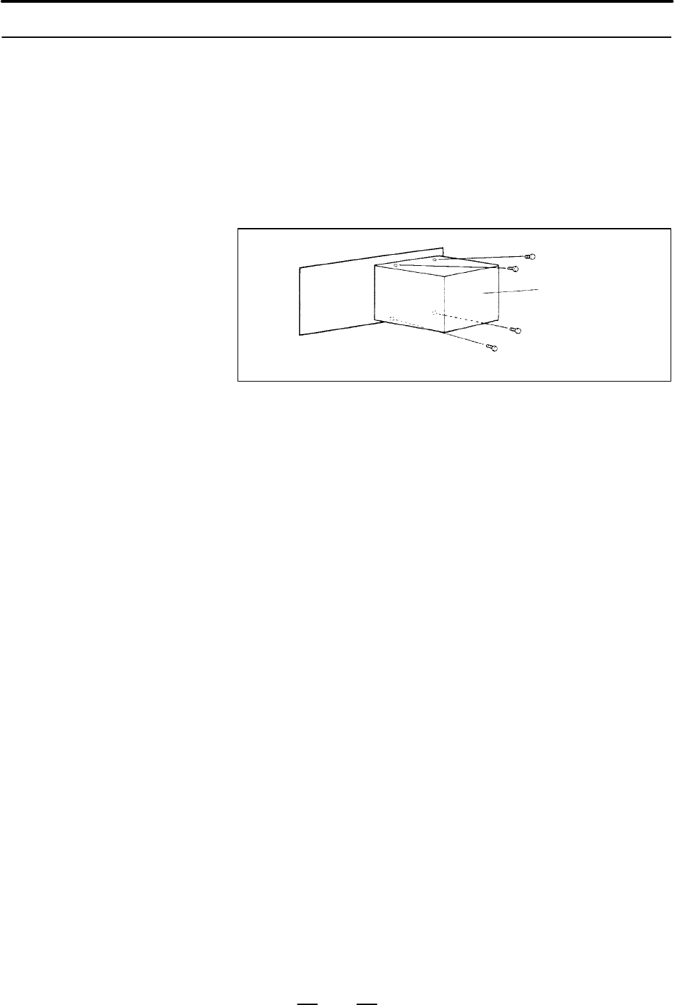
1 Check that the power supply of CRT/MDI is off.
2 Disconnect the CRT unit power cable and the video signal cable.
3 Remove the vinyl chloride cover. Then, remove the four screws
securing the CRT unit from the rear of the CRT/MDI.
4 Install the new CRT unit.
5 Reconnect the CRT power supply cable and video signal cable to their
original positions.
CRT unit
Screw
CRT/MDI
2.8.6
The CRT Unit
(CRT/MDI)
Contents Summary of POWER MATE 0 Maintenance manual
- Page 1GE Fanuc Automation Europe Computer Numerical Controls Power Mate 0 Maintenance Manual B-63445EN/01 TECHNOLOGY AND MORE�
- Page 2
- Page 3SAFETY PRECAUTIONS This section describes the safety precautions related to the use of FANUC Power Mate. It is essential that these precautions be observed by users to ensure the safe operation of machines equipped with a Power Mate (all descriptions in this section assume this configuration). Power
- Page 4SAFETY PRECAUTIONS B–63445EN/01 1 DEFINITION OF WARNING, CAUTION, AND NOTE This manual includes safety precautions for protecting the maintenance personnel (herein referred to as the use) and preventing damage to the machine. Precautions are classified into Warnings and Cautions according to their b
- Page 5B–63445EN/01 SAFETY PRECAUTIONS 2 WARNINGS, CAUTIONS, AND NOTES RELATED TO CHECK OPERATION WARNING 1. When checking the operation of the machine with the cover removed (1) The user’s clothing could become caught in the spindle or other components, thus presenting a danger of injury. When checking th
- Page 6SAFETY PRECAUTIONS B–63445EN/01 3 WARNINGS AND NOTES RELATED TO REPLACEMENT WARNING 1. Always turn off the power to the Power Mate and the main power to the power magnetics cabinet. If only the power to the Power Mate is turned off, power may continue to be supplied to the serve section. In such a c
- Page 7B–63445EN/01 SAFETY PRECAUTIONS 4 WARNINGS AND NOTES RELATED TO PARAMETERS WARNING 1. When machining a workpiece for the first time after modifying a parameter, close the machine cover. Never use the automatic operation function immediately after such a modification. Instead, confirm normal machine
- Page 8SAFETY PRECAUTIONS B–63445EN/01 5 WARNINGS RELATED TO DAILY MAINTENANCE WARNING 1. Memory backup battery replacement When replacing the memory backup batteries, keep the power to the machine (CNC) turned on, and apply an emergency stop to the machine. Because this work is performed with the power on
- Page 9B–63445EN/01 SAFETY PRECAUTIONS WARNING 2. Fuse replacement Before replacing a blown fuse, however, it is necessary to locate and remove the cause of the blown fuse. For this reason, only those personnel who have received approved safety and maintenance training may perform this work. When replacing
- Page 10B–63445EN/01 PREFACE PREFACE Description of 1.Display and operation this manual This chapter covers those items, displayed on the CRT, that are related to maintenance. A list of all supported operations (CRT or DPL) is also provided at the end of this chapter. 2.Hardware This chapter covers hardware
- Page 11PREFACE B–63445EN/01 Applicable models This manual describes following function. The models covered by this manual, and their abbreviations, are : Product Name Abbreviations FANUC Power Mate 0 Power Mate 0 Power Mate Related manuals The table below lists manuals related to the Power Mate 0. In the t
- Page 12B–63445EN/01 Table of Contents SAFETY PRECAUTIONS . . . . . . . . . . . . . . . . . . . . . . . . . . . . . . . . . . . . . . . . . . s–1 PREFACE . . . . . . . . . . . . . . . . . . . . . . . . . . . . . . . . . . . . . . . . . . . . . . . . . . . . . . . . p–1 1. DISPLAY AND OPERATION . . . . . . .
- Page 13Table of Contents B–63445EN/01 2.4.5 Location of Modules and Internal Printed Boards . . . . . . . . . . . . . . . . . . . . . . . . . . . . . . . . . . . . . . . . . 56 2.5 LIST OF PRINTED BOARD AND UNIT . . . . . . . . . . . . . . . . . . . . . . . . . . . . . . . . . . . . . . . . . . . . . 58 2.
- Page 14B–63445EN/01 Table of Contents 4.3.3 PMCDGN SCREEN . . . . . . . . . . . . . . . . . . . . . . . . . . . . . . . . . . . . . . . . . . . . . . . . . . . . . . . . . . . . . . 91 4.3.4 PMCRAM Screen . . . . . . . . . . . . . . . . . . . . . . . . . . . . . . . . . . . . . . . . . . . . . . . . . . .
- Page 15Table of Contents B–63445EN/01 7.19 ALARM 414 (DIGITAL SERVO SYSTEM IS ABNORMAL) . . . . . . . . . . . . . . . . . . . . . . . . . . . . . 167 7.20 ALARM 416 (DISCONNECTION ALARM) . . . . . . . . . . . . . . . . . . . . . . . . . . . . . . . . . . . . . . . . . . 168 7.21 ALARM 417 (DIGITAL SERVO SY
- Page 16B–63445EN/01 1. DISPLAY AND OPERATION 1 DISPLAY AND OPERATION This chapter describes how to display various screens by the function keys. The screens used for maintenance are respectively displayed. 1.1 FUNCTION KEYS AND SOFT KEYS 1.2 CONFIGURATION DISPLAY OF SOFTWARE 1.3 SYSTEM CONFIGURATION SCREEN
- Page 171. DISPLAY AND OPERATION B–63445EN/01 1.1 Operations and soft key display staturs for each function key are described below. FUNCTION KEYS AND SOFT KEYS 1.1.1 To display a more detailed screen of CRT/MDI, press a function key followed by a soft key. Soft keys are also used for actual operations. Sof
- Page 18B–63445EN/01 1. DISPLAY AND OPERATION POSITION SCREEN Soft key transition triggered by the function key POS POS Absolute coordinate display [WORK] Relative coordinate display [REL] [(OPRT)] (Axis or numeral) [PRESET] [ORIGIN] [ALLEXE] (Axis name) [EXEC] Current position display [ALL] [(OPRT)] (Axis
- Page 191. DISPLAY AND OPERATION B–63445EN/01 PROGRAM SCREEN Soft key transition triggered by the function key PROG in the MEMORY mode PROG Program display screen [PRGRM] [(OPRT)] [BG–EDT] See “When the soft key [BG–EDT] is pressed” (O number) [O SRH] (1) (N number) [N SRH] [REWIND] Program check display sc
- Page 20B–63445EN/01 1. DISPLAY AND OPERATION PROGRAM SCREEN Soft key transition triggered by the function key PROG in the EDIT mode PROG Program display [PRGRM] [(OPRT)] [BG–EDT] See “When the soft key [BG–EDT] is pressed” (O number) [O SRH] (Address) [SRH↓] (Address) [SRH↑] [REWIND] [F SRH] [CAN] (N numbe
- Page 211. DISPLAY AND OPERATION B–63445EN/01 PROGRAM SCREEN Soft key transition triggered by the function key PROG in the MDI mode PROG Program display [PRGRM] [(OPRT)] [BG–EDT] See “When the soft key [BG–EDT] is pressed” Program input screen [MDI] [(OPRT)] [BG–EDT] See “When the soft key [BG–EDT] is press
- Page 22B–63445EN/01 1. DISPLAY AND OPERATION PROGRAM SCREEN Soft key transition triggered by the function key PROG in the HANDLE/STEP, JOG or REF mode PROG Program display [PRGRM] [(OPRT)] [BG–EDT] See “When the soft key [BG–EDT] is pressed” Current block display screen [CURRNT] [(OPRT)] [BG–EDT] See “When
- Page 231. DISPLAY AND OPERATION B–63445EN/01 PROGRAM SCREEN Soft key transition triggered by the function key PROG (When the soft key [BG–EDT] is pressed in all modes) PROG Program display [PRGRM] [(OPRT)] [BG–END] (O number) [O SRH] (Address) [SRH↓] (Address) [SRH↑] [REWIND] [F SRH] [CAN] (N number) [EXEC
- Page 24B–63445EN/01 1. DISPLAY AND OPERATION OFFSET OFFSET/SETTING SCREEN Soft key transition triggered by the function key SETTING OFFSET SETTING Tool offset screen [OFFSET] [(OPRT)] (Number) [NO SRH] (Axis name) [INP.C.] (Numeral) [+INPUT] (Numeral) [INPUT] [CLEAR] [ALL] [READ] [CAN] [EXEC] [PUNCH] [CAN]
- Page 251. DISPLAY AND OPERATION B–63445EN/01 SYSTEM SCREEN Soft key transition triggered by the function key SYSTEM 1/3 SYSTEM Parameter screen [PARAM] [(OPRT)] (Number) [NO SRH] [ON:1] [OFF:0] (Numeral) [+INPUT] (Numeral) [INPUT] N , enter a file num- [READ] [CAN] To enter a file number: Press [EXEC] ber,
- Page 26B–63445EN/01 1. DISPLAY AND OPERATION (1) (2) 2/3 [PMCDGN] [TITLE] [STATUS] [SEARCH] [ALARM] [TRACE] [T.DISP]/[TRCPRM] [EXEC] [PMCPRM] [TIMER] [COUNTR] [KEEPRL] [DATA] [G.DATA] [C.DATA] [G.CONT] [G–SRCH] [NO.SRH] [SEARCH] [INIT] [STOP]/[RUN] [I/O] [EXEC] [CANCEL] (No.) [SPEED] [INPUT] [INIT] System
- Page 271. DISPLAY AND OPERATION B–63445EN/01 3/3 (1) Pitch error compensation screen [PITCH] [(OPRT)] (Number) [NO SRH] [ON:1] [OFF:0] (Numeral) [+INPUT] (Numeral) [INPUT] [READ] [CAN] To enter a file number: Press N , enter a file num- [EXEC] ber, then press , [F–SRCH], and [EXEC] on the PRGRM screen [PUN
- Page 28B–63445EN/01 1. DISPLAY AND OPERATION MESSAGE SCREEN Soft key transition triggered by the function key MESSAGE MESSAGE Alarm display screen [ALARM] Message display screen [MSG] Alarm history screen [HISTRY] [(OPRT)] [CLEAR] HELP SCREEN Soft key transition triggered by the function key HELP HELP Alar
- Page 291. DISPLAY AND OPERATION B–63445EN/01 1.1.2 DPL/MDI Function key ? Date input key œ Program edit key Input key Cursor move key Fig.1.1.2 DPL/MDI Panel (1) Function keys Function keys indicate large items like chapters in a document. Indicates the current position. Conducts the following: In EDIT mod
- Page 30B–63445EN/01 1. DISPLAY AND OPERATION Display of Alarm number and external message. (2) Keyboard functions Table 1.1.2 MDI Keyboard functions Key Functions Address /numerical key Press these keys to input alphabetic, numeric, and other characters. When an address or a numerical key is pressed, the l
- Page 311. DISPLAY AND OPERATION B–63445EN/01 1.2 CONFIGURATION DISPLAY OF SOFTWARE 1.2.1 CRT/MDI 1) Upon normal start Power Mate 883F–01 control software SERVO : 9060–01 Digital servo PMC : zzzz–zz software PMC 2) When the CRT/MDI has started normally, but cannot communicate with the controller *** INTELLI
- Page 32B–63445EN/01 1. DISPLAY AND OPERATION 1.2.2 DPL/MDI 1) Upon normal start Power Mate 0 Power Mate 883F–01 control software 2) When the DPL/MDI has started normally, but cannot communicate with the controller ROM PARI. OK RAM CHECK OK NOTE If nothing appears on the screen, it indicates that the DPL/MD
- Page 331. DISPLAY AND OPERATION B–63445EN/01 1.3 Once the system has stared up normally, you can display a system configuration screen to know the types of mounted PCBs or the type of SYSTEM installed software. When a DPL/MDI is used, however, you cannot CONFIGURATION display a system configuration screen.
- Page 34B–63445EN/01 1. DISPLAY AND OPERATION 1.3.3 Configuration of the modules displayed on PCB. Module Configuration Screen SYSTEM CONFIG(MODULE) MODULE TYPE RAM 256KB 2.5MB ___ PMC BIT SCA (CRT) 9”CRT SERVO 1/2 MOUNTED (2) POS LSI MOUNTED (SUB BOARD BUILT IN I/O) Information of sub PCB (1) EDIT **** ***
- Page 351. DISPLAY AND OPERATION B–63445EN/01 1.4 ALARM HISTORY SCREEN 1.4.1 Alarms generated in the Power Mate are recorded. The latest 25 alarms generated are recorded. The 26th and former alarms are deleted. General DPL/MDI can not display the alarm history screen. 1.4.2 Screen Display (1) Press MESSAGE
- Page 36B–63445EN/01 1. DISPLAY AND OPERATION 1.5 HELP FUNCTION 1.5.1 General The help function displays alarm information, operation method and a table of contents for parameters. This function is used as a handbook. DPL/MDI can not use the help function. 1.5.2 Display Method D Display of help screen Press
- Page 371. DISPLAY AND OPERATION B–63445EN/01 D Help for operation (1) Press [2 OPR], then a menu for operation method is displayed. HELP (OPERATION METHOD) O1234 N12345 1. PROGRAM EDIT 2. SEARCH 3. RESET 4. DATA INPUT WITH MDI 5. DATA INPUT WITH TAPE 6. OUTPUT 7. INPUT WITH FANUC CASSETTE 8. OUTPUT WITH FA
- Page 38B–63445EN/01 1. DISPLAY AND OPERATION D Parameter table Press soft key [3 PARA], then a parameter table is displayed. HELP (PARAMETER TABLE) O1234 N12345 1/3 Current page/ Total ·SETTING (NO.0000~ ) page ·READER/PUNCHER INTERFACE (NO.0100~ ) ·AXIS CONTROL/SETTING UNIT (NO.1000~ ) ·COORDINATE SYSTEM
- Page 391. DISPLAY AND OPERATION B–63445EN/01 1.6 DISPLAYING DIAGNOSTIC PAGE 1.6.1 Displaying of CRT/MDI (1) Press SYSTEM key on the CRT/MDI. (2) Press soft key [DGN], then a diagnostic screen is displayed. 1.6.2 Displaying of DPL/MDI (1) Press the key to select the diagnosis screen. When PMC data is displa
- Page 40B–63445EN/01 1. DISPLAY AND OPERATION 1.6.3 Contents Displayed (Common) D Causes when the 000 WAITING FOR FIN SIGNAL An miscelaneous function is machine does not travel being executed. in spite of giving a 001 MOTION Travel command of cycle command operation is being executed. 002 DWELL Dwell is bei
- Page 411. DISPLAY AND OPERATION B–63445EN/01 D Details of digital servo alarm 414 Address #7 #6 #5 #4 #3 #2 #1 #0 DGN 200 OVL LV OVC HCA HVA DCA FBA OFA #7(OVL): Overload alarm (Refer to DGN 201) #6(LV) : Insufficient voltage alarm #5(OVC): Over current alarm #4(HCA): Abnormal current alarm #3(HVA): Overvo
- Page 42B–63445EN/01 1. DISPLAY AND OPERATION D Position error amount Address DGN 0300 Position error of an axis in detection unit Feed rate [mm/min] _ 1 Position error= 60 servo loop gain [1/sec] Detection unit D Machine position Address DGN 0301 Distance from reference position of an axis in detection uni
- Page 431. DISPLAY AND OPERATION B–63445EN/01 831 Actual feedrate Unit: mm/min, deg/min, or 0.01 inch/min 832 Actual spindle speed Unit: rpm 840 Number of registered blocks Unit: Blocks 841 Amount of memory used by Unit: Characters program 850 ROM series No. of NC system (Example) 883F 851 ROM version No. o
- Page 44B–63445EN/01 1. DISPLAY AND OPERATION 1.7 See the diagnostic screen for the DPL/MDI. POWER MATE STATE DISPLAY ACTUAL POSITION (ABSOLUTE) O1000 N00010 X 217.940 Z 363.233 ACT.F 3000MM/M MDI STRT MTN *** [ ABS ] [ REL ] [ ALL ] [ HNDL ] [ OPRT ] MDI STRT MTN *** ALM/BAT (Alarm state/ Low battery) FIN
- Page 451. DISPLAY AND OPERATION B–63445EN/01 1.8 This function displays the key and signal operations performed by the NC operator upon the occurrence of a fault or the output of an NC alarm, OPERATION HISTORY together with the corresponding NC alarms. Operation history information cannot be displayed on t
- Page 46B–63445EN/01 1. DISPLAY AND OPERATION These soft keys can also be used: 1) Pressing the [TOP] soft key displays the first page (oldest data). 2) Pressing the [BOTTOM] soft key displays the last page (latest data). 3) Pressing the [PG.SRH] soft key displays a specified page. Example) By entering 50 t
- Page 471. DISPLAY AND OPERATION B–63445EN/01 Mode selection signals and rapid traverse override signals are displayed as indicated below: Input signal Name displayed MD1 ND2 MD4 ZRN DNCI 0 0 0 0 0 MDI 1 0 0 0 0 MEM 1 0 0 0 1 RMT 0 1 0 0 0 NOMODE 1 1 0 0 0 EDT 0 0 1 0 0 H/INC 1 0 1 0 0 JOG 1 0 1 1 0 ZRN Inp
- Page 48B–63445EN/01 1. DISPLAY AND OPERATION D Input signal or output (1) P ress the SYSTEM function key. signal to be recorded in the operation history (2) Press the continue menu key . The [OPEHIS] (operation history) soft key is displayed. (3) Press the [OPEHIS] soft key, then press the [SG–SEL] soft ke
- Page 491. DISPLAY AND OPERATION B–63445EN/01 (4) Select the bit to be recorded. To select all bits of the specified signal address, press the [ON:1] soft key while the cursor is positioned to 00000000 . To select a particular bit, position the cursor to that bit by pressing the cursor key or , then press t
- Page 50B–63445EN/01 1. DISPLAY AND OPERATION 1. Addresses list MT→PMC #7 #6 #5 #4 #3 #2 #1 #0 X000 f f f f f f f f ∼∼ X127 f f f f f f f f PMC→CNC #7 #6 #5 #4 #3 #2 #1 #0 G000 f f f f f f f f ∼∼ G003 f f f f f f f f G004 f f f f FIN f f f G005 f f f f TFIN SFIN f MFIN G006 f f f f f *ABS f f G007 f f *FLUP
- Page 511. DISPLAY AND OPERATION B–63445EN/01 #7 #6 #5 #4 #3 #2 #1 #0 G101 f f f f f f f f G102 f f f f f f –J2 –J1 G103 f f f f f f f f ∼∼ G105 f f f f f f f f G106 f f f f f f MI2 MI1 G107 f f f f f f f f G108 f f f f f f MLK2 MLK1 G109 f f f f f f f f G110 f f f f f f f f G111 f f f f f f f f G112 f f f
- Page 52B–63445EN/01 1. DISPLAY AND OPERATION PMC→MT #7 #6 #5 #4 #3 #2 #1 #0 Y000 f f f f f f f f ∼∼ Y127 f f f f f f f f CNC→PMC #7 #6 #5 #4 #3 #2 #1 #0 F000 f f f f f f f f ∼∼ F255 f f f f f f f f 1.8.3 Notes (1) While the operation history screen is displayed, no information can be recorded to the histor
- Page 531. DISPLAY AND OPERATION B–63445EN/01 1.9 LIST OF OPERATIONS (CRT/MDI) Classifi- Function KEY SETTING Mode Function Operation cation SW PWE = 1 key Reset Resetting the OT When the _ and alarm power is on Resetting alarm 100 _ _ and Data in- Inputting parameters f MDI or emer- SYSTEM Parameter No. →
- Page 54B–63445EN/01 1. DISPLAY AND OPERATION Classifi- Function KEY SETTING Mode Function Operation cation SW PWE = 1 key Search Searching for a MEMORY or PROG → Program No. → [O SRH] program number EDIT Searching for a MEMORY PROG Program No. search → → sequence number Sequence No. → [N SRH] Searching for
- Page 551. DISPLAY AND OPERATION B–63445EN/01 Classifi- Function KEY SETTING Mode Function Operation cation SW PWE = 1 key Input/ Outputting all the EDIT PROG → –9999 → [ ] → [PUNCH] → output to/ programs [EXEC] from the FANUC Outputting one EDIT PROG → Program No. → [ ] → [PUNCH] → Cassette program [EXEC]
- Page 56B–63445EN/01 1. DISPLAY AND OPERATION 1.10 LIST OF OPERATION (DPL/MDI) Classifi- Function KEY SETTING Mode Function Operation cation SW PWE = 1 key Clear All memory clear Power ON __ AND Parameter/offset clear f Power ON __ Program clear f Power ON __ Alarm clear __ __ or Power OFF/ON Alarm P/S101 c
- Page 571. DISPLAY AND OPERATION B–63445EN/01 Classifi- Function KEY SETTING Mode Function Operation cation SW PWE = 1 key Editing All program delete f EDIT → –9999 → One program delete f EDIT → Program number → Multiple block delete f EDIT → Sequence number → One block delete f EDIT → Word delete f EDIT Se
- Page 58B–63445EN/01 1. DISPLAY AND OPERATION Classifi- Function KEY SETTING Mode Function Operation cation SW PWE = 1 key Input/out- Program registration f EDIT → File number → → put to and from All program output EDIT → –9999 → FANUC Handy File One program output EDIT → Program number → Search for beginni
- Page 592. HARDWARE B–63445EN/01 2 HARDWARE This chapter describes structure of CNC control section, connection of units and the functions of PCBs and modules mounted on PCBs. 2.1 TOTAL CONNECTION DIAGRAM 2.2 INSTALLATION 2.3 CONNECTOR LAYOUT OF CONTROL UNIT 2.4 LED DISPLAY/SETTING AND MODULE CONFIGURATION
- Page 60B–63445EN/01 2. HARDWARE 2.1 TOTAL CONNECTION DIAGRAM Power supply P.C. board +24VDC power supply Base P.C. board Battery 3V for RAM battery backup Memory card Emergency stop 1st axis servo amplifier 100VAC, 1φ 200VAC, 3φ 1st axis servo motor (Built–in type serial pulse coder) 2nd axis servo amplifi
- Page 612. HARDWARE B–63445EN/01 2.2 INSTALLATION 2.2.1 The peripheral units, such as the control unit and CRT/MDI, have been Environmental designed on the assumption that they are housed in closed cabinets. In this manual ”cabinet” refers to the following: Requirement D Cabinet for housing the control unit
- Page 62B–63445EN/01 2. HARDWARE 2.2.3 The CNC has been steadily reduced in size using surface–mount and Action Against Noise custom LSI technologies for electronic components. The CNC also is designed to be protected from external noise. However, it is difficult to measure the level and frequency of noise
- Page 632. HARDWARE B–63445EN/01 NOTE 1 The groups must be 100mm or more apart from one another when binding the cables in each group. 2 The electromagnetic shield refers to shielding between groups with grounded steel plates. Cabinet Servo Spindle Control amp. amp. unit Cable of group B, C Duct To operator
- Page 64B–63445EN/01 2. HARDWARE D Connecting the Frame Connect the 0 V line of the electronic circuit in the control unit with the Ground (FG) of the ground plate of the cabinet via the ground (FG) terminal for signal. Control Unit Cabinet Air goes out. Air comes in. FG terminals (Faston terminals at the c
- Page 652. HARDWARE B–63445EN/01 D Noise Suppressor The AC/DC solenoid and relay are used in the power magnetics cabinet. A high pulse voltage is caused by coil inductance when these devices are turned on or off. This pulse voltage induced through the cable causes the electronic circuits to be disturbed. No
- Page 66B–63445EN/01 2. HARDWARE D Diode is used for direct–current circuits – + Diode Use a diode which can withstand a voltage up to two times the applied DC relay voltage and a current up to two times the applied current. D Cable Clamp and Shield The power motion controller cables that require shielding
- Page 672. HARDWARE B–63445EN/01 ÇÇ Machine side installation Control unit ÇÇ board ÇÇ ÇÇ ÇÇ ÇÇ ÇÇ ÇÇ ÇÇ ÇÇ ÇÇ Ground plate ÇÇ ÇÇ ÇÇ Metal fittings ÇÇ ÇÇ for clamp Shield cover Cable clamp (2) 52
- Page 68B–63445EN/01 2. HARDWARE 2.3 CONNECTOR LAYOUT OF CONTROL UNIT Front Bottom face Fuse (5.0A) Left side M4 DPL/MDI CB 128 Memory card Built–in I/O +24VDC input Right side CB 129 Built–in I/O TEST Servo check LED display Rotary switch JD15 CRT/MDI Terminal resistant Servo amplifier (1st axis) unit Unus
- Page 692. HARDWARE B–63445EN/01 2.4 LED DISPLAY/ SETTING AND MODULE CONFIGURATION OF UNIT 2.4.1 LED Display of Control If an alarm occurred, an alarm message is usually displayed on the screen Unit of setting and display unit. However, it is possible that no alarm appears, if the display function is in tro
- Page 70B–63445EN/01 2. HARDWARE 2.4.4 For the Power Mate 0, leave rotary switch RSW set to 0. Setting the Rotary Also, leave rotary switch MTSW set to 0. Normally, do not set other number except [0]. Switch RSW 55
- Page 712. HARDWARE B–63445EN/01 2.4.5 Location of Modules and Internal Printed Boards NAME NUMBER USE Memory card CNMC Memory card (4) S1 S0 LED WD EN LED display Rotary switch RSW Unused Rotary switch MTSW Unused AMP1 JS1 Servo amplifier (1st axis) (1) F01 (3) (6) SCALE1 JF21 Unused AMP2 JS2 Servo amplifi
- Page 72B–63445EN/01 2. HARDWARE Display of system con- No. NAME Specification Function figuration screen Base PCB A20B–2100–0160 RAM 256KB RAM 256KB Servo function SERVO 1/2 Servo interface (1) PMC controled module A A20B–2900–0142 PMC–PA1 PMC BIT (2) Analog spindle module A20B–2902–0235 Analog spindle POS
- Page 732. HARDWARE B–63445EN/01 2.5 LIST OF PRINTED BOARD AND UNIT 2.5.1 Basic Unit NAME Specification Servo Remarks interface Power Mate 0 Basic unit A02B–0166–B591 TYPE B 2.5.2 Control Unit Printed Board NAME Specification Remarks Base PCB A16B–2100–0160 TYPE B Power supply PCB A20B–1004–0960 2.5.3 Modul
- Page 74B–63445EN/01 2. HARDWARE 2.6 HOW TO REPLACE THE BATTERIES WARNING Memory backup battery replacement When replacing the memory backup batteries, keep the power to the machine (CNC) switched on, and hold the machine at an emergency stop. Because this work must be carried out while the power is kept sw
- Page 752. HARDWARE B–63445EN/01 Control unit front panel ÂÂ Battery Battry (ordering infomation : A02B–0118 K111) BATTERY Connector on the cable Connector on the printed circuit board Battery Control unit 60
- Page 76B–63445EN/01 2. HARDWARE 2.7 HOW TO REPLACE THE MODULES 2.7.1 1 Check that the power supply is not off. Removing 2 Pull the latches of the module socket outwards. (Fig.(a)) 3 Pull out the module upward. (Fig.(b)) 2.7.2 1 Check that the power supply is off. Insertion 2 Insert the new module board dia
- Page 772. HARDWARE B–63445EN/01 2.8 REPLACING PRINTED CIRCUIT BOARD AND UNIT 2.8.1 1 Make sure that the power supply unit is turned off. The Base Printed 2 Disconnect all cables connected to the control unit. Pinch the 20–pin half–pitch connector to release the latch. Draw out the connector. Circuit Boards
- Page 78B–63445EN/01 2. HARDWARE How to remove the plastic cover at the left side of the case How to remove the base printed circuit board D Pull the cover in the direction of arrows as shown D Remove the lithium battery for backing up the SRAM. below while holding down two portions marked with D There are
- Page 792. HARDWARE B–63445EN/01 2.8.3 The Fan motor 1 Remove the power PC board as in 2.8.2 above. 2 Remove the two screws from the fan motor on the power PC board, and replace the fan motor with a new one. 3 Mount the power PC board on the base PC board as in 2.8.2 above, and return the base PC board to t
- Page 80B–63445EN/01 2. HARDWARE 2.8.6 The CRT Unit 1 Check that the power supply of CRT/MDI is off. (CRT/MDI) 2 Disconnect the CRT unit power cable and the video signal cable. 3 Remove the vinyl chloride cover. Then, remove the four screws securing the CRT unit from the rear of the CRT/MDI. 4 Install the n
- Page 812. HARDWARE B–63445EN/01 2.9 REPLACING THE FUSE WARNING Before replacing a blown fuse, it is necessary to remove the cause of the blown fuse. For this reason, only the personnel who have a working knowledge of maintenance and safety are allowed to carry out this work. When replacing a fuse with the
- Page 82B–63445EN/01 2. HARDWARE 2.9.2 This section describes the replacement of the CRT controll PCB fuse of The CRT/MDI Control the Power Mate 0. The table below lists the drawing number of the CRT control PCB. The CRT control PCB is mounted on the back of the PCB Fuse CRT/MDI. Table 2.9.2(a) CRT control
- Page 833. INPUT AND OUTPUT OF DATA B–63445EN/01 3 INPUT AND OUTPUT OF DATA Data must be reset after the base PCB is replaced or all the memory is cleared. This chapter describes how to input and output data including parameters, part programs, and tool compensation values using an external I/O device such
- Page 84B–63445EN/01 3. INPUT AND OUTPUT OF DATA 3.1 SETTING PARAMETERS FOR INPUT/OUTPUT D Setting procedure of First, perform steps 1 to 3 below to enable parameter setting. parameters (CRT/MDI) 1. Set to MDI mode or emergency stop state. 2. Press key several times or press soft key [SETING] to display SET
- Page 853. INPUT AND OUTPUT OF DATA B–63445EN/01 7. Convenient method 1) To change parameters in bit unit, press cursor key or ,then the cursor becomes bit length and you can set parameters bit by bit (Bit parameter only). 2) To set data consecutively, use EOB key. (Ex.1) 0 1234 0 ⇒ 4567 0 9999 0 0 (Ex.2) 0
- Page 86B–63445EN/01 3. INPUT AND OUTPUT OF DATA D Setting parameters 1. Set MDI mode or emergency stop. procedare (DPL/MDI) 2. Press the key to display the settings screen. 3. Use the cursor keys to position the cursor at PWE, then press the key and the key, in that order, to enable parameters to be writte
- Page 873. INPUT AND OUTPUT OF DATA B–63445EN/01 3.2 Power Mate memorized the following data. Outputting the newest data flash memory card or I/O device while the INPUTTING/ CNC is rurnning normally OUTPUTTING DATA (1) CNC paramter (2) PMC parameter (3) Custom macro variable values (4) Tool compensation amo
- Page 88B–63445EN/01 3. INPUT AND OUTPUT OF DATA Address 0103 Baud Rate 7: 600 9: 2400 11:9600 8: 1200 l10: 4800 12:19200 [BPS] 2) I/O cahnnel=1 Set parameters to 0111, 0112, 0113. Seeting contens are same as 0101, 0102, 0103. 3.2.2 Outputting CNC Parameters D Procedure (CRT/MDI) 1. Select EDIT mode. 2. Exe
- Page 893. INPUT AND OUTPUT OF DATA B–63445EN/01 3.2.3 Outputting PMC Parameters D Procedure (CRT/MDI) 1. Select MDI mode. 2. Press OFFSET SETTING key then soft key [SETTING] to select a setting screen. 3. Set the cursor to PARAMETER WRITE and input and . At this time, alarm 100 will be generated. 4. Press
- Page 90B–63445EN/01 3. INPUT AND OUTPUT OF DATA 7. Select EDIT (editing) mode. 8. Display the PMC parameter press key then set file number. 9. Press . Then PMC parameters are started to be output. 10.After the PMC parameters have been output, set PWE to 0. 11.Reset Power Mate to release alarm 100. 3.2.4 Ou
- Page 913. INPUT AND OUTPUT OF DATA B–63445EN/01 D Procedure (DPL/MDI) 1. Select EDIT mode. 2. Select the offset data display screen by pressing key. 3. Press the key. 4. While offset, is being output, the display appears as below. 0. 0 0 0 WRITE T001X= 5. In order to stop output of data from a tape before
- Page 92B–63445EN/01 3. INPUT AND OUTPUT OF DATA 3.2.7 Outputting Ladder Programs D Procedure (CRT/MDI) 1. Select MDI mode. 2. Press OFFSET SETTING key then soft key [SETTING] to select a setting screen. 3. Set the cursor to PARAMETER WRITE and input and . At this time, alarm 100 will be generated. 4. Press
- Page 933. INPUT AND OUTPUT OF DATA B–63445EN/01 3.2.8 Outputting Pitch Error Compensation Value Procedure (CRT/MDI) 1 Select EDIT (editing) mode. 2 Press function key SYSTEM . 3 Press the rightmost soft key (next–menu key) and press chapter selection soft key [PITCH]. 4 Press soft key [(OPRT)]. 5 Press rig
- Page 94B–63445EN/01 3. INPUT AND OUTPUT OF DATA 3.2.10 Inputting PMC Parameters D Procedure (CRT/MDI) 1. Set the emergency stop state. 2. Press OFFSET SETTING key and soft key [SETTING] to select the SETTING screen. 3. Confirm that PARAMETER WRITE=1. 4. Press SYSTEM key and soft key [PMC]. 5. Press soft ke
- Page 953. INPUT AND OUTPUT OF DATA B–63445EN/01 3.2.11 Inputting Custom Macro Variable Values D Procedure (CRT/MDI) 1. Select EDIT (editing) mode. 2. Turn off the program protect key (KEY2=1). 3. Press PROG key then soft key [PRGRM] to display program contents. 4. Press soft key [(OPRT)] and key . 5. Press
- Page 96B–63445EN/01 3. INPUT AND OUTPUT OF DATA 4. Press OFFSET SETTING key, and soft key [OFFSET] to display the tool compensation amount screen. 5. Press soft key [(OPRT)] and key. 6. Press [READ] key and [EXEC] key and data input is started. D Procedure (DPL/MDI) 1. Select the EDIT (editing) mode. 2. Di
- Page 973. INPUT AND OUTPUT OF DATA B–63445EN/01 3. When the controller tape does not have a program number or a program number is to be changed, enter a desired program number. (When the controller tape has a program number and a program number is not changed, this operation is not necessary.) i) Key in ad
- Page 98B–63445EN/01 3. INPUT AND OUTPUT OF DATA 3.2.15 Inputting Pitch Error Compensation Value Procedure (CRT/MDI) 1. Make sure the input device is ready for reading. 2. Set to the emergency stop state. 3. Press OFFSET SETTING key. 4. Press the soft key [SETING] for chapter selection. 5. Enter 1 in respon
- Page 994. INTERFACE BETWEEN NC AND PMC B–63445EN/01 4 INTERFACE BETWEEN NC AND PMC This chapter describes the signals between the machine operator’s panel, magnetics cabinet and the PMC, connection of the signals between PMC and CNC, and confirmation method of on/off state of these signals. The chapter als
- Page 1004.1 GENERAL OF B–63445EN/01 PMCDGN Input Contacts HIgh–speed processing signal [0] ...0V Open *DEC a, *ESP,SKIP [1] ...24V Close INTERFACE PMCDGN PMCDGN * NC PMC DI/DO MT (Machine Tool builder) X1000 to G0000 to 0255 1003 ST1 DOOR ST G X RV ST1 X1000.1 X1000.0 G007.2 ST2 ST2 0V X1000.7 +24E + STL ST
- Page 1014. INTERFACE BETWEEN NC AND PMC B–63445EN/01 4.2 SPECIFICATION OF PMC 4.2.1 Model PMC–PA1 Specification Programming method language Ladder Number of ladder level 2 Level–1 Cycle Time 8 ms Basic Instruction Execution Time 4.5 (µs/step) Program capacity S Ladder (step) Approx. 3,000 S Symbol/comment (
- Page 102B–63445EN/01 4.INTERFACE BETWEEN NC AND PMC 4.2.2 Address Type Byte Address Explanation G PMC⇒CNC 256 G000.0 to G255.7 F CNC⇒PMC 256 F000.0 to F255.7 Y PMC⇒MT 3 Y1000.0 to Y1002.7 Built–in I/O card X MT⇒PMC 4 X1000.0 to X1003.7 Built–in I/O card A Massege display 25 A000.0 to A024.7 R Internal relay
- Page 1034. INTERFACE BETWEEN NC AND PMC B–63445EN/01 4.2.4 System Reserve Area #7 #6 #5 #4 #3 #2 #1 #0 of Internal Relay R9000 V N Z Operation result register Zero Sign is minus Overflow #7 #6 #5 #4 #3 #2 #1 #0 R9002 R9003 Register for remainder R9004 (used by DIVB instruction) R9005 4.2.5 At the first leve
- Page 104B–63445EN/01 4.INTERFACE BETWEEN NC AND PMC 4.3 OPERATION ON THE CRT/MDI 4.3.1 1. Press SYSTEM . Display Method 2. Press soft key [PMC], then PMC screen is displayed and the following soft keys are displayed: PMC CONTROL SYSTEM MENU MONIT RUN SELECT ONE OF FOLLOWING SOFT KEYS PMCLAD : DYNAMIC LADDER
- Page 1054. INTERFACE BETWEEN NC AND PMC B–63445EN/01 4.3.2 Press soft key [PMCLAD], and a sequence program is displayed PMCLAD SCREEN dynamically and operation monitoring can be confirmed : Number of net displayed Ladder display RUN/STOP status LADDER NET 0001–0004 MONIT RUN Comment LOG1 LOG1 ALWAYS1 LOG1 X
- Page 106B–63445EN/01 4.INTERFACE BETWEEN NC AND PMC 4.3.3 Press soft key [PMCDGN] then PMC’s diagnostic screen is displayed. PMCDGN SCREEN D TITLE screen The title data registered when a ladder program is prepared is displayed. Page number PMC TITLE DATA #1 MONIT RUN PMC PROGRAM NO. : EDITION NO. : PMC CONT
- Page 1074. INTERFACE BETWEEN NC AND PMC B–63445EN/01 D STATUS screen On/Off state of input/output signals and internal relay is displayed. PMC SIGNAL STATUS MONIT RUN ADDRESS 7 6 5 4 3 2 1 0 FIN Signal G0004 0 0 0 0 1 0 1 0 name Signal state G0005 0 0 0 0 0 0 0 0 0:Off 1:On G0006 0 0 0 0 0 0 0 0 Signal stat
- Page 108B–63445EN/01 4.INTERFACE BETWEEN NC AND PMC D TRACE screen Every time a specified signal changes, the signal status is memorized in the trace memory. This function is useful for identifying intermittent troubles. (1) Trace parameter screen PMC SIGNAL TRACE MONIT RUN TRACE MODE : (0:1BYTE/1:2BYTE/2:W
- Page 1094. INTERFACE BETWEEN NC AND PMC B–63445EN/01 (2) Trace memory contents display screen PMC SIGNAL TRACE MONIT RUN 1ST ADDRESS=R008(E1) 2ND ADDRESS=G000(FF) Trace address NO. 7 6 5 4 3 2 1 0 7 6 5 4 3 2 1 0 and mask 0000 . . . . . . . . . . . . . . . . data 0001 I * * * * * * * * * * * * * * * 0002 I
- Page 110B–63445EN/01 4.INTERFACE BETWEEN NC AND PMC 4.3.4 PMCRAM Screen D Inputting PMC parameters from the MDI (1) Set to MDI mode or emergency stop state. (2) Set PARAMETER WRITE (on setting screen) to 1 or set the program protect signal (KEY4) to 1. PWE KEY4 Timer f – counter f f Either one Keep relay f
- Page 1114. INTERFACE BETWEEN NC AND PMC B–63445EN/01 D COUNTER screen This screen sets and displays max. value of counter and current value of the counter instruction (SUB 4). Page no. (screen is scrolled by page key) Max. value of counter (Minimum value is specified by counter ins.) Current value of counte
- Page 112B–63445EN/01 4.INTERFACE BETWEEN NC AND PMC (1) Nonvolatile memory control Address #7 #6 #5 #4 #3 #2 #1 #0 k016 #7(MWRTF2): For checking the writing status in nonvolatile memory #6(MWRTF1): Writing status in nonvolatile memory (2) PMC system parameter The following keep relays are used by the system
- Page 1134. INTERFACE BETWEEN NC AND PMC B–63445EN/01 D DATA TABLE screen (1) Data table control data screen No. of screen PMC DATA TBL CONTROL #001 MONIT RUN GROUP TABLE COUNT = 2 No. of data table NO. ADDRESS PARAMETER TYPE NO.OF DATA groups 001 D0000 00000000 0 10 002 D0020 00000011 1 20 003 004 No. of 00
- Page 114B–63445EN/01 4.INTERFACE BETWEEN NC AND PMC (2) Data table screen Group number Page number PMC PRM (DATA) 001/001 MONIT RUN NO. ADDRESS DATA 000 D0000 0 001 D0001 0 002 D0002 0 003 D0003 0 004 D0004 0 005 D0005 0 006 D0006 0 007 D0007 0 008 D0008 0 009 D0009 0 C.DATA G–SRCH SEARCH a. Soft key [C.DAT
- Page 1154. INTERFACE BETWEEN NC AND PMC B–63445EN/01 4.4 The DPL/MDI panel is used to set PMC system parameters and create and execute the sequence program. OPERATION ON THE (1) Setting and displaying PMC system parameters (SYSTEM PARAM) DPL/MDI – The type of counter data (BCD or binary) can be selected. (2
- Page 116B–63445EN/01 4.INTERFACE BETWEEN NC AND PMC The screen configuration for the PMC programmer (DPL/MDI) function is as follows: PMC programmer menu Sequence program start and stop or PMC PRG MENU 1/3 LADDER RUN/STOP >RUN/STOP MONITOR (STOP) or PMC editing menu Editing ladder mnemonics or or PMC PRG ME
- Page 1174. INTERFACE BETWEEN NC AND PMC B–63445EN/01 Current Position screen Program screen PMC programmer screen (K17#1=1) (PMC programmer menu) (PMC editing menu) Alarm/Message screen Parameter/Diagnostic screen Offset/Setting/Macro Variable screen 4.4.2 Selecting SYSTEM PARAM on the PMC programmer menu d
- Page 118B–63445EN/01 4.INTERFACE BETWEEN NC AND PMC 4.4.3 Selecting EDIT on the PMC programmer menu displays the editing Editing the Sequence menu. Program (Edit) 1 Display the PMC programmer menu. 2 Display the EDIT item by pressing the or key. PMC PRG MENU 2/3 >EDIT 3 Press the or key. The PMC editing men
- Page 1194. INTERFACE BETWEEN NC AND PMC B–63445EN/01 N0123 SUB 50 PSGNL 3 Relay search Entering then searches for the relay including the entered address. (Example) , N0105 AND X1000.2 4 Relay coil search Entering , , then searches for the relay coil including the entered ad
- Page 120B–63445EN/01 4.INTERFACE BETWEEN NC AND PMC (3) Modifying the ladder mnemonics 1 Changing an instruction (a) Display the instruction to be changed. (b) Enter a new instruction. (c) Press the key. (Example) , , N1234 AND R0123.4 Before change N1234 OR Y1001.4 After change NOTE If changing the instruc
- Page 1214. INTERFACE BETWEEN NC AND PMC B–63445EN/01 4 Deleting the ladder program (a) Enter . (b) Press the key. The whole ladder program is deleted. (4) Ending ladder mnemonics editing 1 Press the or key. 2 ”EXECUTING” is displayed. N0001 EXECUTING 3 The PMC editing menu appears. NOTE 1 If the sequence pr
- Page 122B–63445EN/01 4.INTERFACE BETWEEN NC AND PMC 4.4.5 Selecting RUN/STOP on the PMC programmer menu displays the Starting and Stopping sequence program start/stop screen. the Sequence Program 1 Display the PMC programmer menu. (Run/Stop) 2 Display the RUN/STOP item by pressing the or key. PMC PRG MENU 1
- Page 1234. INTERFACE BETWEEN NC AND PMC B–63445EN/01 4.5 LIST OF SIGNALS BY EACH MODE D Automatic operation MODE INPUT/OUTPUT SIGNAL FEED RATE, ETC EDIT [PMC ⇒ CNC] KEY3(Program protect key) [PMC ⇒ CNC] [PMC ⇒ CNC] ST (Cycle start) *FV0 to 7 *SP (Feed hold) (Feed rate over- A SBK (Single block) ride) U DRN
- Page 124B–63445EN/01 4.INTERFACE BETWEEN NC AND PMC D Others [PMC ⇒ CNC] MD1 to 4 (Mode selection) *ESP (Emergency stop) KEY1 to 4(Memory protection key) MLK (All axes machine lock) *IT,*ITα (All axes each axis machine lock) *ABSM (Manual absolute) SVFα (Servo off) *FLWP (Follow up) ERS (External reset) Oth
- Page 1254. INTERFACE BETWEEN NC AND PMC B–63445EN/01 4.6 Address of interface signal between CNC and PMC. ADDRESS LIST CNC PMC MT G000 or X1000 or later later F000 or Y1000 or later later 4.6.1 Power Mate–D for 1–path Control MT ³ PMC Address Bit No. #7 #6 #5 #4 #3 #2 #1 #0 X1000 SKIP *DEC1 *ESP X1001 *DEC2
- Page 126B–63445EN/01 4.INTERFACE BETWEEN NC AND PMC PMC ³ CNC Address Bit No. #7 #6 #5 #4 #3 #2 #1 #0 G004 FIN G005 AFL TFIN SFIN MFIN G006 OVC *ABSM G007 *FLWU ST G008 ERS RRW *SP *ESP *IT G009 PN3 PN2 PN1 PN0 G010 *JV7 *JV6 *JV5 *JV4 *JV3 *JV2 *JV1 *JV0 G011 *JV15 *JV14 *JV13 *JV12 *JV11 *JV10 *JV9 *JV8 G
- Page 1274. INTERFACE BETWEEN NC AND PMC B–63445EN/01 CNC ³ PMC Address Bit No. #7 #6 #5 #4 #3 #2 #1 #0 F000 OP SA STL SPL RWD F001 MA ENB DEN BAL RST AL F002 CUT THRD CSS F003 MEDT MMEM MRMT MMDI MJ MH F004 MZRN F007 TF SF MF F010 M07 M06 M05 M04 M03 M02 M01 M00 F011 M15 M14 M13 M12 M11 M10 M09 M08 F012 M23
- Page 128B–63445EN/01 4.INTERFACE BETWEEN NC AND PMC Address Bit No. #7 #6 #5 #4 #3 #2 #1 #0 F072 OUT7 OUT6 OUT5 OUT4 OUT3 OUT2 OUT1 OUT0 F073 ZRNO MD4O MD2O MD1O F075 *SPO KEYO DRNO MLKO SBKO BDTO F076 ROV2O ROV1O MP2O MP1O F077 RTO HS1BO HS1AO F078 *FV7O *FV6O *FV5O *FV4O *FV3O *FV2O *FV1O *FV0O F079 *JV7O
- Page 1294. INTERFACE BETWEEN NC AND PMC B–63445EN/01 4.7 SIGNAL AND SYMBOL CORRESPONDENCE TABLE Symbol Signal name PMC address :ABSM Manual absolute signal G006#2 AFL Auxiliary function lock signal G005#6 AL CNC alarm signal F001#0 BAL Battery alarm signal F001#2 BDT Optional block skip signal G044#0 BDTO O
- Page 130B–63445EN/01 4.INTERFACE BETWEEN NC AND PMC Symbol Signal name PMC address +J1, +J2, –J1, –J2 Feed axis direction select signal G100#0, #1, G102#0, #1 +J1O, –J1O, +J2O, Manual feed F081#0 to #3 –J2O : JV0 to :JV15 Manual feedrate override signal G010, G011 : JV0O to :JV15O Jog feedrate setting signa
- Page 1314. INTERFACE BETWEEN NC AND PMC B–63445EN/01 Symbol Signal name PMC address OUT0 to OUT7 Software operator’s panel general purpose switch signal F072 OVC Override cancel signal G006#4 PN0 to PN3 Workpiece number search signal G009 ROV1, ROV2 Rapid traverse override signal G014#0, #1 ROV1O, ROV2O Rap
- Page 132B–63445EN/01 4.INTERFACE BETWEEN NC AND PMC Symbol Signal name PMC address ZRN Manual reference position return selection signal G043#7 ZRNO Reference position return signal (software operator’s panel) F073#4 117
- Page 1335. DIGITAL SERVO B–63445EN/01 5 DIGITAL SERVO This chapter describes servo tuning screen required for maintenance of digital servo and adjustment of reference position. 5.1 INITIAL SETTING SERVO PARAMETERS 5.2 SERVO TUNING SCREEN 5.3 ADJUSTING REFERENCE POSITION (DOG METHOD) 118
- Page 134B–63445EN/01 5. DIGITAL SERVO 5.1 This section describes how to set initial servo parameters, which is used for field adjustment of tool. INITIAL SETTING A servo adjustment screen is not provided by the DPL/MDI. SERVO 1. Turn on power at the emergency stop condition. PARAMETERS 2. Set the parameter
- Page 1355. DIGITAL SERVO B–63445EN/01 (2) MOTOR NUMBER DGN 2020 Motor type no. per axis Motor type no. that can be set are 33 to 36. Format 33 34 35 36 number Model β3/2000 β6/2000 β1/3000 β2/3000 name Drawing 0105 0106 0101 0102 number (3) CMR 1820 Command multiply ratio Set value= 1 +100 1 When CMR is 1/2
- Page 136B–63445EN/01 5. DIGITAL SERVO 5.2 SERVO TUNING SCREEN 5.2.1 Set a parameter to display the servo tuning screen. Parameter Setting A servo adjustment screen is not provided by the DPL/MDI. #7 #6 #5 #4 #3 #2 #1 #0 3111 SVS #0 (SVS) 0 : Servo tuning screen is not displayed. 1 : Servo tuning screen is d
- Page 1375. DIGITAL SERVO B–63445EN/01 #7 #6 #5 #4 #3 #2 #1 #0 Alarm1 OVL LV OVC HCA HVA DCA FBA OFA DGN (200) : #7 (OVL) : Overload alarm #6 (LV) : Insufficient voltage alarm #5 (OVC) : Overcurrent alarm #4 (HCA) : Abnormal current alarm #3 (HVA) : Excessive voltage alarm #2 (DCA) : Regenerative discharge r
- Page 138B–63445EN/01 5. DIGITAL SERVO #7 #6 #5 #4 #3 #2 #1 #0 Alarm4 DTE CRC STB DGN (203) : #7 (DTE) : Communication error of serial pulse coder. There is no response. #6 (CRC) : Communication error of serial pulse coder. Transmitted data is in error. #5 (STB) : Communication error of serial pulse coder. T
- Page 1395. DIGITAL SERVO B–63445EN/01 5.3 ADJUSTING REFERENCE POSITION (DOG METHOD) 5.3.1 General Speed Rapid traverse (PRM1420α) FL rate (PRM1425 α ) Time Rapid traverse acc./dec. time constant (PRM1620 α ) *DECα PCZ Grid Grid shift amount Reference counter capacity (PRM1850) (PRM1821) 10mm/rev 10000P + Er
- Page 140B–63445EN/01 6. ANALOG SPINDLE INTERFACE 6 ANALOG SPINDLE INTERFACE This chapter describes connection between the analog interface spindle amplifier and Power Mate, block diagram, setting method of standard parameters and function confirmation procedure of the spindle amplifier. 125
- Page 1416. ANALOG SPINDLE INTERFACE B–63445EN/01 6.1 GENERAL OF SPINDLE CONTROL (ANALOG INTERFACE) 6.1.1 Block Diagram S command M command PMC NC M03 to M05, M06, M19 CW/CCW command Spindle speed orientation conversion Auxiary function end Motor speed FIN *SSTP Spindle stop Gear 1 Gear 2 GR1, GR2 Gear selec
- Page 142B–63445EN/01 6. ANALOG SPINDLE INTERFACE 6.1.2 Calculation of S Analog Voltage and Associated Parameters Constant surface speed control SVC Motor speed Max Gear 1 Gear 2 Gear 3 Gear 4 (4095) 10V 0V S code 0 PRM 3741 PRM 3742 PRM 3743 PRM 3744 (RPM) #7 #6 #5 #4 #3 #2 #1 #0 3706 TCW CWM TCW CWM Sign o
- Page 1436. ANALOG SPINDLE INTERFACE B–63445EN/01 (2) Tune the gain of D/A converter Specify the maximum spindle speed for gear 1. Adjust the parameter so that an analog input value for the spindle amplifier is 10.0 V. (For G code system A) G97 S ; ( is a value of parameter 3741) (Specify by MDI operation an
- Page 144B–63445EN/01 7.TROUBLESHOOTING 7 TROUBLESHOOTING This chapter describes troubleshooting procedure. 7.1 CORRECTIVE ACTION FOR FAILURES 7.2 POWER CANNOT BE TURNED ON 7.3 NO MANUAL OPERATION NOR AUTOMATIC OPERATION CAN BE EXECUTED 7.4 JOG OPERATION CANNOT BE DONE 7.5 HANDLE OPERATION (MPG) CAN NOT BE D
- Page 1457. TROUBLESHOOTING B–63445EN/01 7.22 ALARM 700 (OVERHEAT AT CONTROL SIDE) 7.23 ALARM 900 (ROM PARITY ERROR) 7.24 ALARM 910 TO 911 (RAM PARITY) 7.25 ALARM 920 (WATCH DOG OR RAM PARITY) 7.26 ALARM 930 (CPU ERROR) 7.27 ALARM 950 OR 951 (PMC SYSTEM ALARM) 7.28 ALARM 970 (NMI ALARM IN PMC MODULE) 7.29 AL
- Page 146B–63445EN/01 7.TROUBLESHOOTING 7.1 When a failure occurs, it is important to correctly grasp what kind of failure occured and take appropriate action, to promptly recover the CORRECTIVE machine. ACTION FOR Check for the failure according to the following procedure : FAILURES When? With what What fai
- Page 1477. TROUBLESHOOTING B–63445EN/01 3 What failure occurred ? D Which alarm was displayed on the alarm display screen on the setting and display unit? (Check the axis along which an alarm has occurred for alarms 300 to 599.) D For alarm 350: Examine number of diagnostic 202 For alarm 351: Examine number
- Page 148B–63445EN/01 7.TROUBLESHOOTING 7.2 POWER CANNOT BE TURNED ON Points Confirm the green LED EN on the front of controller. When green LED EN is turned on, power of Power Mate is ON. Causes and Remedies (1) Fuse F1 on the controller front panel is blown. (a) Input power voltage is too high. (b) Externa
- Page 1497. TROUBLESHOOTING B–63445EN/01 7.3 NO MANUAL OPERA- TION NOR AUTOMAT- IC OPERATION CAN BE EXECUTED Points (1) Execute the following procedure when no manual nor automatic operation is done (2) Check whether position display shows correct position (3) Check Power Mate status display (4) Check Power
- Page 150B–63445EN/01 7.TROUBLESHOOTING (Example of display) JOG : Manual continuous feed (JOG) mode STEP : Manual handle/Step feed (HANDLE/STEP) MDI : Manual data input (MDI) mode MEM : Automatic operation (Memory) mode EDIT : EDIT (Memory edit) mode
#7 #6 #5 #4 #3 #2 #1 #0 G0043 MD4 MD - Page 1517. TROUBLESHOOTING B–63445EN/01 b. Interlock signal is input There are a plural interlock signals. Check at first which interlock signal is used by the machine tool builder at the parameters shown below. #7 #6 #5 #4 #3 #2 #1 #0 3003 ITX ITL #0 ITL=0 shows interlock signal *IT is effective. To 1 #2 I
- Page 152B–63445EN/01 7.TROUBLESHOOTING 7.4 JOG OPERATION CANNOT BE DONE Points (1) Check whether position display is operating. (2) Check status display (3) Check internal status using Diagnostic funciton Causes and Remedies 1. Position display (1) Check mode selection status (JOG mode is not selected) (rel
- Page 1537. TROUBLESHOOTING B–63445EN/01 a. In–position check is It shows that positioning is not yet completed. Check the contents of the being done following diagnostic number. (It is 1 in the following condition) DGN 0300 Position Error >PRM 1826 In–positio width 1 Check the parameters according to the pa
- Page 154B–63445EN/01 7.TROUBLESHOOTING 7.5 HANDLE OPERATION (MPG) CAN NOT BE DONE Points (1) Check another manual operation (JOG) is accepted. (2) Check status display Causes and Countermeasure 1 JOG operation is not Consult with Sec. 8.3 and 8.4. acceptable, either 2 When only handle (1) Check CNC status d
- Page 1557. TROUBLESHOOTING B–63445EN/01 (3) Magnification selection of manual handle feed is not correct Check the following signals using PMC’s PCDGN. Also confirm the following parameters based on the parameter list. #7 #6 #5 #4 #3 #2 #1 #0 G0019 MP2 MP1 ± ± MP1 MP2 Multiplication 0 0 1 0 1 10 1 0 m 1 1 n
- Page 156B–63445EN/01 7.TROUBLESHOOTING (b) Manual pulse generator is faulty When you rotate the MPG, the following signal is output. Measure the signal with synchroscope at screw terminal on back of MPG. If no signal is output, measure +5V voltage. Back of MPG Screw terminal A: A phase signal B: B phase sig
- Page 1577. TROUBLESHOOTING B–63445EN/01 7.6 AUTOMATIC OPERATION CANNOT BE DONE Points (1) Check manual operation is possible. (2) Check the status of cycle start LED on machine operator’s manual. (3) Check status of Power Mate. Causes and Remedies When manual operation is either impossible, perform counterm
- Page 158B–63445EN/01 7.TROUBLESHOOTING 2. When an automatic Power Mate’s status display shows “STRT” on the CRT. operation is in progress (1) Check the contents of diagnostic nos. 000 to 015. (Cycle start LED is lit) No. Message Display a. 000 WAITING FOR FIN SIGNAL (Example) :1 b. 001 MOTION :0 c. 002 DWEL
- Page 1597. TROUBLESHOOTING B–63445EN/01 #7 #6 #5 #4 #3 #2 #1 #0 G0005 TFIN SFIN MFIN #0(MFIN) : M function finish signal #2(SFIN) : S function finish signal #3(TFIN) : T function finish signal #7 #6 #5 #4 #3 #2 #1 #0 F0007 TF SF MF #0(MF) : M function strobe signal #2(SF) : S function strobe signal #3(TF) :
- Page 160B–63445EN/01 7.TROUBLESHOOTING f. Interlock signal or start There are a plural number of interlock functions. Parameters are set by lock signal is input machine tool builders for which interlock function is used. Therefore, confirm the following parameters at first: #7 #6 #5 #4 #3 #2 #1 #0 3003 ITX
- Page 1617. TROUBLESHOOTING B–63445EN/01 i. Power Mate is in a reset In this case, the CNC’s status display shows RESET. Refer to item 1. state (1) Only rapid traverse in positioning (G00) does not function Confirm the following parameter and signals from the PMC. (a) Setting value of rapid traverse rate 142
- Page 162B–63445EN/01 7.TROUBLESHOOTING ENC (JA12) Position coder SC (01) (B) SC *SC (02) (P) *SC PA (05) (A) PA *PA (06) (N) *PA PB (07) (C) PB *PB (08) (R) *PB +5V (09) +5V (18) +5V (20) (H) +5V 0V (12) 0V (14) 0V (16) (K) 0V Shield 147
- Page 1637. TROUBLESHOOTING B–63445EN/01 7.7 CYCLE START LED SIGNAL HAS TURNED OFF Points (1) After cycle operation is started, then stopped, check as follows: (2) Confirm cycle start LED on machine operator’s panel. (3) Confirm Power Mate’s diagnostic function Causes and Remedies The reason why cycle start
- Page 164B–63445EN/01 7.TROUBLESHOOTING d. Reset & rewind signal is input #7 #6 #5 #4 #3 #2 #1 #0 G0008 RRW #6(RRW) : When this signal is 1, the reset & rewind signal is input. This signal is usually used for a confirmation signal of M30 when an M30 is specified in a program as the end of a program. Therefor
- Page 1657. TROUBLESHOOTING B–63445EN/01 7.8 WHEN MANIPULATION IS NOT POSSIBLE WITH THE CRT/MDI Points Check whether it is a trouble of display or a trouble of the system. Judgement of the point Check the STATUS LED on the controller shows the following state. EW (green) ON WD (red) OFF S0.SI ON or OFF If th
- Page 166B–63445EN/01 7.TROUBLESHOOTING (1) (2) (3) (3) CRT control module A20B–2901–0480 2. When system is in trouble EN (green) ON WD (red) OFF S0, S1 ON or OFF When STATUS LED on the controller is other than above, check identify the trouble and make an appropriate action. See Sec. 2.4 for LED display. 15
- Page 1677. TROUBLESHOOTING B–63445EN/01 7.9 (START) ALARM 85 TO 87 (READER/PUNCHER INTERFACE ALARM) YES Alarm 85? NO · Check baud rate and other I/O pa rameters YES · I/O device is Alarm 86? faulty NO Is I/O pa- NO rameter cor- rect? YES Set correct parameters OFF Is power of I/O ? ON Turn on I/O device NO
- Page 168B–63445EN/01 7. TROUBLESHOOTING
Value of parameter 0 1 Function 0020 Feed 0101#7 0111#7 Data input code 0101#3 0111#3 Stop bit 0101#0 0111#0 Type of I/O device 102 112 Baud rate 103 113 Communication method RS–232C NOTE Numbers in the table indicate parameters and bit numbers. Example) 1 - Page 1697. TROUBLESHOOTING B–63445EN/01 (b) External I/O device or Host computer is in trouble (i) Check whether the setting on communication of external I/O device or host computer is the same as that of the Power Mate. (baud rate, stop bits, etc.) If they are not the same, change the setting. (ii) When sp
- Page 170B–63445EN/01 7. TROUBLESHOOTING 7.10 REFERENCE (START) POSITION DEVIATES YES By 1 grid ? NO Length of de- NO celeration dog sufficient ? YES Exchange dog. As a temporary work, lower rapid traverse rate in reference posi- tion return Does deceleration sig- nal *DECα change between grids ? YES NO Wron
- Page 1717. TROUBLESHOOTING B–63445EN/01 7.11 ALARM 90 (REFERENCE POSITION RETURN IS ABNORMAL) Contents An attempt was made to return to the reference position without satisfying the condition that, when the tool is moving toward the reference position with a positional deviation of 128 or more pulses, at le
- Page 172B–63445EN/01 7. TROUBLESHOOTING (1) Check whether the motor ratated more than one rotation (one rotation signal is issued ) at faster than 128 pulses of position error amount. NO Return start position is too close Rotated ? · Chagne the return start position. · Move the machine at faster that 128 YE
- Page 1737. TROUBLESHOOTING B–63445EN/01 7.12 An error is generated in the control section of the serial pulse coder. ALARM 350 (SERIAL PULSE CODER IS ABNORMAL) Points 1 Alarm No. 351 has also generated⇒Refer to alarm 351. 2 Only alarm No. 350 has generated⇒Refer to the following Confirm the details by diagn
- Page 174B–63445EN/01 7. TROUBLESHOOTING 7.13 An error is generated in communication with serial pulse coder. ALARM 351 (SERIAL PULSE CODER COMMUNICATION IS ABNORMAL) Points Check the details by the diagnostic function of the Power Mate. #7 #6 #5 #4 #3 #2 #1 #0 DGN 0203 DTE CRC STB #7(DTE) Data error has gen
- Page 1757. TROUBLESHOOTING B–63445EN/01 7.14 Amplifier or overheat of motor is detected. ALARM 400 (OVERLOAD) 400 SERVO ALM :X OVERLOAD ⇐ Example of CRT display. Axis name is also displayed. Points Confirm the detail by the diagnostic function of Power Mate. #7 #6 #5 #4 #3 #2 #1 #0 DGN 0200 OVL #7(OVL) : 1
- Page 176B–63445EN/01 7. TROUBLESHOOTING 7.15 Ready signal (*DRDY) of servo amplifier is not turned on or turned off during operation. ALARM 401 (*DRDY SIGNAL TURNED (START) OFF) *When alarm 414 is also generated, LED shows a number. Consult with alarm 414. Check LED status of servo amplifier NO(Not lit) [-]
- Page 1777. TROUBLESHOOTING B–63445EN/01 Power on sequence (Power MateàServo amplifier) = *Power supply unit failure Power ON *Input fuse disconnection Servo enable = *SVF1 to 2 (Servo off signal) Position, velocity = *System alarm (ALM900∼973) *Servo alarm control ready (*MCON) (ALM400 to 417) *Emergency st
- Page 178B–63445EN/01 7. TROUBLESHOOTING 7.16 Alarm 404 : DRDY signal is turned on before *MCON signal is turned on, or DRDY is not turned off after *MCON signal is turned ALARM 404 AND 405 off. (*DRDY ON, Alarm 405 : Upon completion of G28–based automatic return to the REFERENCE reference position, the grid
- Page 1797. TROUBLESHOOTING B–63445EN/01 7.17 Position error amount at stop (DGN 300) exceeds a value set by parameter No. 1829. ALARM 410 (EXCESSIVE (START) POSITION ERROR AMOUNT DURING YES STOP) Is it vertical axis? NO Check parameters 1825 and 1829 if they are cor- Check servo off signal of rect (see para
- Page 180B–63445EN/01 7. TROUBLESHOOTING 7.18 Position error amount during movement (DGN 300) execeeds a value set by parameter 1828. ALRAM 411 (EXECESSIVE (START) POSITION ERROR DURING MOVE) With a move command, does this alarm occur after machine moves ? YES (Move) Moves and (1) alarmed? NO (No move) Turn
- Page 1817. TROUBLESHOOTING B–63445EN/01 (1) Move the machine at constant low speed and check DGN 300. YES Value fluctuate ? NO Connect the check pin board (A06B– Compare the value Note 1) 6011–K290) to check obtained by the fol- board measure cur- lowing formula and rent at IR and IS on DGN 300 the check pi
- Page 182B–63445EN/01 7. TROUBLESHOOTING 7.19 ALARM 414 (DIGITAL SERVO SYSTEM IS 414 SERVO ALARM:X–AXIS EXAMPLE OF DISPLAY AXIS NAME DETECTED ABNORMAL) DETECTION IS DISPLAYED SYSTEM ERROR Points Check details by Power Mate’s diagnostic fucntion and LED display on the servo amplifier. 1 #7 #6 #5 #4 #3 #2 #1 #
- Page 1837. TROUBLESHOOTING B–63445EN/01 7.20 Position detection signal line is disconnected or short–circuited. ALARM 416 (DISCONNECTION ALARM) Point Check the details using the Power Mate’s diagnostic fucntion. #7 #6 #5 #4 #3 #2 #1 #0 DGN 0201 ALD EXP ↓ ↓ 1 – – 0 Built–in serial pulse coder disconnection ³
- Page 184B–63445EN/01 7. TROUBLESHOOTING 7.21 Digital servo parameters are abnormal. (Digital servo parameters are set incorrectly.) ALARM 417 (DIGITAL When alarm 351 is occured at the same time, check the cause of alarm 351 SERVO SYSTEM IS of Sec. 7.13. ABNORMAL) D Causes 1 Confirm the setting value of the
- Page 1857. TROUBLESHOOTING B–63445EN/01 7.22 Because an ambient temperature of Power Mate becomes high, a thermostat mounted on Power Mate and informs an alarm. ALARM 700 (OVERHEAT AT CONTROL SIDE) Remedies (START) Check fan on the top of controller of Power Mate is operating when power is on. NO Operating
- Page 186B–63445EN/01 7.TROUBLESHOOTING 7.23 ROM parity error occurred. ALARM 900 (ROM PARITY ERROR) Causes (1) ROM on the base printed board is defective. SYSTEM ALARM 883F–06 900 ROM PARITY Defective file or ROM is displayed Confirm the series and versions of control software those are displayed on upper r
- Page 1877. TROUBLESHOOTING B–63445EN/01 7.24 Parity error of SRAM that stores part programs. ALARM 910 TO 911 (RAM PARITY) Points A parity bit is prepared for writing data in memory correctly. There are odd–number parity and even–number parity. #7 #6 #5 #4 #3 #2 #1 #0 #P 1 0 1 1 0 1 1 1 0 (Parity bit) (Even
- Page 188B–63445EN/01 7.TROUBLESHOOTING 7.25 920: Watch dog alarm or local RAM of servo has occurred ALARM 920 (WATCH DOG OR RAM PARITY) points D Watch dog timer alarm The timer used to monitor the operation of CPU is called the watch dog timer. The CPU resets timer time every time a constant time has passed
- Page 1897. TROUBLESHOOTING B–63445EN/01 7.26 CPU error has generated. ALARM 930 (CPU ERROR) Causes and Remedies 1) Base printed board is faulty An interrupt which will not occur during usual operation has generated. Peripheral circuit of the CPU may be abnormal. Change the base printed board. If operation i
- Page 190B–63445EN/01 7.TROUBLESHOOTING 7.27 An error occurred when RAM used for PMC test is being executed. ALARM 950 OR 951 (PMC SYSTEM ALARM) Causes and Remedies The following causes are considered : D PMC module is faulty. (1) (2) (3) (1) PMC module A20B–2900–0142 175
- Page 1917. TROUBLESHOOTING B–63445EN/01 7.28 RAM parity error or NMI has occurred in the PMC module. ALARM 970 (NMI ALARM IN PMC MODULE) Causes and Remedies Same as alarm 950 Module mounting See alarm 950. position 176
- Page 192B–63445EN/01 7.TROUBLESHOOTING 7.29 An unknown NMI has generated. ALARM 973 (NMI ALARM BY UNKNOWN CAUSE) Causes and Remedies Possible causes are as follows. Replace the corresponding printed circuit board. D Defective base printed–circuit board D Defective power supply printed–circuit board NOTE If
- Page 193APPENDI�
- Page 194B–63445EN/01 APPENDIX A. ALARM LIST A ALARM LIST 1) Program errors (P/S alarm) Number Message Contents 000 PLEASE TURN OFF POWER A parameter which requires the power off was input, turn off power. 001 TH PARITY ALARM TH alarm (A character with incorrect parity was input). Correct the tape. 002 TV PA
- Page 195A. ALARM LIST APPENDIX B–63445EN/01 Number Message Contents 032 ILLEGAL OFFSET VALUE IN G10 In setting an offset amount by G10 or in writing an offset amount by sys- tem variables, the offset amount was excessive. 033 NO SOLUTION AT CRC A point of intersection cannot be determined for tool nose radi
- Page 196B–63445EN/01 APPENDIX A. ALARM LIST Number Message Contents 086 DR SIGNAL OFF When entering data in the memory by using Reader / Puncher interface, the ready signal (DR) of reader / puncher was turned off. Power supply of I/O unit is off or cable is not connected or a P.C.B. is de- fective. 087 BUFF
- Page 197A. ALARM LIST APPENDIX B–63445EN/01 Number Message Contents 128 ILLEGAL MACRO SEQUENCE The sequence number specified in the branch command was not 0 to NUMBER 9999. Or, it cannot be searched. Modify the program. 129 ILLEGAL ARGUMENT ADDRESS An address which is not allowed in
- Page 198B–63445EN/01 APPENDIX A. ALARM LIST 3) Serial pulse coder (SPC) alarms When either of the following alarms is issued, a possible cause is a faulty serial pulse coder or cable. Number Message Contents 350 SPC ALARM: n AXIS PULSE COD- The n axis (axis 1–2) pulse coder has a fault. Refer to diagnosis d
- Page 199A. ALARM LIST APPENDIX B–63445EN/01 4) Servo alarms Number Message Contents 400 SERVO ALARM: n–th AXIS The n–th axis (axis 1–2) overload signal is on. Refer to diagnosis OVERLOAD display No. 201 for details. 401 SERVO ALARM: n–th AXIS VRDY 1) The n–th (axis 1 or 2) servo amplifier ready signal (DRDY
- Page 200B–63445EN/01 APPENDIX A. ALARM LIST 5) Over travel alarms If this alarm occurs, move the machine manually in the direction opposite to that in which it was moving when the alarm occurred, then reset the alarm. Number Message Contents 500 OVER TRAVEL : +n Exceeded the n–th axis (axis 1–2) + side stor
- Page 201A. ALARM LIST APPENDIX B–63445EN/01 Number Message Contents and solution 5106 MEMORY CARD SIZE ERROR The capacity of the memory card is less than the size of the data to be saved. Use a memory card having a capacity greater than the size of the data to be saved. 5107 MEMORY CARD DATA TYPE The data s
- Page 202B–63445EN/01 APPENDIX A. ALARM LIST Message Contents and solution ER20 SYMBOL/COMMENT Editing the symbol and comment was interrupted by the power off or by the switch to the DATA ERROR CNC screen by the function key etc. (solution) Please edit symbol and comment once on PMC. Or, please input symbol
- Page 203A. ALARM LIST APPENDIX B–63445EN/01 Alarm messages (For EDIT) Message Contents and solution ADDRESS BIT NOTHING The address of the relay/coil is not set. FUNCTION NOT FOUND There is no functional instruction of the input number. COM FUNCTION MISSING The funcitonal instruction COM (SUB29) is not corr
- Page 204B–63445EN/01 APPENDIX A. ALARM LIST Message Contents and solution SYMBOL DATA OVERFLOW The symbol data area was filled. (solution) Please reduce the number of the symbol. VERTICAL LINE ILLEGAL There is an incorrect vertical line of the net. MESSAGE DATA OVERFLOW The message data area was filled. (so
- Page 205B. LIST OF MAINTENANCE PARTS APPENDIX B–63445EN/01 B LIST OF MAINTENANCE PARTS B.1 MAINTENANCE PARTS 192
- Page 206B. LIST OF MAINTENANCE B–63445EN/01 APPENDIX PARTS B.1 MAINTENANCE PARTS Maintenance Parts Consumables here refer to the parts which are not reused after (Consumable) replacement. Rank : A>B>C Name Drawing number Vender Remarks Rank Fan motor A90L-0001-0385 SANYO A Battery A98L-0031-0006 SANYO A Fus
- Page 207C. DATA INPUT/OUTPUT TO AND FROM A MEMORY CARD APPENDIX B–63445EN/01 C DATA INPUT/OUTPUT TO AND FROM A MEMORY CARD C.1 OVERVIEW C.2 FUNCTION DESCRIPTION C.3 OPERATION C.4 ERROR CODES C.5 MEMORY CARD WRITE PROTECT SWITCH 194
- Page 208C. DATA INPUT/OUTPUT TO AND B–63445EN/01 APPENDIX FROM A MEMORY CARD C.1 Data stored in memory of the Power Mate can be output to a single memory card at one time. Moreover, programs, parameters, variables, OVERVIEW PMC data can be input to the CNC. Use the flash type memory card specified by FANUC.
- Page 209C. DATA INPUT/OUTPUT TO AND FROM A MEMORY CARD APPENDIX B–63445EN/01 C.2 FUNCTION DESCRIPTION C.2.1 Before this function can be enabled, the Power Mate and a memory card Conditions for to be used must meet the conditions explained following. Enabling This Function - Conditions of the Power Mate (1)
- Page 210C. DATA INPUT/OUTPUT TO AND B–63445EN/01 APPENDIX FROM A MEMORY CARD C.2.3 Data can be input from a memory card to the Power Mate only when the Input from a Memory memory size recorded in the memory card matches the memory size of the Power Mate. If they do not match, alarm 5107 is issued. Card - In
- Page 211C. DATA INPUT/OUTPUT TO AND FROM A MEMORY CARD APPENDIX B–63445EN/01 C.3 OPERATION C.3.1 Data stored in Power Mate memory can be output to a memory card by Outputting Data to a following the procedure below. Memory Card (1) Place the Power Mate in EDIT mode. (2) Place the system in the emergency sto
- Page 212C. DATA INPUT/OUTPUT TO AND B–63445EN/01 APPENDIX FROM A MEMORY CARD (7) Specify the types of data to be input by using numeric characters in the form
. n1 : Program n2 : Parameter, Pitch error compensation n3 : Variable, tool length compensation data n4 : Ladder program n5 : PMC dat - Page 213C. DATA INPUT/OUTPUT TO AND FROM A MEMORY CARD APPENDIX B–63445EN/01 C.4 ERROR CODES No. Message Explanation 5101 MEMORY CARD NOT CONNECTED No memory card is connected to the unit. Before performing input/op- utput, a memory card. 5102 WRITE PROTECTED The memory card is write-protected. Before writi
- Page 214C. DATA INPUT/OUTPUT TO AND B–63445EN/01 APPENDIX FROM A MEMORY CARD C.5 The write protect switch is used to protect the data recorded on the card. Important data can be kept safely by setting the write protect switch as MEMORY CARD shown in the figure below. The switch prevents data from being WRIT
- Page 215D. MEMORY CARD OPERATOR’S MANUAL APPENDIX B–63445EN/01 D MEMORY CARD OPERATOR’S MANUAL D.1 OUTLINE D.2 NAMES AND FUNCTION OF MEMORY COMPONENTS D.3 OPERATING OF MEMORY CARD D.4 SPECIFICATIONS OF MEMORY CARDS THAT ARE NOT ALLOWED TO BE USED 202
- Page 216D. MEMORY CARD OPERATOR’S B–63445EN/01 APPENDIX MANUAL D.1 FANUC–specified flash memory cards can be used as a data exchanging media for CNC unit, and are based on following standards. OUTLINE D JEIDA “IC Memory Card Guideline Ver. 4.0” D PCMCIA “PC Card Standard R.2.0” The memory card is easy to us
- Page 217D. MEMORY CARD OPERATOR’S MANUAL APPENDIX B–63445EN/01 D.2 NAMES AND FUNCTION OF MEMORY COMPONENTS Name Function 1 Write Protect The memory card can be protected from writing data Switch into the memory card by setting of the write protect switch. Non Write Protect Write protect 2 Battery Case Incas
- Page 218D. MEMORY CARD OPERATOR’S B–63445EN/01 APPENDIX MANUAL D.3 OPERATING OF MEMORY CARD D.3.1 (1) Insert the memory card in the direction shown in the figure through the Connection of Memory memory card insertion slot. Card (2) The memory card cannot be inserted with wrong side, because the memory card
- Page 219D. MEMORY CARD OPERATOR’S MANUAL APPENDIX B–63445EN/01 D.4 Among those memory cards that are compliant with the PC Card Standard, those which are operational at 3.3 V cannot be used. SPECIFICATIONS OF D Memory cards which are operational at 3.3 V MEMORY CARDS ³ This type of memory card cannot be ins
- Page 220B–63445EN/01 APPENDIX F. NOTATION OF MDI KEYS E NOTATION OF MDI KEYS FANUC Power Mate has two types of MDI keypads : English type and Symbolic type. The table below shows correspondence between English keys and Symbolic keys. This manual uses English type in the text. Therefore when a user uses Symb
- Page 221E. NOTATION OF MDI KEYS APPENDIX B–63445EN/01 MDI keys for CRT Name English key Symbolic key Name English key Symbolic key CANCEL key CAN DELETE key DELETE POSITION key POS PAGE UP key PAGE PAGE DOWN PAGE PROGRAM key PROG key OFFSET/ OFFSET HELP key HELP SETTING key SETTING CUSTOM key CUSTOM RESET k
- Page 222B–63445EN/01 APPENDIX E. NOTATION OF MDI KEYS MDI keys for DPL Name English key Symbolic key POSITION key PROGRAM key MENU/VAR key INSERT key DELETE key ALTER key INPUT key DIAGNOSE/PARAMETER key OPERATION/ALARM key READ key WRITE key CANCEL key 209
- Page 223B–63445EN/01 Index [A] [C] Action Againts Noise, 47 Calculation of S Analog Voltage and Associated Pa- rameters, 127 Address, 87 Clearing Alarm History, 20 Address List, 110 Conditions for Enabling This Function, 196 Adjusting Reference Position (Dog Method), 124 Configuration Display of Software, 1
- Page 224Index B–63445EN/01 List of Operation (DPL/MDI), 41 List of Operations (CRT/MDI), 38 [G] List of Printed Board and Unit, 58 List of Signals by Each Mode, 108 General of Interface, 85 Location of Modules and Internal Printed Boards, 56 General of Spindle Control (Analog Interface), 126 [H] [M] Mainten
- Page 225B–63445EN/01 Index PMCRAM Screen, 95 Soft Keys, 2 Power Cannot be Turned ON, 133 Software Configuration Screen, 18 Power Capacity, 46 Specification, 86 Power Mate–D for 1–path Control, 110 Specification of PMC, 86 Power Unit, 58 Starting and Stopping the Sequence Program (Run/ Stop), 107 System Conf
- Page 226Revision Record FANUC Power Mate 0 MAINTENANCE MANUAL (B–63445EN) 01 Feb., ’00 Edition Date Contents Edition Date Contents
- Page 227EUROPEAN HEADQUARTERS – BELGIUM / NETHERLANDS GRAND-DUCHÉ DE LUXEMBOURG GE Fanuc Automation Europe S.A. GE Fanuc Automation Europe S.A. - Netherlands Branch - Zone Industrielle Postbus 7230 - NL-4800 GE Breda L-6468 Echternach Minervum 1603A - NL-4817 ZL Breda (+352) 727979 - 1 (+31) 76-5783 201 (CN
- Page 228Printed at GE Fanuc Automation S.A. , Luxembourg February 200�
- Page 229•••••••••••••••• 0 The function of absolute pulse coder. ••Type of applied technical documents •••••Name•• •••FANUC Power Mate 0 CONNECTION MANUAL Spec. No./Version •••••••••••• ••Summary of Change Group Name•Outline ••• New,Add, Applicable •••••••••••••••••••••••••••••• ••• •Correct, Date Delete Ba
- Page 230#7 #6 #5 #4 #3 #2 #1 #0 1815 APC APZ (note) When this parameter has been set, the power must be turned off before operation is continued. APC Position transducer 0: Other than absolute position transducer 1: Absolute position transducer (absolute pulse coder) APZ Machine position and absolute positi
- Page 231TECHNICAL REPORT (MANUAL) No. TMN00/ Date 16.May.2000 General Manager of Software Laboratory FANUC Power Mate 0 The function of absolute pulse coder. 1. Communicate this report to: ○ Your information ○ GE Fanuc-N, GE Fanuc-E FANUC Robotics CINCINNATI MILACRON ○ Machine tool builder Sales agency End
- Page 232FANUC Power Mate 0 The function of absolute pulse coder. 1.Type of applied technical documents Name FANUC Power Mate 0 OPERATOR’S MANUAL Spec. No./Version B-63444EN/01 2.Summary of Change Group Name/Outline New,Add, Applicable Correct, Date Delete Basic The function of absolute pulse coder. ADD Imme
- Page 233Please add the following description as "(3) Absolute pulse coder (APC) alarm " after the " (2) Background edit alarm " in the chapter " G. ALARM LIST". And change " (3) Serial pulse coder (SPC) alarms" to " (4) Serial pulse coder (SPC) alarms" (3) Absolute pulse coder (APC) alarm Number Message Con
- Page 234shown below. #7 #6 #5 #4 #3 #2 #1 #0 202 CSA BLA PHA RCA BZA CKA SPH CSA : The serial pulse coder is defective. Replace the serial pulse coder. BLA : The battery voltage is low. Replace the batteries. PHA : The serial pulse coder or feed back cable is defective. Replace the serial pulse coder or cab
- Page 235•••••••••••••••• 0 The function of absolute pulse coder. ••Type of applied technical documents •••••Name•• •••FANUC Power Mate 0 MAINTENUNCE MANUAL Spec. No./Version •••••••••••• ••Summary of Change Group Name•Outline ••• New,Add, Applicable •••••••••••••••••••••••••••••• ••• •Correct, Date Delete B
- Page 236#7 #6 #5 #4 #3 #2 #1 #0 AAlarm 3 CSA BLA PHA RCA BZA CKA SPH DGN(202) CSA : The serial pulse coder is defective. BLA : The battery voltage is low. (warning) PHA : The serial pulse coder or feed back cable is defective. Counting the feedback signal is in error. RCA : The serial pulse coder is defecti
- Page 237Contents An attempt was made to return the reference position without satisfying the condition that, when the tool is moving toward the reference position with a positional deviation (DGN.300) of 128 or more pulses, at least a one-turn signal is received. Moreover, for the absolute pulse coder , a r
- Page 2387.12 Absolute position data in the serial pulse coder was lost. ALARM 300 [This alarm occurs if the serial pulse coder is replaced, the position (REQUEST FOR feedback signal line is removed from the serial pulse coder, the battery or REFERENCE POSITION RETURN) its cable is removed, or parameters are
- Page 239Countermeasures 1 Swing the cable connected to JSn of servo amplifier or JFn of controller. If an alarm is issued, replace the cable. 2 Replace the base PCB. 7.14 This alarm is generated when absolute pulse coder battery becomes low. 306 TO 308 ALARM (ABSOLUTE PULSE If alarm 306 occurs, the referenc
- Page 240Please add the following description as "(3) Absolute pulse coder (APC) alarm " after the " (2) Background edit alarm " in the chapter " G. ALARM LIST". And change " (3) Serial pulse coder (SPC) alarms" to " (4) Serial pulse coder (SPC) alarms" (3) Absolute pulse coder (APC) alarm Number Message Con
- Page 241PHA : The serial pulse coder or feed back cable is defective. Replace the serial pulse coder or cable. RCA : The serial pulse coder is defective. Replace it. BZA : The pulse coder was supplied with power for the first time. Make sure that the batteries are connected. Turn the power off, then turn it
- Page 242TECHNICAL REPORT (MANUAL) NO. TMN 02/004E Date 22. March 2002 General Manager of Software Laboratory FANUC Power Mate 0 Backup and Restore of All Memory Data by Rotary Switch 1.Communicate this report to : ○ Your information only ○ GE Fanuc-N, GE Fanuc-E FANUC Robotics MILACRON ○ Machine tool builde
- Page 243FANUC Power Mate 0 Backup and Restore of All Memory Data by Rotary Switch 1.Type of applied technical documents Name FANUC Power Mate 0 MAINTENANCE MANUAL Spec. No./Version B-63445EN /01 2.Summary of Change Group Name/Outline New,Add, Applicable Correct, Date Delete Basic Backup and Restore of All M
- Page 244Add the following description after the "C.3.2 Data input Operation from Memory Card" C.3.3 Backup and Restore of All Memory Data by Rotary Switch On Power Mate 0, the following operation is possible by setting the rotary switch at turning on the power supply. ・ Clear all the contents of a memory. ・
- Page 245THE SPECIFICATION OF LED The LED used by Power Mate 0 is four like the below figure, and you can check whether the result of the rotary switch operation is normal or alarm according to the display. It is necessary to turn off and on the power supply again when any alarm occurs. Disposition of LED Si
- Page 246THE REFERENCE POINT ESTABLISHED FLAG OF THE ABSOLUTE PULSE CODER When the backup data is restored to Power Mate 0, the reference point established flag of the absolute pulse coder(1815#4) is cleared. After restoring operation, you need to establish a reference point of the absolute pulse coder again