Regeneration discharge resistor for Stop Distance Reduction function in Power Failure Additional Manual Page 3
Additional Manual
01
Ed. Date
S.Hanyu
Name
Newly designed
Detail of modification
Subject
DWG.N
o.
Regeneration discharge resistor
for Stop Distance Reduction Function
in Power Failure
A-53866E-401
FANUC LTDFANUC LTD Page
3/ 3
03.Aug.’01
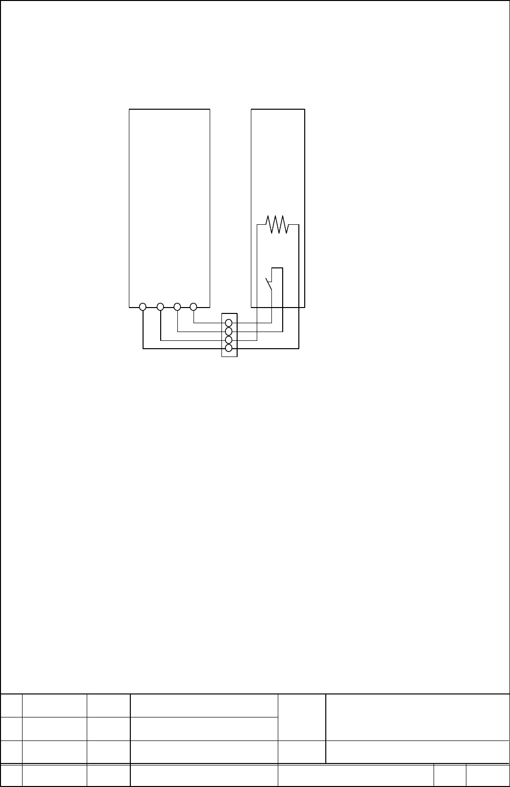
5.5. ConnectionConnection
The following figure shows the connection to the regeneration resistor.
For the details of the other connection, refer to the descriptions of Power Failure Backup
Module (B-65162E/03-08).
TB3
Power Failure
Backup Module
Regeneration
resistor
RE1 RE2 TH1 TH2
Resistor
Thermostat
Connection
terminal
6. 6. OthersOthers
(1) Set up the regeneration resistor in the place where the hand does not touch directly.
After the power failure backup operates, the surface becomes a high temperature.
(2) Set up the regeneration resistor so that the oil mist etc. should not adhere.
In case that the oil mist etc. adheres to the regeneration resistor, there is a possibility
that the oil mist etc. infiltrates and deteriorates the insulation though the
regeneration resistor is filled up with the cement.
(3) There is a possibility that the internal element wire of the regeneration resistor is
blown out in case that the regeneration is operated continuously.
The regeneration resistor is specified to operate from the state of ambient
temperature.
(4) In case that the wire length of the regeneration resistor is short, use the connection
terminal as shown above.
(5) Drawing No. of Power Failure Backup Module: A06B-6077-H001 and A06B-6077-H002
Contents Summary of Regeneration discharge resistor for Stop Distance Reduction function in Power Failure Additional Manual
- Page 1Regeneration discharge resistor for Stop Distance Reduction Function in Power Failure 1. Summary This document describes Regeneration discharge resistor for Stop Distance Reduction Function in Power Failure (Machine Protection Function in Power Failure). 2. Ordering Number Name Drawing Number Regene
- Page 24. Outline dimension Resistor Thermostat 2 2 (2mm ) (0.2mm ) 300 300 2-Ø4.5 250 234 2-4.5 2.5 60 40 80 Regeneration discharge resistor Subject for Stop Distance Reduction Function in Power Failure 01 03.Aug.’01 S.Hanyu Newly designed DWG.N A-53866E-401 o. Ed. Date Name Detail of modification FANUC L
- Page 35. Connection The following figure shows the connection to the regeneration resistor. For the details of the other connection, refer to the descriptions of Power Failure Backup Module (B-65162E/03-08). Power Failure Regeneration Backup Module resistor Resistor Thermostat TB3 RE1 RE2 TH1 TH2 Connecti