FANUC Series 30i/300i/300is/31i/310i/310is/32i/320i/320is-MODEL A Additional Manual Page 3
Additional Manual
EDIT.
FANUC LTD
SHEET
DRAW. NO.
CUST.
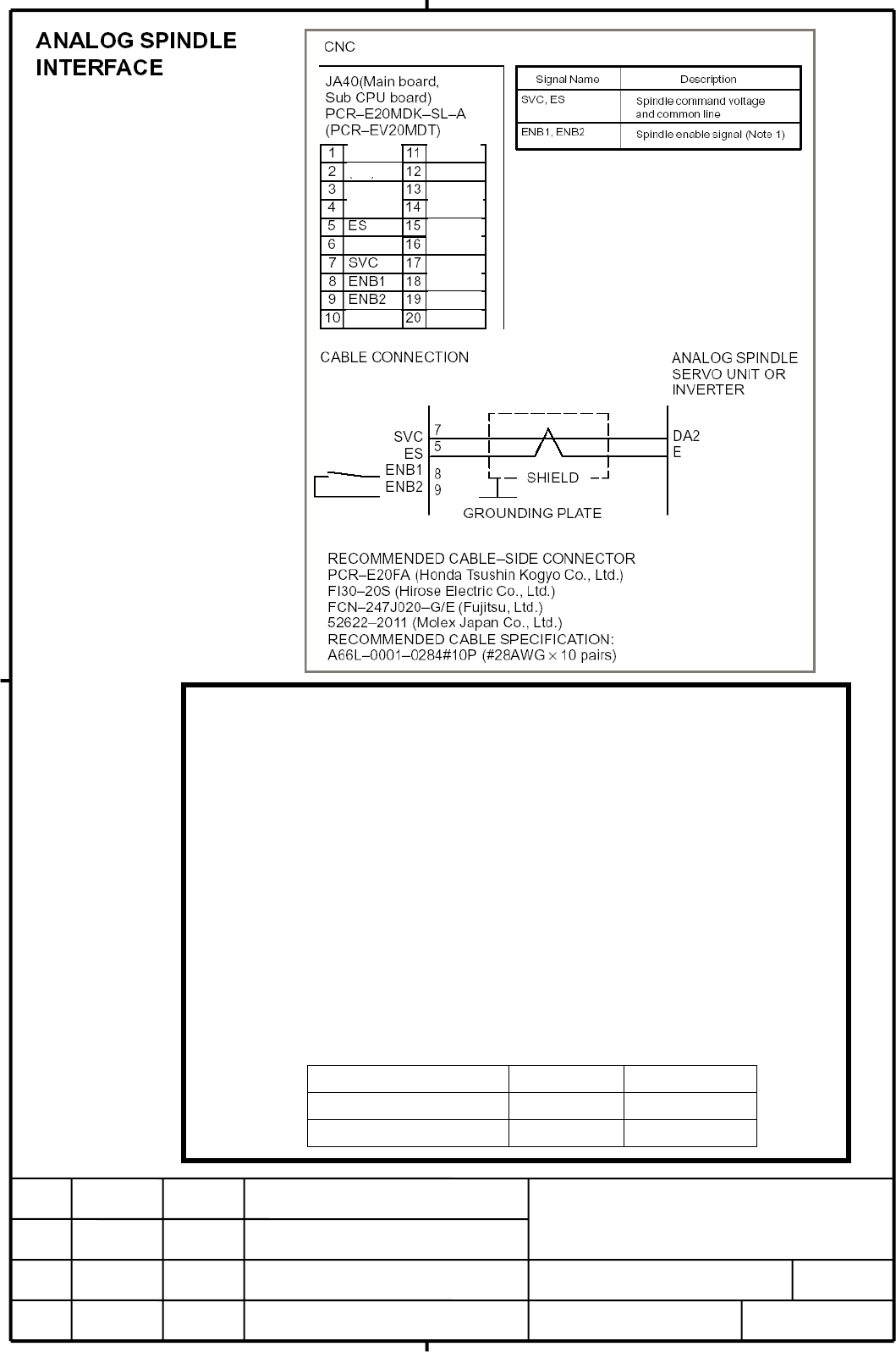
TITLE
DESCRIPTIONDESIG.DATE
FANUC Series 30i/300i/300is/31i/310i/310is/
32i/320i/320is-MODEL A
A
nalog spindle connection material
A
-65557EN/01
3/5
NOTE
1. When signals ENB1 and 2 turn off, the spindle command voltage is not valid including
CNC’s power ON/OFF moment. Use these signals at an applied voltage of 30 or less
when signals ENB1 and 2 are OFF and at a current of 200mA or less when ON.
2. The analog output ratings are as follows;
Output voltage:±10V
Output current :2mA(MAX)
Output impedance:100Ω
3. The parenthesized are used for the high-speed skip function(HDI).
4. The upper connector specification of JA40 is used with the LCD-mounted type CNC. The
lower connector specification (in parentheses) is used with the stand-alone type CNC.
5. The recommended cable connector FI30-20S(manufactured by HIROSE Electric) cannot
be used for the stand-alone type CNC in following combination.
Specification Manufacturer
Connector case FI-20-CV7 HIROSE Electric
Connector case+connector FI30-20S-CV7 HIROSE Electric
0V
0V
0V
0V
0V
0V
0V
0V
( )
( )
( )
( )
( )
( )
( )
( )
02 05.06.24 Komaki Note column is modified.
Contents Summary of FANUC Series 30i/300i/300is/31i/310i/310is/32i/320i/320is-MODEL A Additional Manual
- Page 1The connection of analog spindle When analog spindle is used, the servo card D11,D12 or D24 is required. These servo cards have analog spindle function. The connectors for analog spindle function are on the CNC main board. Connection diagram MAIN BOARD Analog spindle output A-OUT & HDI(JA40) High-sp
- Page 2
Control method and Connector Remarks maximum number of name axes HRV2 HRV3 HRV4 First FSSB line 16axes 10axes 4 axes COP10A-1 On the servo card Second FSSB line 0 axes 2 axes 0 axes COP10A-2 On the servo card Third FSSB line 8 axes 10 xes 4 axes COP10A-3 On the additional axis board - Page 3( ) ( ) 0V 0V ( ) ( ) 0V 0V ( ) ( ) 0V ( ) 0V ( ) 0V 0V NOTE 1. When signals ENB1 and 2 turn off, the spindle command voltage is not valid including CNC’s power ON/OFF moment. Use these signals at an applied voltage of 30 or less when signals ENB1 and 2 are OFF and at a current of 200mA or less when
- Page 4NOTE 1 Signals SIN, *SIN, SOUT and *SOUT are for a serial spindle. These signals are not used for an analog spindle. 2 As the connector on the cable side, the solder-type 15 pin connector(FI40B-2015S, or conventional FI40-2015S) manufactured by Hirose Electric cannot be used. 3 The upper connector s
- Page 5The position coder generates rectangular wave voltage signals in proportion to the angle of rotation of the spindle, and is used in feed per revolution and thread cutting. (1) 1 rotation of position coder with respect to 1 rotation of spindle (2) 1 rotation of position coder with respect to 2 rotati