Connection of the External Battery Case for CNC Additional Manual Page 2
Additional Manual
Edit.
DATE Design
Description
DRAW. NO.
A-73123EN-094
CUST.
01 04/09/24
New issed
Sone
TITLE
Connection of the external battery case for
CNC
SHEET
1 / 1
Abstract
We describe a connection, cable connecting, of the external battery case without the connecting cable for
CNC in FS16i/160i/160is/18i/180i/180is/21i/210i/210is -MODEL A/B.
1. Order specification
Specification of Battery case: A02B-0236-C282
A difference between this external battery case and the current one, A02B-0236-C281, is whether or not
the case has the connecting cable with CNC.
Dimensions and installation of this battery case is the same as the current one.
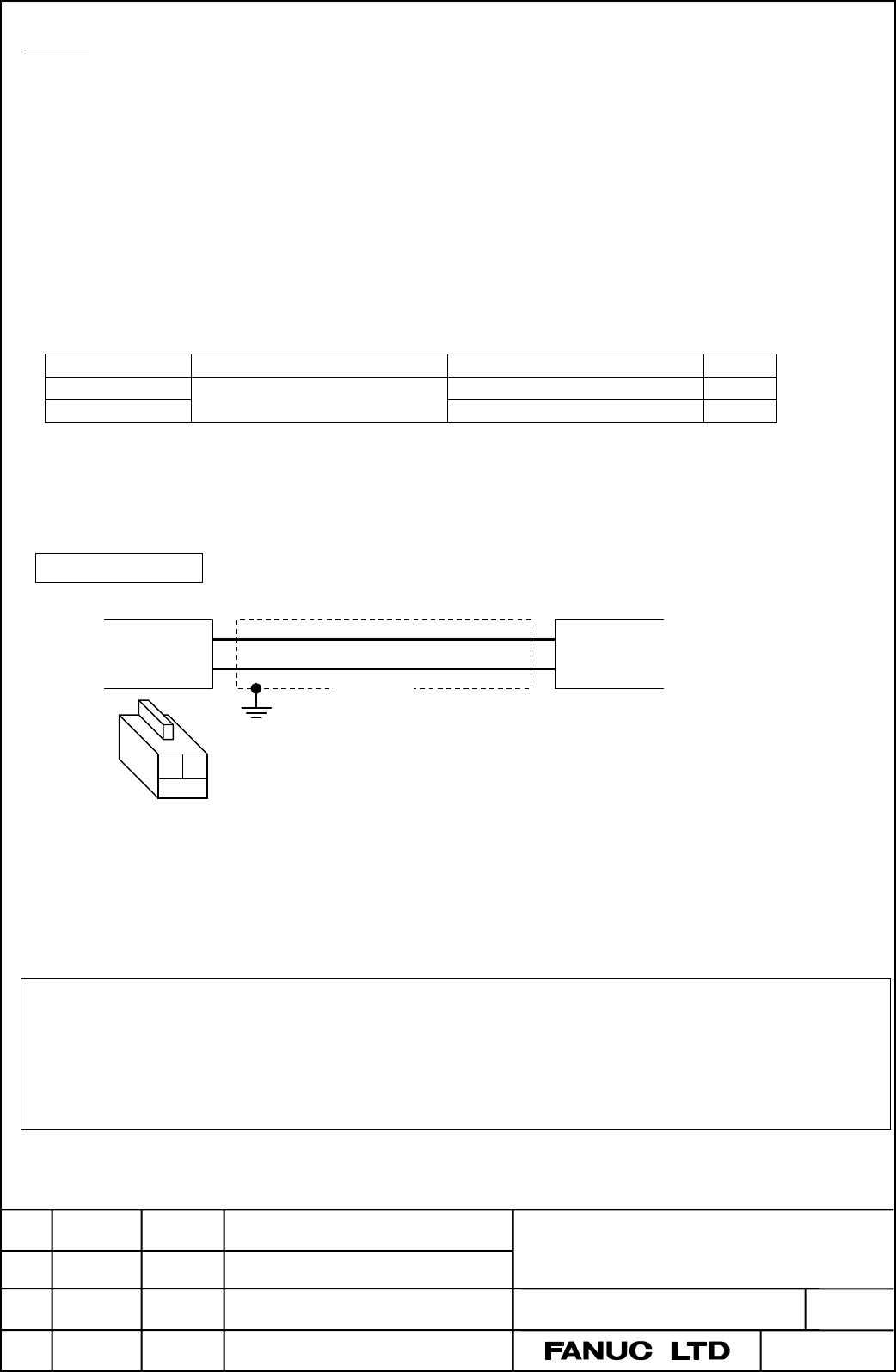
2. Cable connection
Please use the following connector in CNC control unit side.
Product name Manufacturer Manufacturer’s model code Q’ty
Housing IL-2S-S3L-B(N) 1
Contact
Japan Aviation Electronics
Industry, Ltd.
IL-C2-1-00001 2
A special crimping tool is necessary to attach contact to a cable.
It should be ordered from a manufacturer, Japan Aviation Electronics Industry, Ltd., separately.
As the cable is screwed down by M4 screw in the battery case, please use crimp terminal 1.25-4, etc.
Cable connecting
CNC control unit side Battery case side
(Pin assignment of connector housing)
Recommended wire specification:
0.3mm
2
or more (A4-PBCS2W-12/0.18 made by OKI Electric Cable Co., Ltd., etc.)
Maximum cable length:
14m or less (If the wire is satisfied the above condition.)
Note.
1. Install the battery case in a location where the batteries can be replaced even when the CNC control
unit power is ON.
2. The battery cable connector is attached to the CNC control unit by means of a simple lock system. To
prevent the connector from being disconnected due to the weight of the cable or tension within the cable,
fix the cable section within 50 cm of the connector.
Concluded.
0V (1)
+3V (2)
Shield
0V (−)
+3V (+)
1 2
Contents Summary of Connection of the External Battery Case for CNC Additional Manual
- Page 1TECHNICAL REPORT (MANUAL) NO.TMN 04 /090E Date 24 Sep., 2004 General Manager of CNC Laboratory Connection of the external battery case for CNC 1. Communicate this report to : Your information GE Fanuc-N, GE Fanuc-E FANUC Robotics CINCINNATI MILACRON Machine tool builder Sales agency End user 2. Summ
- Page 2Abstract We describe a connection, cable connecting, of the external battery case without the connecting cable for CNC in FS16i/160i/160is/18i/180i/180is/21i/210i/210is -MODEL A/B. 1. Order specification Specification of Battery case: A02B-0236-C282 A difference between this external battery case an