FANUC Series 16i/18i/21i-TB/MB, 18i-MB5 Safety Function at opening protection door (Safe Spindle Stop function) Other Page 7
Other
A-53867-1817 rev02(7/9)
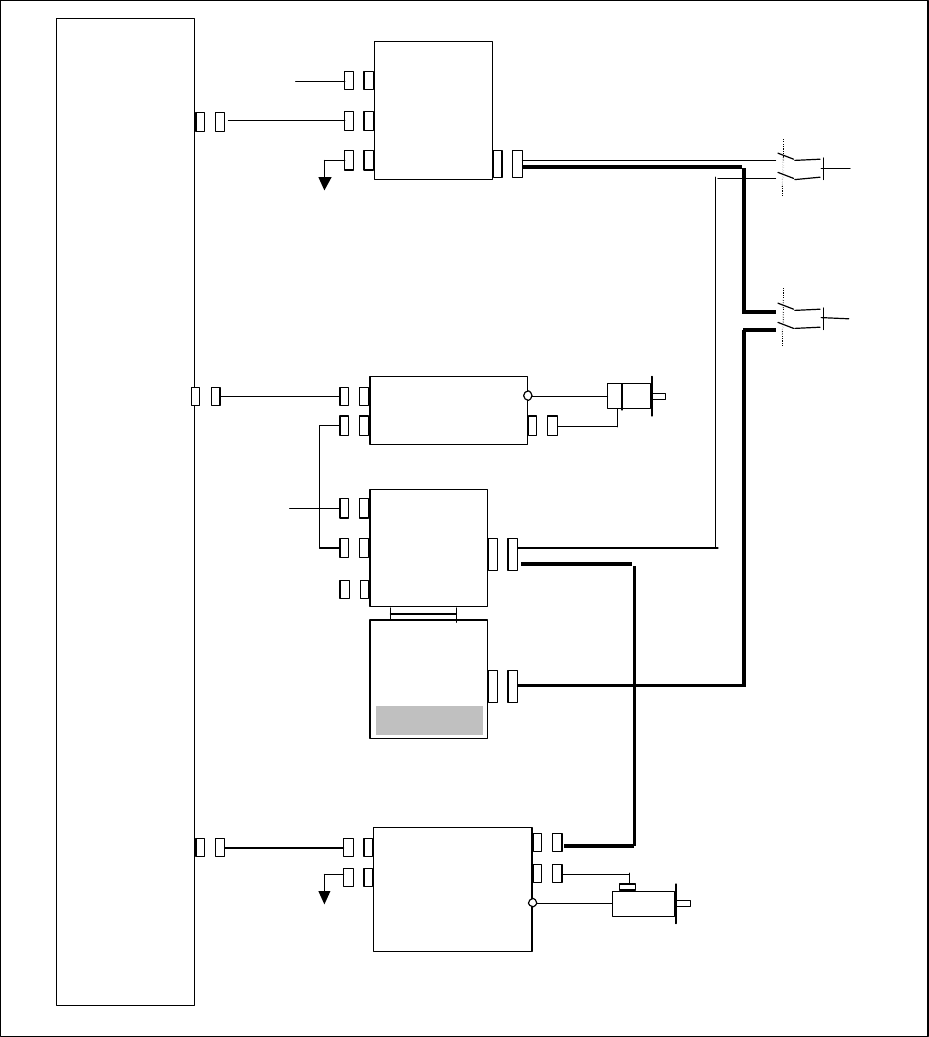
4. Connection
Additional to the standard connection of Dual Check Safety, the wiring is required from
SPM connector JX4 to FSSB I/O. When Spindle enabling switch is used, the external
FSSB I/O is necessary so that the wiring is added from switch to I/O unit and FSSB
I/O.
CNC
I/O-LINK(JD1A)
I/O Unit
CPD1
JD1
JD1
DC24V
FSSB(COP10A
COP10B
COP10A
TB2
JF1
SVM
COP10B
COP10A
FSSB I/O
CP11A
DC24V
SPDL(JA41)
JA7B
JA7A
JY
A2
TB2
To 2
nd
Spindle
SPM
Safe Guard
Status signal
SGD
Spindle
Enabling
Switch SPEN
JX4
Spindle
exitation
off state
EXOF2
C
NF2
C
NF1
Extended
Contents Summary of FANUC Series 16i/18i/21i-TB/MB, 18i-MB5 Safety Function at opening protection door (Safe Spindle Stop function) Other
- Page 1FANUC Series 16i/18i/21i-TB/MB FANUC Series 18i-MB5 Safety Function at opening protection door (Safe Spindle Stop function) 1. Outline This function achieves safe power off of the spindle axis by the double monitoring function combining with FANUC Dual Check Safety. On the present Dual Check Safety,
- Page 22. System configuration In addition to alpha i series Spindle Amplifier Module corresponding to the function which outputs the motor power off (EXOF) signal, the following system is required in order to correspond to this function. l Spindle Amplifier module which applied : A06B-61xy-Huvw#H5ab#C xy=
- Page 33. Safe functions Only the contents added to standard Dual Check Safety is written in this document. As for the standard Dual Check Safety contents, refer to the B-63494. 3.1 Scope [ Safe monitoring function of spindle excitation] It supervises that the drive of a motor is turned off, without discon
- Page 43.2 Surveillance of spindle Excitation OFF signal In order to perform surveillance for two Excitation OFF signals outputted from Spindle Amplifier Module (EXOF, EXOF2 by contact driver), connect Safe I/O both of them for the test of signal and make a PMC ladder to operate excitation on/off of the sp
- Page 5a. Detail of PMC User ladder l Release guard lock(*LGDM) under the condition of open guard request(ORQ) and stopping of spindle by checking spindle excitation signal (EXOF=1). l When turning on power, since EXOFA is not valid until transmission between CNC and Spindle Amplifier connected, mask EXOF
- Page 6(3) Sequence of FSSB I/O Rotation of Spindle Opening of guard Closing of guard Spindle drive enable EXOF2 abnormal SGD2 SPEN2 (*1)Mask the alarm by timer 1st channel alarm Surveillance *1 Although PMC alarm conditions are detected until a spindle stops excitation (EXOF2 becomes 1) after spindle-axis
- Page 74. Connection Additional to the standard connection of Dual Check Safety, the wiring is required from SPM connector JX4 to FSSB I/O. When Spindle enabling switch is used, the external FSSB I/O is necessary so that the wiring is added from switch to I/O unit and FSSB I/O. CNC I/O Unit DC24V CPD1 Safe
- Page 84.1 Wiring from SPM JX4 to FSSB I/O SPM JX4 FSSB I/O with R415 CB155A (11) COMEXOF 24V A01,B01 (13) EXOF2 DI Axx Isolated Opt-coupler 0V Half-pitch connector Hirose electric. Connector and case FI40B-20S-CVS5 Contact specification of SPM Circuit method: Opto-coupler having electrical direction Rated
- Page 95. Input/Output signal Refer to following document to use Safety Programmable Safe-related I/O signals. FANUC Series 16i/18i/21i–TB/MB FANUC Series 18i-MB5 Dual Check Safety Programmable Safe-related I/O signals Specifications A-78882 6. Parameter In addition to the standard parameter of Dual Check