Cylindrical interpolation cutting point control Additional Manual Page 14
Additional Manual
Title
No.
FANUC Series 16i/18i –MA/MB
Cylindrical interpolation cutting point control
A-78436E
Page
13/20
Newly registered
Ver Date Design Description
01 01.03.16 Hosokawa
- Reference axis setting (parameter No. 1031)
If the increment system of a linear axis differs from that of a rotation
axis in cylindrical interpolation, set, as the reference axis, the axis
number of the linear axis for cylindrical interpolation.
Example
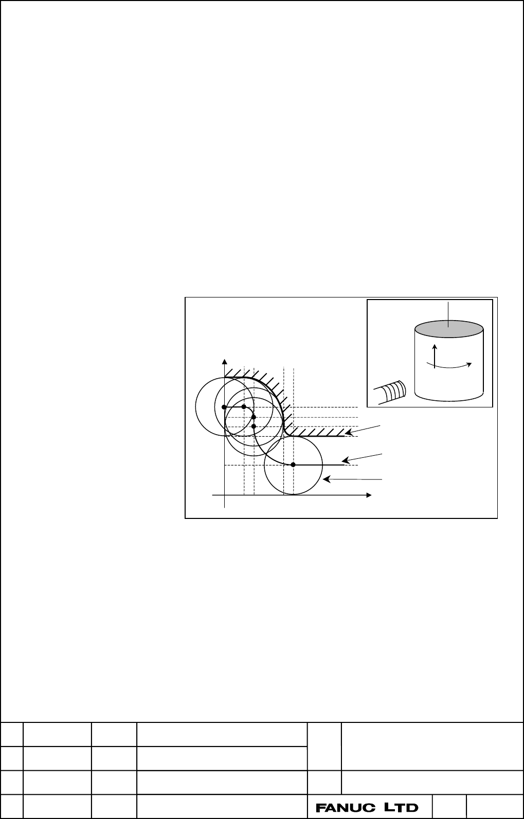
- Example of cylindrical interpolation cutting point compensation
The sample program below indicates the positional relationships
between a workpiece and tool.
O0001(CYLINDRICAL INTERPOLATION1) ;
N01 G00 G90 Z100.0 C0 ;
N02 G01 G91 G19 Z0 C0 ;
N03 G07.1 C57299 ;
N04 G01 G42 G90 Z120.0 D01 F250. ; - - - (1)
N05 C20.0 ; - - - (2)
N06 G02 Z110.0 C60.0 R10.0 ; - - - (3)
N07 G01 Z100.0 ; - - - (4)
N08 G03 Z60.0 C70.0 R40.0 ; - - - (5)
:
M30 ;
Fig.1 (j) Path of Sample Program for Cylindrical Interpolation Cutting
Point Compensation
Z-axis
C-axis on the Cylindrical surface
Tool center path
Programmed path
Tool
20 30
60 70 (deg)
30
60
70
80
90
120
(mm)
C-axis on the
Cylindrical
surface
Z-axis
Tool
(1)
(2) (3)
(4)
(5)
Contents Summary of Cylindrical interpolation cutting point control Additional Manual
- Page 1TECHNICAL REPORT (MANUAL) No.TMN 01/047 Date : Mar. 29, 2001 General Manager of Software Laboratory FANUC Series 16i/18i-MA/MB Cylindrical Interpolation Cutting Point Control 1. Communicate this report to: Your information only ○ GE Fanuc-N, GE Fanuc-E FANUC Robotics MILACRON ○ Machine tool builder
- Page 2FANUC Series 16i/18i –MA/MB Cylindrical interpolation cutting point control This specification may be modified for improvement without notice. FANUC Series 16i/18i –MA/MB Title Cylindrical interpolation cutting point control 01 01.03.16 Hosokawa Newly registered No. A-78436E Ver Date Design Descript
- Page 3Contents CYLINDRICAL INTERPOLATION CUTTING POINT CONTROL.................................................... 3 General .................................................................................................................................................... 3 Format .......................
- Page 41. CYLINDRICAL INTERPOLATION CUTTING POINT CONTROL General The conventional cylindrical interpolation function controls the tool center so that the tool axis always moves along a specified path on the cylindrical surface, towards the rotation axis (cylindrical axis) of the workpiece. On the other ha
- Page 5Format G05 P10000 ; Sets AI High precision contour control mode. : G07.1 IPr ; Sets cylindrical interpolation mode. : ..G41(G42).. Sets cutter compensation mode. : ..G40.. Clear cutter compensation mode. : G07.1 IP0 ; Clears cylindrical interpolation mode. G05 P0 ; Clears AI high precison contour co
- Page 6Z-axis V :C-axis component of C1 - C2 C1 :Cutting surface of block N1 C2 :Cutting surface of block N2 S1 C2 Cutting surface of block N2 N1 C1 Programmed path V N2 C-axis on the cylindrical surface Y-axis Fig.1 (b) Cutting Point Compensation between Blocks FANUC Series 16i/18i –MA/MB Title Cylindrica
- Page 7(2) Cutting point compensation in a circular command block As shown in Fig.1 (c), the movement required for cutting point compensation is made simultaneously with circular interpolation in block N1. 1) Let C0 be the head of the vector normal to N1 from S0, which is the tool center position at the st
- Page 8(3) When cutting point compensation is not applied between blocks When, as shown in Fig.1 (d) andFig.1 (e), the cutting point compensation value (V in the figures) is less than the value set in parameter No. 6112, one of the operations below is performed. (The operation that is performed depends on
- Page 92) When bit 6 (CYS) of parameter No. 6004 is set to 0 Cutting point compensation is not performed between blocks N1 and N2. Whether to apply cutting point compensation between block N2 and N3 is determined by taking the cutting point compensation value between blocks N2 and N3 (V1 in the figure) int
- Page 103) When the amount of travel (L1) of block N2 is less than the value set in parameter No. 6113, as shown in Fig.1 (f), cutting point compensation is not applied between blocks N1 and N2. Instead, block N2 is executed with the cutting point compensation of the previous block. When the amount of trave
- Page 114) When, as shown in Fig.1 (g), the diameter of an arc (R in the figure) is less than the value set in parameter No. 6113, cutting point compensation is not applied simultaneously with circular interpolation V :Cutting point compensation between blocks N2 and N3 C1 :Cutting surface of blocks N1 and
- Page 12- Feedrate during cutting point compensation (1) The tool moves at a specified feedrate while cutting point compensation is being applied between blocks. (2) The actual speed indication and feedrate during circular interpolation are as described below. Actual speed indication The speed component of
- Page 13- Usable G codes (1) In any of the following G code modes, cylindrical interpolation cutting point compensation can be specified: G17,G18,G19: Plane selection G22 : Stored stroke check function on G64 : Cutting mode G90,G91 : Absolute command programming, incremental command programming G94 : Feed p
- Page 14- Reference axis setting (parameter No. 1031) If the increment system of a linear axis differs from that of a rotation axis in cylindrical interpolation, set, as the reference axis, the axis number of the linear axis for cylindrical interpolation. Example - Example of cylindrical interpolation cutti
- Page 15Positional relationship between the Positional relationship between the workpiece and tool of (1) workpiece and tool of (2) Rotation Workpiece Rotation 0° 0° 20° Cutting surface Tool Y-axis Y-axis Tool center Positional relationship between the Positional relationship between the workpiece and tool
- Page 16- Example of specifying cylindrical interpolation cutting point compensation and normal direction control at the same time Cutter compensation value No. 01 = 30 mm O0002(CYLINDRICAL INTERPOLATION2) ; N01 G00 G90 X100.0 A0 ; N02 G01 G91 G17 X0 A0 ; N03 G07.1 C57299 ; N04 G01 G41 G42.1 G90 X120.0 D01
- Page 17Parameter #7 #6 #5 #4 #3 #2 #1 #0 1006 ROT [In pu t t ype] P a r a m et er in pu t [Da t a t ype] Bit a xis #0 ROT Specifies whether the axis requires inch/metric conversion. 0: Axis requires inch/metric conversion (linear axis). 1: Axis does not require inch/metric conversion (rotation axis). Set t
- Page 181022 Designation of each axis in relation to the basic coordinate system [In pu t t ype] P a r a m et er in pu t [Da t a t ype] Wor d a xis [Va lid da t a r a n ge] 0-7 Planes selected for circular interpolation, cutter compensation, and so forth G17: Xp-Yp plane G18: Zp-Xp plane G19: Yp-Zp plane Se
- Page 19#7 #6 #5 #4 #3 #2 #1 #0 19530 CYS CYA [In pu t t ype] P a r a m et er in pu t [Da t a t ype] Bit #5 CYA Specifies wh et h er t o per for m cylin dr ica l in t er pola t ion cu t t in g poin t com pen sa t ion du r in g AI/AI NANO h igh pr ecision con t ou r con t r ol m ode. 0: P er for m . 1: Do n
- Page 2019534 Limit for changing cylindrical interpolation cutting point compensation in a single block [In pu t t ype] P a r a m et er in pu t [Da t a t ype] Rea l [Un it of da t a ] m m , in ch (in pu t u n it ) [Min im u m u n it of da t a ] Depen d on t h e in cr em en t syst em of t h e r efer en ce a
- Page 21Alarm and message Number Message Contents P/S0015 TOO MANY AXES COMMANDED A move command was specified for more axes than can be controlled by simultaneous axis control. Either add on the simultaneous axis control extension option, or divide the number of programmed move axes into two blocks. P/S017