FANUC Series16i/160i-LB, Gap Control Axis High-Speed Approach Function, Specification Additional Manual Page 6
Additional Manual
Edit
Reco
g
nition
6/10
Desi
g
n
FANUC Series 16i/160i -LB
Gap control axis high-speed approach function
A – 78797E
02.05.06
Contents
Date
Design
M.Sato
Title
Drawing
Page
04 2004.07.29 M.Sato NPDS signal has been added.
03 2004.05.20 M.Sato All pages has been changed.
02 2002.09.03 M.Sato Page 7 Error in writing correction
Signals
- Deceleration starting signal
*APDEC<HDI1>
[Classification] Input signal (High-speed DI interface)
[Function] This signal makes the approach speed shift from the parameter value to the
value calculated by gap control.
The high-speed approach operation is ended and the gap control axis starts decelerating.
[Operation] Deceleration starting signal can command to decelerate the gap control axis from the
approach speed when PRM No.15840#2(GDS) is 1.
The signal should be kept 1 at normal status and switched to 0 at deceleration start point.
Switching the signal to 0 makes ending the high-speed approach operation and starting the
deceleration of the axis while switching the deceleration request receive signal (APDON) to
1.
The deceleration starting signal uses HDI1 of high-speed DI interface.
High-speed DI signals except for HDI1 can be used by other functions.
Please refer to FANUC Series 16i-MODEL B connecting manual (hardware) (B-63523) for
details of the high-speed DI interface.
- Pierce point signal
LPP<HDI2>
[Classification] Input signal (High-speed DI interface)
[Function] This signal stops the gap control axis and starts the next block.
[Operation] This signal can stop the approaching of gap control axis when PRM No.15840#4(LPP) is 1.
Switching the signal to 1 during approaching of gap control axis makes quick stop of the gap
control axis and starting the next block.
The pierce point signal uses HDI2 of high-speed DI interface.
High-speed DI signals except for HDI2 can be used by other functions.
Please refer to FANUC Series 16i-MODEL B connecting manual (hardware) (B-63523) for
details of the high-speed DI interface.
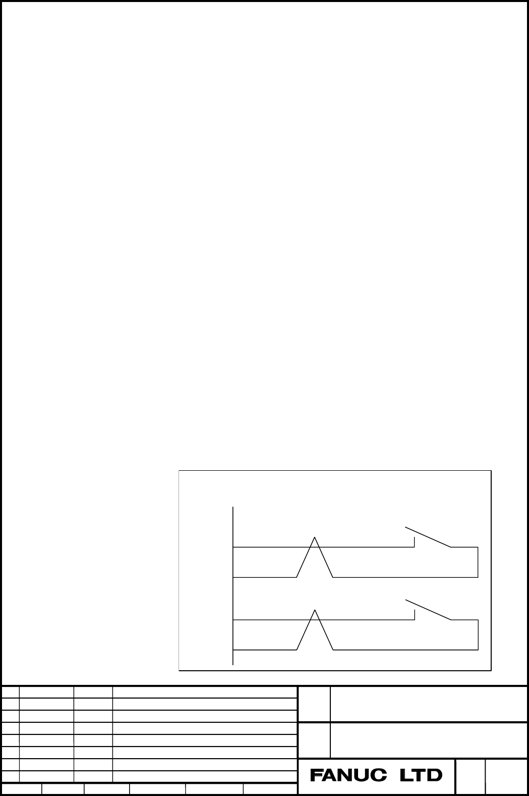
11
12
HDI1
0V
*APDEC
Cable connections
JA40 (FS16
i
-LA/LB)
3
4
HDI2
0V
LPP
Contents Summary of FANUC Series16i/160i-LB, Gap Control Axis High-Speed Approach Function, Specification Additional Manual
- Page 1FANUC Series16i/160i-LB Gap control axis high-speed approach function Specification Copyright 2004 FANUC LTD. FANUC Series 16i/160i -LB Title Gap control axis high-speed approach function 04 2004.07.29 M.Sato NPDS signal has been added. Drawing A – 78797E 03 2004.05.20 M.Sato All pages has been ch
- Page 2Outline The approach speed of the gap control function is controlled according to the value multiplied the gap control gain and the gap deflection. The larger the gap control gain is set, the faster the approach speed is and the shorter the approach time is. However, raising the gap control gain too
- Page 3- High-speed approach operation The approach operation when the gap control axis high-speed approach function is effective is as follows. (1) When the gap control is started, the gap control axis starts the approach operation at the approach speed (PRM No.15845). Please set the acceleration time con
- Page 4Operation at Pierce point The gap control axis can be stopped at an arbitrary position to pierce a hole while approaching. The procedure is explained with using the following example part program. (1) Specify PRM No.15840#4(LPP) for 1 and specify Pierce point stop signal (NPDS) for 1, and this opera
- Page 5The gap control axis immediately stops without deceleration when the pierce point signal is set to 1. So, setting the piercing point signal to 1 with the axis moving at high speed might cause shock in the machine. Please slow down the gap control axis by using the deceleration beginning signal (* AP
- Page 6Signals - Deceleration starting signal *APDEC
[Classification] Input signal (High-speed DI interface) [Function] This signal makes the approach speed shift from the parameter value to the value calculated by gap control. The high-speed approach operation is ended and the gap control axis start - Page 7- Deceleration request receive signal NPDS
- Page 8Parameter #7 #6 #5 #4 #3 #2 #1 #0 15840 LPP GDS TRB [Data type] Bit TRB Specify whether Gap control B function are enabled or disabled. 0: Disabled 1: Enabled GDS Specify the method of commanding the deceleration start of the gap control axis in the gap control axis high-speed approach function. 0:
- Page 915847 Deceleration time constant [Data type] Word axis [Unit of data] msec [Valid data range] 0 to 32767 Specify the time from the approach speed to the stop.. Setting too large value to this parameter might cause touching the gap control axis to work-piece. Please be careful in case of changing thi
- Page 1015855 Acceleration limit at approaching [Data type] Word axis [Unit of data] 0.1m/min2 [Valid data range] 0 to 32767 Specify the limit of acceleration for gap control speed. The servo over-current alarm may occur at gap control start, because the gap control axis starts without time constant of acce