Fanuc Panel I New Options Additional Manual Page 23
Additional Manual
EDIT.
SHEET
DRAW. NO.
CUST.
TITLE
18
/
20
DESCRIPTIONDESIG.DATE
FANUC PANEL i New Options
A-
81226E
400
320
2
30
128
125
(HOLE)
384
304
5
5
5
5
195
155
8-M3
Upper View
Front View Side View
Panel Cutting
Unit [mm]
Weight 8.2kg
(In the case that HDD
unit and PCI extension
board cover are
mounted)
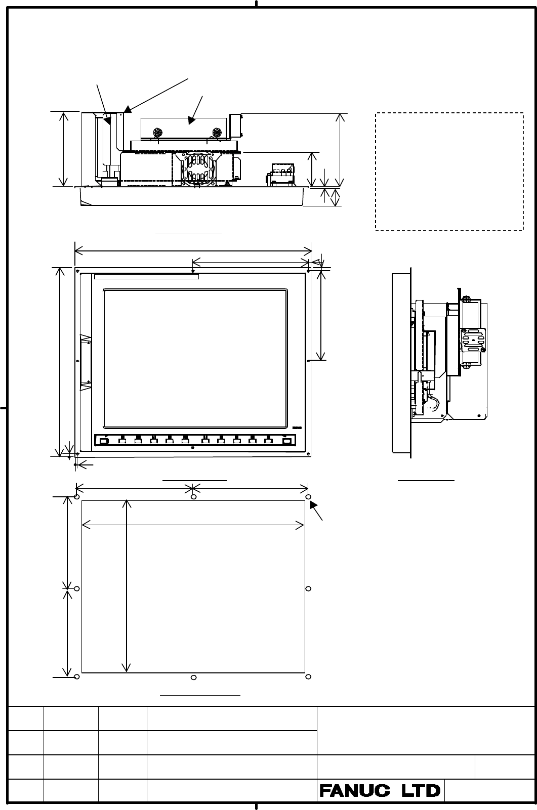
Appendix 3. Outline of 15.0” LCD type Basic Unit in the Case of HDD Unit(Basic
Unit Mounting Type) and PCI Extension Board Cover are mounted.
Note: Depth of Basic Unit is
No options --- 60mm
PCI extension board fitting
plate or HDD unit (Basic
unit mounting type) are
mounted
--- 125mm
PCI extension board cover is
PCI Extension Board Cover
HDD Unit (Basic Unit Mounting Type)
PCI Extension Board Fitting
155
195
195
155
60
Contents Summary of Fanuc Panel I New Options Additional Manual
- Page 1TECHNICAL REPORT (MANUAL) No. TMN02/035E Date. 22. March 2002 General Manager of Hardware Laboratory FANUC PANEL i New Options 1. Communicate this report to: O Your information O GE Fanuc-N, GE Fanuc-E FANUC Robotics CINCINNATI MILACRON O Machine tool builder ( dealt by GE Fanuc only) Sales agency E
- Page 21. Application This report is applied to FANUC PANEL i 2. Outline This report describes necessary information for new options of FANUC PANEL i. 2.1 New Basic Unit NAME Order Remark Specification A08B-0082- 10.4” LCD with Soft Key and Basic Unit B062 without Touch Panel (With CRT Output) A08B-0082- 1
- Page 33. Basic Unit (With CRT Output) 3.1 Summary Current PANEL i has a LCD panel, and screen is displayed on this panel. But this new basic unit has a CRT output interface together with LCD panel. Therefore, it is possible to display the screen on the external CRT unit simultaneously when the same screen
- Page 43.2 Order Specification and Outline Order Specifications of Basic unit (with CRT output) are as follows. Order Corresponding Remarks Specification of Basic Unit No. Basic Unit (With CRT Output) 10.4” LCD with Soft Key and 1 A08B-0082-B062 A08B-0082-B032 without Touch Panel 12.1” LCD with Soft Key an
- Page 53.3 Connector Location CRT output connector CA71 is located as follows. PCI Slot 2 CA71 Posiotion of CRT Output Connector (View from back side) 3.4 Restriction (a) PCI slot (slot 2) above the connector of CA71 can not be used by connecting a cable to CA71. (b) Please order PCI Extension Board Fittin
- Page 63.5 Signal Connections Some CRT unit in the market PANEL i include signal cable as a part of CA71 the unit. Make a converter JAE LY20-20P-DTI-P cable in such case. P A B 1 RED 0V 2 0V VSYNC 3 GREEN 0V 4 0V 0V 5 BLUE HSYNC JAE LY10-DC20 (Housing) 6 0V 0V LY10-C2-3 (Contact) 7 SENSE A02B-0236-K303 8 D
- Page 7Recommended Connection Note1: 75 ohm coaxial cable is used at RED, GREEN, BLUE, VSYNC and HSYNC. Note2: The cable length must be 1.5m or less. If more longer cable is necessary, use video signal booster in the market ( please confirm waves of video signals). TITLE FANUC PANEL i New Options DRAW. NO
- Page 84. HDD Unit (Basic Unit Mounting Type) 4.1 Summary Current HDD unit is designed to be mounted on the back side of MDI or FA Full Keyboard. But this HDD unit is designed to be mounted on the back side of basic unit. In following case this HDD unit is convenient. MDI or FA full keyboard is not ordered
- Page 94.4 Applicable Basic Unit This HDD unit can be applied to the following basic units. Specification of applicable basic Remarks unit A08B-0082-B031 to -B038 10.4”LCD Type A08B-0082-B041 to -B048 12.1”LCD Type A08B-0082-B051 to -B058 15.0”LCD Type A08B-0082-B062 10.4”LCD Type A08B-0082-B072 12.1”LCD T
- Page 105. PCI Extension Board Cover 5.1 Summary PCI Extension Board mounted on PANEL i has no protection. This PCI extension board cover protects mounted board, so mounted board can be protected during mounting PANEL i in a machine and maintenance. Note: PCI extension board fitting plate has to be ordered
- Page 115.4 Applicable Basic Unit This PCI extension board cover can be applied to the following basic units. Specification of applicable basic Remarks unit A08B-0082-B031 to -B038 10.4”LCD Type A08B-0082-B041 to -B048 12.1”LCD Type A08B-0082-B051 to -B058 15.0”LCD Type A08B-0082-B062 10.4”LCD Type A08B-008
- Page 126. Punch panel for PANEL i 6.1 Summary FANUC PANEL i is provided with the interface connectors for PC function for example a serial port or a parallel port. But it is not easy to connect/disconnect cables to these connectors for customer or end user after PANEL i is integrated in the machine tool be
- Page 136.3 Construction Punch panel (stand alone type) and FA Full keyboard with punch panel is as bellow figure. Punch panel (stand alone type) USB x2 FA Full keyboard with Serial port punch panel (15”LCD type) Parallel port USB x2 Keyboard/Mouse Serial port Paralle port 6.4 Environmental Requirement This
- Page 146.6 Connecting a. Connector PANEL i JD46 serial port2 /USB JD9 CD32B CD32A parallel port Mouse Keyboard Punch JD46 CD43B CD44 (Note) In case of FA Full keyboard with punch panel, there is not the connector “CD44”. TITLE FANUC PANEL i New Options DRAW. NO . CUST. A-81226E SHEET EDIT. DATE DESIG. DESC
- Page 15b. Serial port2 + USB i) Signal connections PANEL i side Punch panel JD46 ( PCR-E20MD) HIROSE JD46 ( PCR-E20LMDG) 1 RD 11 SD Connector: FI40B- 1 RD 11 SD 20S 2 0V 12 USB1_0V 2 0V 12 USB1_0V 3 DR 13 ER 3 DR 13 ER 4 0V 14 USB2_0V 4 0V 14 USB2_0V 5 CS 15 RS 5 CS 15 RS 6 USB1+ 16 USB2+ 6 USB1+ 16 USB2+
- Page 16c. Parallel port i) Signal connections PANEL i side Punch panel side JD9 ( PCR-E20MD) CD43B ( Dsub-25pin 1 STD0 11 *STB JAE female) Connector: DB-25P 2 STD1 12 0V Housing: DB-C2-J9-S6 1 *STB 14 *AFD 3 STD2 13 *AFD 2 STD0 15 *ERROR 4 STD3 14 0V 3 STD1 16 *INIT 5 STD4 15 *INIT 4 STD2 17 *SLIN 6 STD5 1
- Page 17d. Keyboard / Mouse (For Stand alone type Punch panel) i) Signal connections PANEL i side CD32A (Mini DIN6pin) Punch panel (Keyboard) 6 5 KBCLK CD44 ( LY20_08P) 4 +5V 3 0V A1 MSDATA B1 KBDATA 2 1 KBDATA A2 +5V B2 0V CD32B (Mini A3 MSCLK B3 KBCLK DIN6pin) A4 B4 (Mouse) 6 5 MSCLK JAE 4 +5V 3 0V Connec
- Page 186.7 Connection to peripheral a. Arrangement Punch panel (stand alone type) USB x 2 Serial port 2 Parallel port Mous Keyboard FA Full keyboard with punch panel (15”LCD type) USB x 2 Serial port 2 Parallel port b. USB port CD41 ( USBラ 2) 1 5 USB device 2 6 1 USB1_5V 5 USB2_5V 3 7 in the 4 8 2 USB1- 6
- Page 19c. Serial port 2 CD42 (D-sub9pin Male) 6 DR 1 CD 7 RS 2 RD 8 CS 3 SD Host computer etc. 9 RI 4 ER 5 SG d. Parallel port CD42 (D-sub9pin Male) 14 *AFD 1 *STROBE 15 *ERROR 2 Data 0 16 *INIT 3 Data 1 17 *SLCT IN 4 Data 2 18 0V 5 Data 3 19 0V 6 Data 4 20 0V 7 Data 5 Parallel port device 21 0V 8 Data 6 P
- Page 20e. Keyboard / Mouse (For Stand alone type Punch panel) CD32A (Mini Keyboard DIN6pin) (Keyboard) 6 5 KBCLK 4 +5V 3 0V 2 1 KBDATA CD32B (Mini DIN6pin) Mouse (Mouse) 6 5 MSCLK 4 +5V 3 0V 2 1 MSDATA Recommended Keyboard A86L-0001-0210 - 101 type(in the market):Only for application development or mainten
- Page 21Appendix 1. Outline of 10.4” LCD type Basic Unit in the Case of HDD Unit(Basic Unit Mounting Type) and PCI Extension Board Cover are mounted. PCI Extension Board Fitting PCI Extension Board Cover HDD Unit (Basic Unit Mounting Type) Note: Depth of Basic Unit is 128 125 No options --- 60mm PCI extensi
- Page 22Appendix 2. Outline of 12.1” LCD type Basic Unit in the Case of HDD Unit(Basic Unit Mounting Type) and PCI Extension Board Cover are mounted. PCI Extension Board Fitting PCI Extension Board Cover HDD Unit (Basic Unit Mounting Type) Note: Depth of Basic Unit is No options --- 60mm 125 128 PCI extensi
- Page 23Appendix 3. Outline of 15.0” LCD type Basic Unit in the Case of HDD Unit(Basic Unit Mounting Type) and PCI Extension Board Cover are mounted. PCI Extension Board Fitting PCI Extension Board Cover HDD Unit (Basic Unit Mounting Type) Note: Depth of Basic Unit is 125 128 No options --- 60mm 60 PCI exte
- Page 24Appendix 4. Outline of Punch panel (stand alone type) 38 Upper View 5 220 210 200 210 204 64 (HOLE) for cable 5 connector 5 5 70 70 2 70 70 4- φ4 4- M 80 Panel Front View Side View Unit [mm] TITLE FANUC PANEL i New Options DRAW. NO . CUST. A-81226E SHEET EDIT. DATE DESIG. DESCRIPTION 19/20
- Page 25Appendix 5. Outline of FA Full keyboard with punch panel (15”LCD type) 20 38 Upper View 5 220 210 200 6- φ4 for cable 5 connector 5 39 5 2 70 70 40 Front View Side View Unit [mm] 210 204 (HOLE) 38 6- M 19 19 39 Panel TITLE FANUC PANEL i New Options DRAW. NO . CUST. A-81226E SHEET EDIT. DATE DESIG. D