Series 30i-MODEL A, Three-dimensional error compensation Additional Manual Page 5
Additional Manual
3 / 13
FANUC Series 30i-MODEL A
Three-dimensional error compensation
A-79351E
Ed. Date Design Description
Date Jan.07.’04 Design. Apprv.
Title
Draw
No.
page
Detail
Calculation of compensation
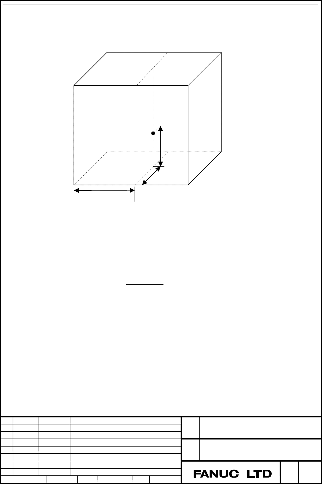
Three-dimensional error compensation is calculated as follows.
Let three compensation axes be X, Y, and Z (three basic axes) and the coordinates of the
current position be P (Px, Py, Pz). consider a compensation space (rectangular parallelepiped)
containing P. Let its vertexes be P1, P2, …, and P8 and the compensation values for the
individual axes at the individual vertexes be Cnx, Cny, and Cnz (where n is a number
between 1 and 8).
Let the interior division ratio on X-axis at P be x. Here, x is standardized in the range of 0 to
1 as follows:
P1x and P2x are the X coordinates of P1 and P2. The interior division ratios on Y and Z-axes
are determined in the same way.
The compensation amount Cx for X-axis at P isdetermined as follows:
The compensation amount Cy and Cz on Y and Z-axes are determined in the same way.
|12|
|1|
xPxP
xPPx
x
−
−
=
zyxxCzyxxC
zyxxCzyxxC
zyxxCzyxxC
zyxxCzyxxCCx
××−×+×××+
×−××+×−×−×+
−××−×+−×××+
−
×−××
+
−
×
−
×
−
×
=
)1(87
)1(6)1()1(5
)1()1(4)1(3
)1()1(2)1()1()1(1
P4 [C4x, C4y, C4z]
P (Px, Py, Pz)
P5 [C5x, C5y, C5z]
P6 [C6x, C6y, C6z]
P1 [C1x, C1y, C1z]
P2 [C2x, C2y, C2z]
P3 [C3x, C3y, C3z]
P8 [C8x, C8y, C8z]
P7 [C7x, C7y, C7z]
x
y
z
Contents Summary of Series 30i-MODEL A, Three-dimensional error compensation Additional Manual
- Page 1TECHNICAL REPORT NO. TMN 04/020E Date :Mar .30, 2004 General Manager of Software Laboratory FANUC Series 30i-A Newly additional functions 1. Communicate this report to: Your information only GE Fanuc-N, GE Fanuc-E FANUC Robotics MILACRON Machine tool builder Sales agency End user 2. Summary for Sale
- Page 2FANUC Series30i –A newly additional functions Drawing number Functions 1 A-79227E External Data Input 2 A-79226E One Touch Macro call 3 A-79196E Temporary absolute coordinate setting 4 A-79354E System alarm 5 A-79349E Touch Panel Control 6 A-79253E Distance coded linear scale interface 7 A-79364E Li
- Page 3FANUC Series 30i-MODEL A Three-Dimensional Error Compensation Specifications FANUC Series 30i-MODEL A Title Three-dimensional error compensation Draw A-79351E No. Ed. Date Design Description page Date Jan.07.’04 Design. Apprv. 1 / 13
- Page 4Outline In ordinary pitch error compensation, compensation is applied to a specified compensation axis (single axis) by using its position information. For example, pitch error compensation is applied to X-axis by using the position information of X-axis. Three-dimensional error compensation is a fu
- Page 5Detail Calculation of compensation Three-dimensional error compensation is calculated as follows. P8 [C8x, C8y, C8z] P7 [C7x, C7y, C7z] P5 [C5x, C5y, C5z] P6 [C6x, C6y, C6z] P (Px, Py, Pz) z P3 [C3x, C3y, C3z] P4 [C4x, C4y, C4z] y P1 [C1x, C1y, C1z] P2 [C2x, C2y, C2z] x Let three compensation axes b
- Page 6The actual compensation amounts are the calculated compensation amounts multiplied by the compensation magnifications (Parameter No.10809 to 10811). Number of compensation points Up to 15625 compensation points (up to 25 points per axis) can be set. The numbers of compensation points on the individu
- Page 7Input/output format Three-dimensional error compensation screen allows output/input (punching/reading) of compensation data. The command format is as follows: N……… A1 P…A2 P…A3 P… ; N….. : Data number (compensation point number + 100000) as represented with six digits A1 : First compensation axis A2
- Page 8Input of compensation data using G10 Compensation data can be changed from a machining program, using the programmable parameter input function. Command format G10 L51 ; N…… P.. R… ; N…… P.. R… ; … G11 ; G10 L51 : Three-dimensional error compensation data input mode G11 : Cancellation of three-dimen
- Page 9Three-dimensional error compensation screen You can execute following operation in three-dimensional error compensation screen. (1) input of compensation data (2) Punching of compensation data (3) Reading of compensation data Select screen Three-dimensional error compensation screen is selected in t
- Page 102. Press the key “+” for several times. Then the soft key named “3D ERR COMP” is shown. 3. Press the soft key “3D ERR COMP”, then three-dimensional error compensation screen is selected. FANUC Series 30i-MODEL A Title Three-dimensional error compensation Draw A-79351E No. Ed. Date Design Description
- Page 11Operation 1.Input of compensation data (1) Place the system in MDI mode. (2) Set 1 for parameter PWE (No.8900#0). (3) Select the compensation point number for which data is to be input, using page keys, cursor keys, or soft key [NO. SRH]. (selected number is shown in yellow.) (1) Select the compensa
- Page 12Parameters 10800 Axis for which three-dimensional error compensation is performed (1st axis) 10801 Axis for which three-dimensional error compensation is performed (2nd axis) 10802 Axis for which three-dimensional error compensation is performed (3rd axis) Note When this parameter is set, the power
- Page 13Three-dimensional error compensation point number at the reference 10808 position (3rd axis) Note When this parameter is set, the power must be turned off before operation is continued. [Input type] Parameter input [Data type] Byte Path [Valid data range] From 1 through the number of the compensatio
- Page 1410814 Three-dimensional error compensation interval (3rd axis) Note When this parameter is set, the power must be turned off before operation is continued. [Input type] Parameter input [Data type] Real Path [Unit of data] mm, inch (machine unit) [Minimum unit of data]Depend on the increment system o
- Page 15Notes Caution The setting of compensatin data using programmable parameter input (G10L51) must be specifiedd in canned cycle cancel mode, as with ordinary programmable parameter input (G10L50). Note 1. The controlled axis on which three-dimensional error compensation is to be applied must be a linea