Connection Manual of SUB PANEL E for Machine Operator Additional Manual Page 12
Additional Manual
FANUC LTD EDIT.
DATE
DESIGN
DESCRIPTION
TITLE
DRAW. NO.
CUST.
PAGE
12 / 12
A
- 86420E
TMN05034E_A-8642
0E_02.DOC
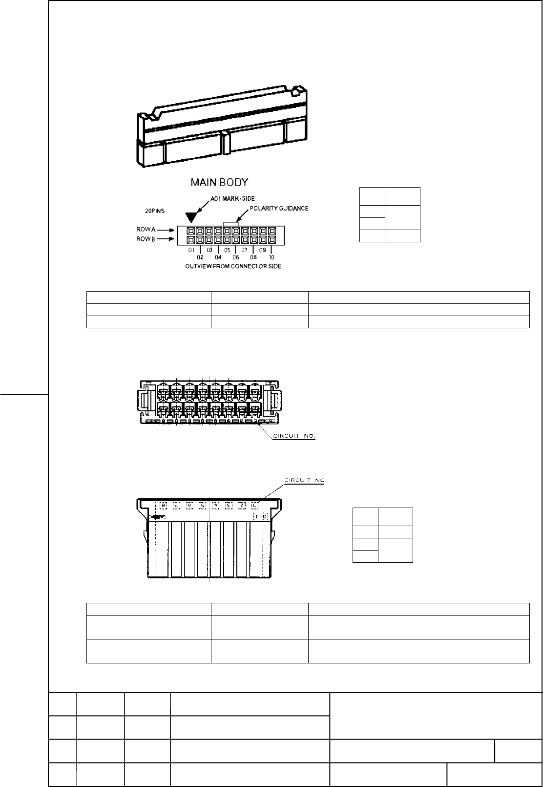
7 Connectors
7.1 Technical Information regarding connectors CM65, CM66 and CA65 of Main Panel B
Name Specification Remarks
Connector CM65, CM66 A02B-0236-K314 For 10 wick flat cable (Cable side connector)
Connector CA65 A02B-0120-K343 For 20 wick flat cable (Cable side connector)
7.2 Technical Information regarding connectors CM67, CM68 and CM69 of Main Panel B
Name Specification Remarks
Connector CM67 A02B-0236-K312 Housing with 10 pieces of contacts
(Cable side connector)
Connector CM68, CM69 A02B-0236-K313 Housing with 20 pieces of contacts
(Cable side connector)
Number
of pins
CM65
CM66
10pin
CA65 20pin
Number
of pins
CM67 10pin
CM68
CM69
20pin
Contents Summary of Connection Manual of SUB PANEL E for Machine Operator Additional Manual
- Page 1Connection Manual of Sub Panel E for Machine Operator’s Panel - Table of contents - 1 Application・・・・・・・・・・・・・・・・・・・・・・・・・・・・・・・・・・・・・・・・・・・・・・・・・・・・・・・・・ 2 2 Designation and Order Specification・・・・・・・・・・・・・・・・・・・・・・・・・・・・・・・・・・・ 2 3 General Information ・・・・・・・・・・・・・・・・・・・・・・・・・・・・・・・・・・・・・・・・・・・・・・
- Page 21 Application This specification describes the technical performance of Machine Operator's Panels. The Machine Operator's Panels are used in combination with PANEL i for Automotive. They are wired out for the connection to Main Panel B and Main Panel B1. 2 Designation and Order Specification A02B-02
- Page 33 General Information 3.1 General All devices are mounted on a base plate made of 2 mm Electric zinc plating steel completely finished and coated. The color is gray; Munsell N3 or RAL in gloss level and color adapted to the FANUC surfaces. The scales of override switches as well as other description
- Page 44 Outline of Sub Panel E 4.1 Outline dimensions 4.2 Mounting depth TITLE CUST. TMN05034E_A-8642 A- 86420E DRAW. NO. 0E_02.DOC PAGE EDIT. DATE DESIGN DESCRIPTION FANUC LTD 4 / 12�
- Page 54.3 Panel cut out dimensions 4.4 Arrangement of switches Axis override Spindle override Memory protect Emergency stop (Rotary switch) (Rotary switch) (Key switch) (Push button switch) TITLE CUST. TMN05034E_A-8642 A- 86420E DRAW. NO. 0E_02.DOC PAGE EDIT. DATE DESIGN DESCRIPTION FANUC LTD 5 / 12�
- Page 64.5 Connection diagram Main Panel B/B1 and Sub Panel E are connected as follows. Main Panel B/B1 Sub Panel E Ribbon cable 10# CM65 Axis override (SA1) A02B-0303-K891 02 Ribbon cable 10# CM66 Spindle override (SA2) A02B-0303-K891 02 Memory protect (SA3) CM67 Emergency stop (SB1) Wiring 4.5.1 Wiring o
- Page 74.5.1.2 Memory protect signal connection Wiring to Main Panel B/B1 and the Memory protect switch (SA3) is contained in Sub Panel E. Sub Panel E Main Panel B/B1 Memory protect P.C.B. switch (SA3) CM67 NO Xm+1.4 A03 0 1 C KEYCOM B03 Note) When Memory protect switch (SA3) is the OFF condition (Editing
- Page 84.5.1.4 Spindle override switch (SA2) Spindle Override Switch (SA2) Significance +24V 1 2 4 8 16 Parity A04 B05 A03 A05 B03 B04 B02 Xm+ Xm+ Xm+ Xm+ Xm+ Xm+ 0.6 0.7 1.0 1.1 1.2 1.3 CM66 The override switch is provided with a cable including connector that fits CM66 socket. Layout of rotary switch SA2
- Page 94.6 Grounding Grounding cable Wire 1.5mm2 or more Connect the earth stud in the Sub Panel E with the ground plate of the cabinet or a nearby plate via the protective grounding terminal. TITLE CUST. TMN05034E_A-8642 A- 86420E DRAW. NO. 0E_02.DOC PAGE EDIT. DATE DESIGN DESCRIPTION FANUC LTD 9 / 12�
- Page 105 Additional Information 5.1 Allocation of Inputs/ Outputs Input/ Connector Contact Description Remarks Output (Main Panel B/B1) (Switch side) 24VDC CM65: A04 Power supply of SA1 SA1: D Xm+0.0 CM65: B05 SA1: A Xm+0.1 CM65: A03 SA1: F Xm+0.2 CM65: A05 SA1: B Axis override Signal input from SA1 Xm+0.3
- Page 116 Sub Panel E specification 6.1 Environmental Requirement Temperature At operation: 0°C ~55°C Around a unit Storing or transporting: -20°C ~60°C Temperature Max. 1.1°C/min variance Humidity Normally: 75% or less (Relative humidity) Short time (Within one month): 95% or less (Relative humidity) Vibra
- Page 127 Connectors 7.1 Technical Information regarding connectors CM65, CM66 and CA65 of Main Panel B Number of pins CM65 10pin CM66 CA65 20pin Name Specification Remarks Connector CM65, CM66 A02B-0236-K314 For 10 wick flat cable (Cable side connector) Connector CA65 A02B-0120-K343 For 20 wick flat cable