Interpolated_straightness_compensation Additional Manual Page 3
Additional Manual
Edit
Apprv
ApprvApprv
Apprv.
..
.Desig
DesigDesig
Desig.
..
.
Sheet
Title
Draw
No.
Date
DateDate
Date
Desi
g
n
Desi
g
nDesi
g
n
Desi
g
n
Descri
p
tion
Descri
p
tionDescri
p
tion
Descri
p
tion
Date
DateDate
Date
FANUC Series 16i/18i-MA
FANUC Series 16i/18i-TA
Interpolated straightness compensation
A-76425EN
2001.03.26
Egashira
3/4
2. Operation
2. Operation2. Operation
2. Operation
2.1 Compensation methods
2.1 Compensation methods2.1 Compensation methods
2.1 Compensation methods
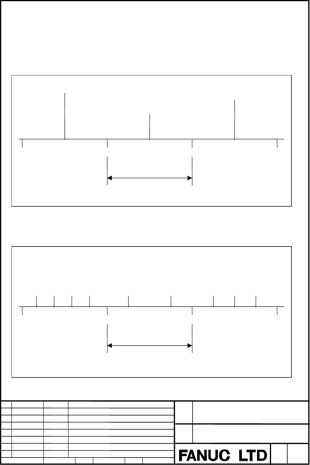
With the 128-point straightness compensation method, the straightness compensation
amount at each compensation point is output to the compensation axis, in the interval
between that point and the next point on the travel axis, as shown in the figure below.
Fig. 2.1(a) 128-Point Straightness Compensation Method
With the interpolated straightness compensation method, the straightness compensation
amount at each compensation point is divided into pulses in the interval between that point
and the next point on the travel axis, and output to the compensation axis.
Fig.2.1(b) Interpolated Straightness Compensation Method
P0: Machine reference position P1 P2 P3
ε1
Pitch error compensation point interval
(ParameterNo.3624)
ε1,ε2,ε3:Straightness compensation amounts
P1,P2,P3 : Pitch error compensation points
ε 2
ε3
Pitch error compensation point interval
(ParameterNo.3624)
ε : Straightness compensation pulse
P1,P2,P3 : Pitch error compensation points
P1 P2 P3
ε
P0: Machine reference position
Contents Summary of Interpolated_straightness_compensation Additional Manual
- Page 1FANUC Series 16i/18i-MA FANUC Series 16i/18i-TA Interpolated straightness compensation Specifications FANUC Series 16i/18i-MA Title FANUC Series 16i/18i-TA Interpolated straightness compensation Draw No. A-76425EN Edit Date Design Description Sheet 1/4 Date 2001.03.26 Desig. Desig. Egashira Apprv. A
- Page 21. Outline Compensation data, which is set using 128-point straightness compensation data, is divided into parts in each compensation point interval and output. FANUC Series 16i/18i-MA Title FANUC Series 16i/18i-TA Interpolated straightness compensation Draw No. A-76425EN Edit Date Design Descriptio
- Page 32. Operation 2.1 Compensation methods With the 128-point straightness compensation method, the straightness compensation amount at each compensation point is output to the compensation axis, in the interval between that point and the next point on the travel axis, as shown in the figure below. ε1 ε3
- Page 42.2 Compensation data Compensation data is set using 128 straightness compensation points. 3. Parameters Parameters #7 #6 #5 #4 #3 #2 #1 #0 3605 IST [Data type] Bit axis IST: Specifies whether to use the interpolating straightness compensation function. 0: Do not use. 1: Use. 4. Alarm and Message No