Terminal module A -Connection Manual Additional Manual Page 8
Additional Manual
EDIT DATE DESIG.
TITLE
DESCRIPTION
DRAW NO
A-80034E
SHEET
CUST
8
/
9
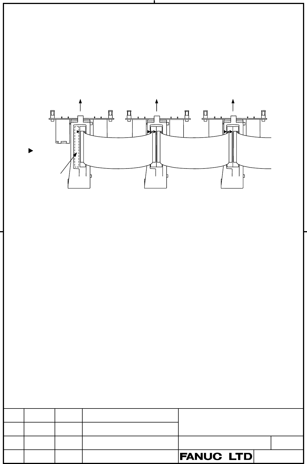
3.3 Connection of Basic and Extension Modules
Connect I/O modules mounted on the Terminal module A by using 34-pin flat cable connectors
as shown in the figure below. Ensure that all 34 pins at one end of the cable are connected to
the corresponding pins at the other end; e.g., connect the A1 pin to the pin having the same
designation (A1) at the other end.
Top view
Flat cable-side connector specification:
HIF3BA-34DA-2.54R (Hirose Electric Co., Ltd.)
Module connector-side specification:
HIF3BA-3403-1202-0BS (Hirose Electric Co., Ltd.) or
FAP-3403-1202-0BS (Yamaichi Denki Co., Ltd.)
Note) Make the length of the flat cable more than 100mm in consideration of wiring to the terminal
blocks on the terminal module A. But, the maximum length of the total extension of the flat
cable is 300mm.
To ensure adequate ventilation, install the modules in such a way that the flat cables lie on
top of them. The basic module has a vent at the top (as indicated by the dotted lines in the
above figure). When connecting modules, install extension modules so that the flat cables
do not cover the vent, as shown in the above figure. Therefore, for direct connection to the
Terminal module A, expansion modules are installed to the right of the basic module on the
installation plane.
Basic module Extension module Extension module
Cabinet side
Cabinet side Cabinet side
A1 pin mark
Ventilation
slot
02 00.01.27
Tsurutani This page is added.
34-pin flat cable
CA52
CA53
CA52
CA52
34-pin flat cable
34-pin
flat cable
CA53
Contents Summary of Terminal module A -Connection Manual Additional Manual
- Page 1Terminal Module A Connection Manual -Item- 1. Overview 2. Total Connection 3. Connection of Each Part 3.1 Terminal and Connector Pin Assignment of the Terminal Module A. 3.2 Connection of DC24V Power Supply and Signals 3.2.1 DC24V Power Supply Connection 3.2.2 DI (Input Signal) Connection 3.2.3 DO (
- Page 21. Overview The Terminal Module A is connected by the Connector Panel I/O Module directly. It is the Terminal Module A that a input/output signal (DI 24 points/DO 16 points) from the machine side can be relayed with the terminal block. And output signal (DO 16 points) are also relayed by a connector
- Page 33. Connection of Each Part 3.1 Pin Assignment Terminal and Connector pin assignment of the Terminal Module XT150A (YOSHIDA PX7-32A) XT150B (YOSHIDA PX7-32A) 17 +24E 17 +24E 1 0V 1 +24E 18 DICOM 18 Xm+2.4 2 DICOM 2 Xm+2.6 19 Xm+0.0 19 Xm+2.5 3 Xm+0.2 3 Xm+2.7 20 Xm+0.1 20 0V 4 Xm+0.3 4 0V 21 DICOM 21
- Page 43.2 Connection of DC24V Power Supply and Signals 3.2.1 DC24V Power Supply Connection DC24V power supply into 2 system of control power supply +24V for the connector panel I/O module and +24E for machine side input/output signal, and it can be supplied. Also one power supply unit can supply to both t
- Page 5Connector Panel I/O Module Terminal Module A +24E Address Number Bit Number XT150A CB150 (30) Xm+2.0 (10) (31) RV Xm+2.1 (11) (32) RV (14) Xm+2.2 (12) (15) RV Xm+2.3 (13) (16) RV XT150B (17) Xm+2.4 (14) (18) RV Xm+2.5 (15) (19) RV (1) Xm+2.6 (16) (2) RV Xm+2.7 (17) (3) RV +24E Note) Xm+0.0 through X
- Page 63.2.3 DO (Output Signal) Connector Connector Panel I/O Module Terminal Module A Address Number +24E X150 Bit Number 0V (A24),(B24),(A25) DOCOM CB150 XT150B (01),(33) (20) (B04) Yn+0.0 (34) (21) Relay DV (B05) Yn+0.1 (35) (22) DV Relay (4) (B03) Yn+0.2 (36) (5) DV (B06) Yn+0.3 (37) (6) DV (23) (A18)
- Page 7“X150”. TITLE DRAW NO CUST A-80034E SHEET EDIT DATE DESIG. DESCRIPTION 7/9
- Page 83.3 Connection of Basic and Extension Modules Connect I/O modules mounted on the Terminal module A by using 34-pin flat cable connectors as shown in the figure below. Ensure that all 34 pins at one end of the cable are connected to the corresponding pins at the other end; e.g., connect the A1 pin to
- Page 94. Mounting the Terminal Module A As for the mounting of the Terminal Module A, a screw or DIN rail mounting is possible. Spacer* M3×6L 15.3 Mounting hole 5 84 5 4-ø4.8 7 6.2 XB1 64 XB2 Dismounting hole 118 144 116 7.62 60 XT150B 37 14 X150 XT150A 51 41 49 45 11.7 106.5 94 (Unit mm) 1.6 Note) When m
- Page 105. Specifications 5.1 Installation Specifications Ambient Temperature At operation 0° to +55°C Storing or transporting -20° to +60°C Temperature Change Max. 1.1°C/min Relative Humidity Normally 75% or less (Relative humidity) Short time (Within one month) 95% or less (Relative humidity) Vibration Op