FS 16i/18i/21i-MB/TB, Expansion of Spindle Functions Additional Manual Page 4
Additional Manual
3. SIGNAL
Spindle contour control change signal for each serial spindle
CONS1~CONS4<G274#0~#3>
[Classification] Input signal
[Function] These signals specify that with the Cs contour control function, the
each serial spindle (the 1st~4th serial spindle) be switched between
the spindle speed control and Cs contour control modes.
When these signals turn to “1”, the spindle mode changes from
speed control to Cs contour control. If the spindle is moving at the
time of the change, it stops immediately.
Turning the signals to “0” change the spindle mode from Cs contour
control back to speed control.
These signals are valid when the parameter CSS (No.3704#7) is “1”.
At this time, signal CON<G027#7> is invalid.
Spindle contour control change completion signal for each serial spindle
FCSS1~FCSS4<F274#0~#3>
[Classification] Output signal
[Function] These signals indicate the axes are under Cs contour control.
Spindle speed control mode : ”0”
Cs contour control mode : ”1”
These signals are valid when the parameter CSS(No.3704#7) is “1”.
At this time, signal FSCSL<F044#1> is invalid.
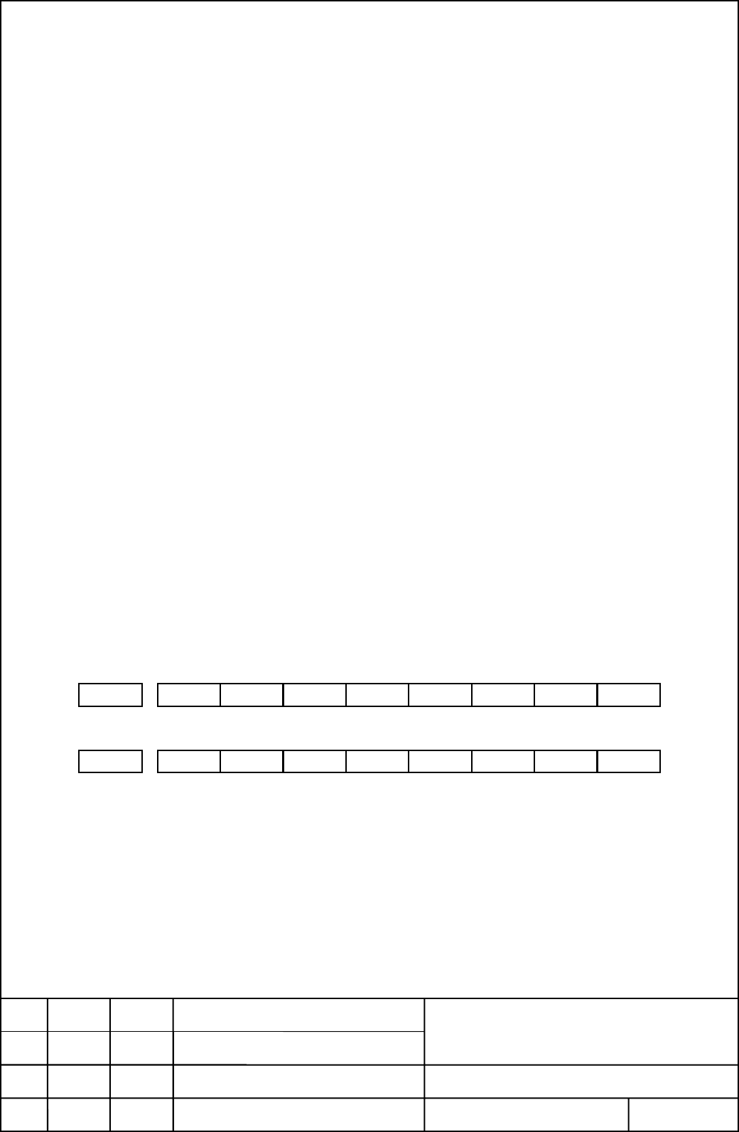
Signal address
#0#1 #2#3#4#6 #5#7
G274 CONS1CONS2 CONS3 CONS4
#0#1 #2#3#4#7 #6 #5
F274 FCSS1FCSS2 FCSS3 FCSS4
The other signals are the same as Cs contour axis when parameter CSS(No.3704#7)
is “0”. Refer to “FS16i/18i/21i CONNECTION MANUAL (FUNCTION) 9.9 Cs
CONTOUR CONTROL”.
EDIT.
DATE DESIG.
DESCRIPTION
TITLE
DRAW.NO
FANUC Series 16i/18i/21i-MB/TB
Cs contour control by each spindle
A-61154E
SHEET
3/06
FANUC LTD
Newly registered M.Ito 97.05.30
01
02 02.10.25
E.Genma
T.Masuda
M.Ito
M.Ito Remove restriction of axis number
Contents Summary of FS 16i/18i/21i-MB/TB, Expansion of Spindle Functions Additional Manual
- Page 1TECHNICAL REPORT NO.TMN 02/093E Date: 08-November-2002 General Manager of Software Development Center FANUC Series 16i/18i/21i-MB/TB Expansion of spindle functions 1. Communicate this report to : ○ Your information ○ GE Fanuc-N, GE Fanuc-E FANUC Robotics CINCINATI MILACRON ○ Machine tool builder Sal
- Page 2FANUC Series 16i/18i/21i-MB FANUC Series 16i/18i/21i-TB Cs contour control by each serial spindle SPECIFICATION - CONTENTS - 1. OUTLINE 2 2. SPECIFICATION 2 3. SIGNAL 3 4. PARAMETER 4 5. ALARM 5 6. NOTE 5 7. REFERENCE ITEM 6 TITLE FANUC Series 16i/18i/21i-MB/TB 02 02.10.25 M.Ito Remove restriction o
- Page 31. OUTLINE This function makes that Cs contour control axes can be controlled with each serial spindle. 2. SPECIFICATION When the parameter CSS (No.3704#7) is “1”, Cs contour control axes can be controlled with each serial spindle. Set the parameter No.1023 that is minus value of the serial spindle
- Page 43. SIGNAL Spindle contour control change signal for each serial spindle CONS1~CONS4
- Page 54. PARAMETER 1023 Number of the servo axis for each axis [Byte type] Byte axis Set the servo axis for each control axis. When Cs contour axes are used, set the parameter No.1023 that is minus value of the serial spindle number. Set value -1 : The 1st serial spindle Cs contour axis -2 : The 2nd seria
- Page 65. ALARM Alarm No. 197 C-AXIS COMMANDED IN SPINDLE MODE The program specified a movement along the Cs contour control axes when the signal CONS1~CONS4
- Page 77. REFERENCE ITEM FS16i/18i/21i CONNECTION MANUAL (FUNCTION) 9.9 Cs CONTOUR CONTROL TITLE FANUC Series 16i/18i/21i-MB/TB 02 02.10.25 M.Ito Remove restriction of axis number E.Genma Cs contour control by each spindle 01 97.05.30 M.Ito Newly registered T.Masuda DRAW.NO A-61154E EDIT. DATE DESIG. DESCR