FANUC Series 30i-A/31i-A5 NURBS Interpolation for 5-Axis Machining Additional Manual Page 3
Additional Manual
3
/
5
Ed.
Apprv.
Person
Date
Person
Contents
Date
2005.03.11
Name No.
FANUC Series 30i-A/31i-A5
NURBS Interpolation for 5-axis Machining
A
-79985E
Page
FANUC LTD.
Overview
Many computer-aided design (CAD) systems used to design metal dies for
automobiles and airplanes utilize non-uniform rational B-spline (NURBS) to
express a sculptured surface or curve for the metal dies. NURBS interpolation
function enables NURBS curve expression to be directly specified to the CNC.
This eliminates the need for approximating the NURBS curve with minute line
segments and offers many advantages such as short part program.
In the conventional NURBS interpolation, up to three axes can be specified as
the axis of NURBS interpolation. On the other hand, in NURBS interpolation for
5-axis machining, up to five axes including two rotary axes can be specified.
According to 5-axis machining with rotary axes, much smoother surface is
realized.
Moreover NURBS interpolation for 5-axis machining can be used during Tool
center point control for 5-axis machining (type I: G43.4). And according to this,
the same program can be used even if tool length is changed by tool change.
This feature is included in the option feature NURBS interpolation.
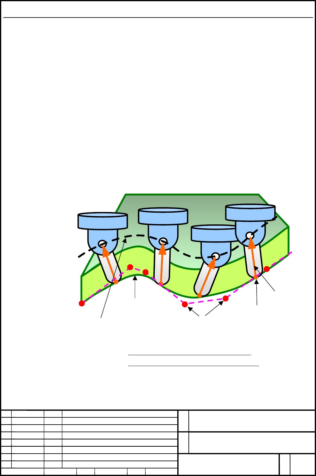
Command points
(NURBS control points)
Smooth curve is generated
from command points and
interpolated.
And tool center point moves
on the generated smooth
curve.
Tool center point
Tool length
compensation
Machine position of tool
moves so that it is distant
from the path of tool
center point by tool length
compensation.
Fig.1: NURBS interpolation for 5-axis machining
(with Tool center point control for 5-axis machining)
Contents Summary of FANUC Series 30i-A/31i-A5 NURBS Interpolation for 5-Axis Machining Additional Manual
- Page 1FANUC Series 30i-A/31i-A5 NURBS Interpolation for 5-axis Machining Specifications Name FANUC Series 30i-A/31i-A5 NURBS Interpolation for 5-axis Machining No. A-79985E Ed. Date Person Contents FANUC LTD. Page 1/5 Date 2005.03.11 Person Apprv.�
- Page 2CONTENTS OVERVIEW ..................................................................................................................................................... 3 FORMAT ...........................................................................................................................
- Page 3Overview Many computer-aided design (CAD) systems used to design metal dies for automobiles and airplanes utilize non-uniform rational B-spline (NURBS) to express a sculptured surface or curve for the metal dies. NURBS interpolation function enables NURBS curve expression to be directly specified to
- Page 4Format FORMAT G06.2 [P_] K_ X_ Y_ Z_ α_ β_ [R_] [F_] ; K_ X_ Y_ Z_ α_ β_ [R_] ; K_ X_ Y_ Z_ α_ β_ [R_] ; … K_ X_ Y_ Z_ α_ β_ [R_] ; K_ ; … K_ ; G01 … ; EXPLANATION G06.2 : Start NURBS interpolation mode P_ : Rank of NURBS curve X_ Y_ Z_ : Control point α_ β_ : Control point (rotary axes) R_ : Weight
- Page 5Explanation Explanation is same as the conventional NURBS interpolation. Restrictions Tool center point control for 5-axis machining NURBS interpolation for 5-axis machining can be used together with Tool center point control for 5-axis machining (type I: G43.4), but cannot be used together with Too