FANUC Series 30i-A/31i-A5 NURBS Interpolation for 5-Axis Machining Additional Manual Page 4
Additional Manual
4
/
5
Ed.
Apprv.
Person
Date
Person
Contents
Date
2005.03.11
Name No.
FANUC Series 30i-A/31i-A5
NURBS Interpolation for 5-axis Machining
A
-79985E
Page
FANUC LTD.
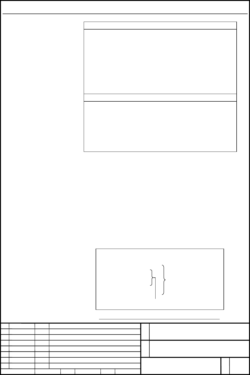
O0010
…
G43.4 H1 P0;
G06.2 K_ X_ Y_ Z_ B_ C_;
…
K_
G01 X_ Y_ Z_ B_ C_;
G49;
…
M30;
Format
FORMAT
G06.2 [P_] K_ X_ Y_ Z_ α_ β_ [R_] [F_] ;
K_ X_ Y_ Z_ α_ β_ [R_] ;
K_ X_ Y_ Z_ α_ β_ [R_] ;
…
K_ X_ Y_ Z_ α_ β_ [R_] ;
K_ ;
…
K_ ;
G01 … ;
EXPLANATION
G06.2 : Start NURBS interpolation mode
P_ : Rank of NURBS curve
X_ Y_ Z_ : Control point
α_ β_ : Control point (rotary axes)
R_ : Weight
K_ : Knot
F_ : Feedrate
Format for NURBS interpolation for 5-axis machining is same as that for the
conventional NURBS interpolation, but up to five axes that include two rotary
axes can be specified as the axis of NURBS interpolation.
When NURBS interpolation for 5-axis machining and Tool center point control
(type I: G43.4) are used together, Tool center point control (G43.4) should be
commanded first, and after that NURBS interpolation for 5-axis maching (G06.2)
should be commanded. When they are canceled, NURBS interpolation for 5-axis
machining should be canceled (G-code command in group 1 except for G06.2) first,
and after that Tool center point control should be canceled (G49).
Example)
NURBS interpolation for 5-axis machining
Tool center point control
for 5-axis machining
Fig.2: Program of NURBS interpolation for 5-axis machining
Contents Summary of FANUC Series 30i-A/31i-A5 NURBS Interpolation for 5-Axis Machining Additional Manual
- Page 1FANUC Series 30i-A/31i-A5 NURBS Interpolation for 5-axis Machining Specifications Name FANUC Series 30i-A/31i-A5 NURBS Interpolation for 5-axis Machining No. A-79985E Ed. Date Person Contents FANUC LTD. Page 1/5 Date 2005.03.11 Person Apprv.�
- Page 2CONTENTS OVERVIEW ..................................................................................................................................................... 3 FORMAT ...........................................................................................................................
- Page 3Overview Many computer-aided design (CAD) systems used to design metal dies for automobiles and airplanes utilize non-uniform rational B-spline (NURBS) to express a sculptured surface or curve for the metal dies. NURBS interpolation function enables NURBS curve expression to be directly specified to
- Page 4Format FORMAT G06.2 [P_] K_ X_ Y_ Z_ α_ β_ [R_] [F_] ; K_ X_ Y_ Z_ α_ β_ [R_] ; K_ X_ Y_ Z_ α_ β_ [R_] ; … K_ X_ Y_ Z_ α_ β_ [R_] ; K_ ; … K_ ; G01 … ; EXPLANATION G06.2 : Start NURBS interpolation mode P_ : Rank of NURBS curve X_ Y_ Z_ : Control point α_ β_ : Control point (rotary axes) R_ : Weight
- Page 5Explanation Explanation is same as the conventional NURBS interpolation. Restrictions Tool center point control for 5-axis machining NURBS interpolation for 5-axis machining can be used together with Tool center point control for 5-axis machining (type I: G43.4), but cannot be used together with Too