Dust collection unit for FANUC LASER C2000E, C4000E Additional Manual Page 2
Additional Manual
03 20030222 OHTA Addition of C2000-E
02 20030204 OHTA Addition of “6.Order pasts”
Funakubo
01 20021009 OHTA 1st edition
Funakubo
DRAW. NO.
A-81053E-035
CUST.
EDIT DATE DESIG. DESCRIPTION APPRO.
FANUC LTD
SHEET
1/5
TITLE:
Dusut collection unit
for FANUC LASER C4000-MODEL E
and C2000-MODEL E
Dust collection unit for FANUC LASER C4000-MODEL E and C2000-MODEL E
1. Abstract
The dust collection unit was added for the improvement of reliability and maintainability of C4000-E
and C2000-E. Because the dust of the particulate in the resonator can be divided by the centrifugal
force, the laser gas can be kept clean. Therefor, the decrease of the internal mirror damage and the
mirror cleaning cycle can be expected.
To prevent the power decrease because of the dust collection unit addition, the mesh of the turbo
blower filter was enlarged in C4000-E and C2000-E. Moreover, to have the interchangeability of the
turbo blower, this filter was excluded from the turbo blower. Therefor, the turbo blower filter has not
placed to the turbo blower to which the unit is shipped since following time. Please install either filter
after confirming the specification of the filter.
A04B-0800-C015 (for C4000-E) : July 2002
Turbo blower except above C015 : February 2003
Additionally, tube pressure for oscillation was changed from 66Torr to 68Torr in C2000-E.
Note) In FANUC LASER C1000-MODEL E, the effect of the dust collection unit is relatively few,
because the mirror cleaning cycle is long enough. Therefore, the dust collection unit is not
applied to C1000-E.
2. Arrangement
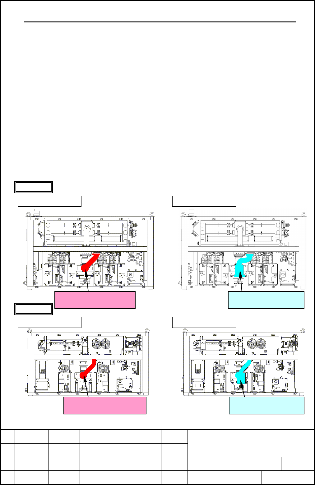
The dust collection unit is installed instead of the turbo blower outlet pipe shown in the figure below.
The screw and O ring are the same as the past composition.
C4000-E
Turbo blower outlet pipe
A
290-4540-V060
,
V061
Dust collection unit
A
290-4540-T060
,
T061
C2000-E
Turbo blower outlet pipe
A
290-4523-V060
,
V061
Dust collection unit
A
290-4523-T060
,
T061
New com
p
osition Past com
p
osition
New com
p
osition Past com
p
osition
Contents Summary of Dust collection unit for FANUC LASER C2000E, C4000E Additional Manual
- Page 1TECHNICAL REPORT(MANUAL) NO. TML 03/003E Date 24 June, 2003 General Manager of Laser Laboratory The modification for improvement of reliability and maintainability 1. Communicate this report to: ○ Your information only ○ GE Fanuc-N, GE Fanuc-E FANUC Robotics MILACRON ○ Machine tool builder Sales age
- Page 2Dust collection unit for FANUC LASER C4000-MODEL E and C2000-MODEL E 1. Abstract The dust collection unit was added for the improvement of reliability and maintainability of C4000-E and C2000-E. Because the dust of the particulate in the resonator can be divided by the centrifugal force, the laser g
- Page 33. Structure The dust box is arranged under the gas flow circuit, and dust is collected here. It is not necessary to maintain the dust box usually. However, please remove the dust box and the slit as shown in the figure below, and clean the inside of the dust box when a large amout of dust is genera
- Page 44. Change in tube pressure for oscillation In C2000-E, to prevent the power decrease because of the dust collection unit addition, tube pressure for oscillation was changed from 66Torr to 68Torr. The changed parameters are as follows. PRM15242(Tube pressure for oscillation 50Hz) 660→ 680 PRM15243(Tu
- Page 5Note) When you exchange the turbo blower, please remove the filter form the turbo blower installed the laser oscillator, and install this filter in the turbo blower for the exchange. Installed Returning turbo blower turbo blower Laser oscillator Filter 2) Installing filter Installed Installed Turbo
- Page 66. Application (1) Dust collection unit The dust collection unit is applied from following oscillator. C4000-E L02740475 (Manufacturing in 2002 in July) Note) The change of turbo blower filter is applied at the same time. C2000-E L02Z20684~L02Z20689, L02Z20692, L02Z20693 (Manufacturing in 2002 Decem