New Design of Digital Servo Software 9096 Series Additional Manual Page 8
Additional Manual
7/8
Descri
p
tion
Design.
DateEd
01.05.08
SHEET
DRAW. No.
CUST.
TITLE
Ihara
Newly designed
Notice of the new desig
n
of
Digital Servo Software 9096
series
A
-62449E-085
FANUC LTD
NOTE
In the case of two, or three axes amplifier, set same parameter value
to all the axes.
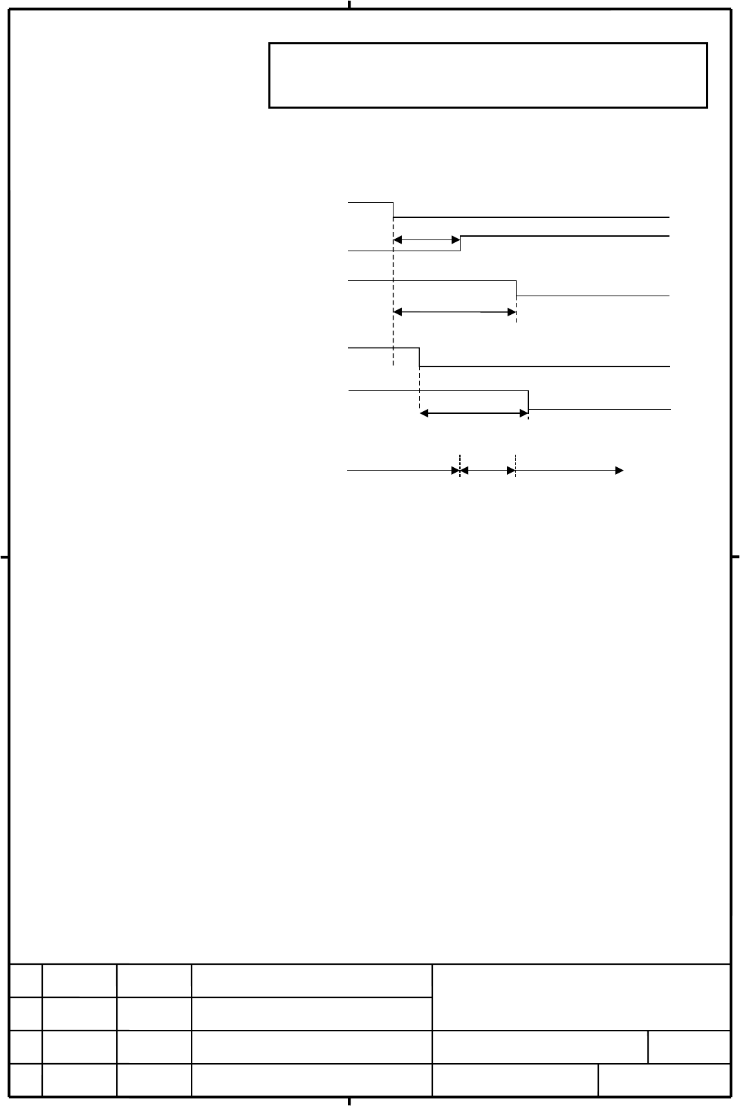
(4) Example of timing chart at brake contorol mode
ESP delay timer in αi series servo amplifier (50 to 400ms)
.
Al
arm o
r
emergency
stop signal
Mechanical
brake
Servo amplifier
MCC OFF
Brake control timer: Should be longer (approximately 200ms)
than the time (50 to 100ms) during which the mechanical
brake is applied.
50~100ms (approximately)
*ESP signal to
PSM (+24V)
The control current
sustains the tool.
The control current
and mechanical
brake sustain the
tool.
The mechanical brake
sustains the tool.
*ESP signal in
SVM
Contents Summary of New Design of Digital Servo Software 9096 Series Additional Manual
- Page 1TECHNICAL REPORT (MANUAL) No. TM 01/011 Date , 2001 General Manager of Servo Laboratory Notice of the new design of Digital Servo Software 9096/A(01) 1. Distribute this report to the destinations marked with Your information GE Fanuc-N, GE Fanuc-E Fanuc Robotics-NA, Fanuc Robotics-E CINCINNATI MILAC
- Page 2Notice of the new design of Digital Servo Software 9096 series 1. Type of applied documents Name FANUC AC SERVO MOTOR Alpha series Parameter manual Spec. No./Ver. A-62449E-085 2. Summary of Change Group Name / Outline New, Add Applicable Correct, Del Date Basic Function i 1. TUNE becomes available N
- Page 3Notice of the new design of Digital Servo Software 9096 series We report that Digital Servo Software 9096 series has been newly designed. Servo software 9096 series is necessary to use αi series with a system which uses servo card equipped with 320C52. When αi series is used with FS21i or PowerMate
- Page 4Attached 1. Parameter table for αi series servo motors Standard parameters for αi series servo motors are added to parameter table (See following Table 1-1 and Table 1-2) New motors are : α1/5000i, α2/5000i, αM2/5000i, αM3/5000i, αC4/3000i, α4/4000i, αC8/2000i, α8/3000i, αM8/4000i, αM12/4000i, αC12/
- Page 5[Table 1-1] Parameter table for HRV1 control (1) Motor Model α1 α2 αM2 αM3 αC4 α4 αC8 α8 αM8 αM12 αC12 5000i 5000i 5000i 5000i 3000i 4000i 2000i 3000i 4000i 4000i 2000i Motor specification 0202 0205 0212 0215 0221 0223 0226 0227 0235 0238 0241 Motor type No. 152 155 162 165 171 173 176 177 185 188 1
- Page 6[Table 1-2] Parameter table for HRV1 control (2) Motor Model α12 αC22 α22 αC30 α30 α40 αM22 αM30 αM40 3000i 2000i 3000i 1500i 3000i 3000i 4000i 4000i 4000i Motor specification 0243 0246 0247 0251 0253 0257 0265 0268 0272 Motor type No. 193 196 197 201 203 207 215 218 222 2001.04.01 Symbol Parameter
- Page 7Attached 2. Parameter setting for ESP delay timer in αi series servo amplifier (1) Overview αi series servo amplifier has delay timer (50ms to 400ms) to emergency stop signal (ESP) inside. This delay timer makes it possible to use Brake contorol function without external timer. See FANUC AC SERVO MO
- Page 8NOTE In the case of two, or three axes amplifier, set same parameter value to all the axes. (4) Example of timing chart at brake contorol mode Alarm or emergency stop signal 50~100ms (approximately) Mechanical brake Servo amplifier MCC OFF Brake control timer: Should be longer (approximately 200ms)
- Page 9Attached 3. Parameter setting for Dummy serial feedback function. (1) Overview The specification of Dummy serial feedback function is changed as follows. (2) Series and editions of applicable servo software Series 9096/A(01) or later (Series 21i, PowerMate i) (3) Setting parameters Setting the follo