Connecting and Maintenance Manual for Fanuc Intelligent Terminal (A-72891E/03) Additional Manual Page 3
Additional Manual
EDIT
•
•••••••••
SHEE
DRAW. NO. CUST
.
TITLE
DESCRIPTIONDESIG.DATE
FANUC Intelligent Terminal
Connectin
g
and Maintenance
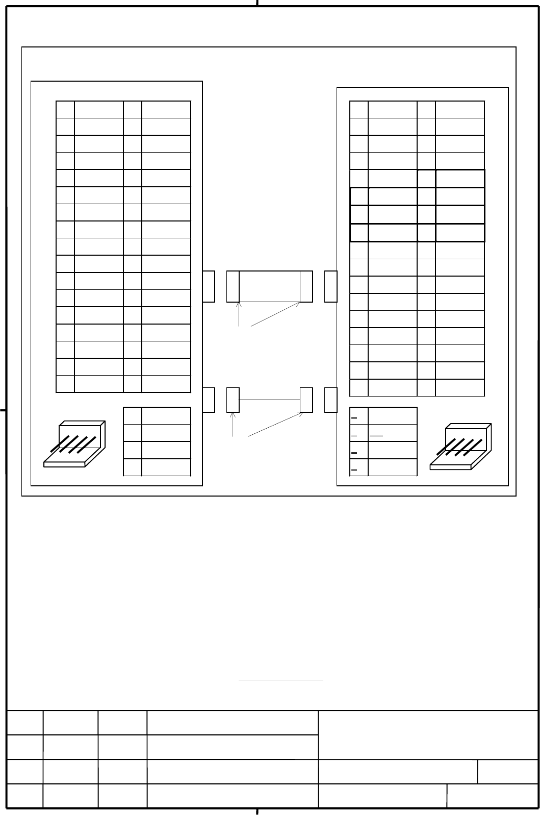
••••Floppy Disk Drive (Signal & Power)
Note 1) This is standard interface for IBM PC. But, please pay attention to the following points.
Only 2 modes 720K/1.44M bytes are available.
DENSEL is fixed
“
Low
”
level.
All floppy disk drives in the market do not need both +5VDC and +12VDC. When the floppy drive which needs
DC+12V input is used, please pay attention to the current requirement.
Note 2) All floppy disk drives do not fit to I.T. Careful checking is required on the I.T. And please pay attention to another
point that floppy disk drives in the market are not almost considered about waterproof and dustproof.
Note 3) The figure shows a sample drive interface. Design the cable to suit the interface of the actual drive to be
connected.
Note 4) Recommended Cable is as follows. (Cable length is 1.0m)
A02B-0207-K801
011
/
03
Added and modified
p
art of
10V 2DENSEL
30V 4
50V 6
70V 8*INDEX
90V 10*MT0
11 0V 12 *D S1
13 0V 14 *D S0
15 0V 16 *M T1
17 0V 18 *D IR
19 0V 20 *ST E P
21 0V 22 *W D A TA
23 0V 24 *W E
25 0V 26 *TR K 0
27 0V 28 *W P R T
29 0V 30 *R D A TA
31 0V 32 H D SE L
33 0V 34 *D SK C H
1 +12V
20V
30V
4+5V
10V 2DENSEL
30V 4
50V 6
70V 8*INDEX
90V 10*DS0
11 0V 12 *D S1
13 0V 14 (R eserve)
15 0V 16 *M TR O N
17 0V 18 *D IR
19 0V 20 *ST E P
21 0V 22 *W D A T A
23 0V 24 *W E
25 0V 26 *TR K 0
27 0V 28 *W P R T
29 0V 30 *R D A TA
31 0V 32 H D SE L
33 0V 34 *D SK C H
1 4(NC)
2 30V (NC)
3 20V
4 1+5V
YAM AICHI ID C type
F A S-34-17
AM P EI series 4 pin
Housing 171822-4
Contact 170262,170263
1 2 3 4
In telligent Term inal Type
3.5” Floppy Disk Drive A
‚b‚c‚R‚S
CN2
4 3 2 1
‡B
Contents Summary of Connecting and Maintenance Manual for Fanuc Intelligent Terminal (A-72891E/03) Additional Manual
- Page 1TECHNICAL REPORT (MANUAL) Date 1998 General Manager of Hardware Laboratory Connecting and Maintenance Manual for FANUC Intelligent Terminal Communicate this report to: ○ Your information only ○ GE Fanuc-N, GE Fanuc-E FANUC Robotics CINCINNATI MILACRON ○ Machine tool builder Sales agency End user Sum
- Page 2INTRODUCTION This manual describes the connecting information of the Fanuc Intelligent Terminal Type 1 function (I.T.) of the following FANUC CNC. This manual also provides maintenance information (block diagrams and drawing numbers of printed circuit board(PCB), etc.). Use this manual together with
- Page 3••••Floppy Disk Drive (Signal & Power) Intelligent Term inalType 3.5” Floppy D isk D rive A ‚‚b‚ cR‚ S 1 0V 2 D E N SE L 1 0V 2 D E N SE L 3 0V 4 3 0V 4 5 0V 6 5 0V 6 7 0V 8 *IN D E X 7 0V 8 *IN D E X 9 0V 10 *M T0 9 0V 10 *D S0 11 0V 12 *D S1 11 0V 12 *D S1 13 0V 14 *D S0 13 0V 14 (R eserve) 15 0V
- Page 4Cable Wiring JD 8 J1 1 1 1 0V 0V 2 2 2 D E N SE L D E N SE L 3 3 3 0V 0V 4 4 4 (N C ) (N C ) 5 5 5 0V 0V 6 6 6 (N C ) (N C ) 7 7 7 0V 0V 8 8 8 *IN D EX *IN D EX 9 9 9 0V 0V 10 10 16 *M T0 *D S0 11 11 15 0V 0V 12 12 14 *D S1 *D S1 13 13 13 0V 0V 14 14 12 *D S0 (R eserve) 15 15 11 0V 0V 16 16 10 Panne