Connecting and Maintenance Manual for Fanuc Intelligent Terminal (A-72891E/03) Additional Manual Page 4
Additional Manual
EDIT
•
•••••••••
SHEE
DRAW. NO. CUST
.
TITLE
DESCRIPTIONDESIG.DATE
FANUC Intelligent Terminal
Connectin
g
and Maintenance
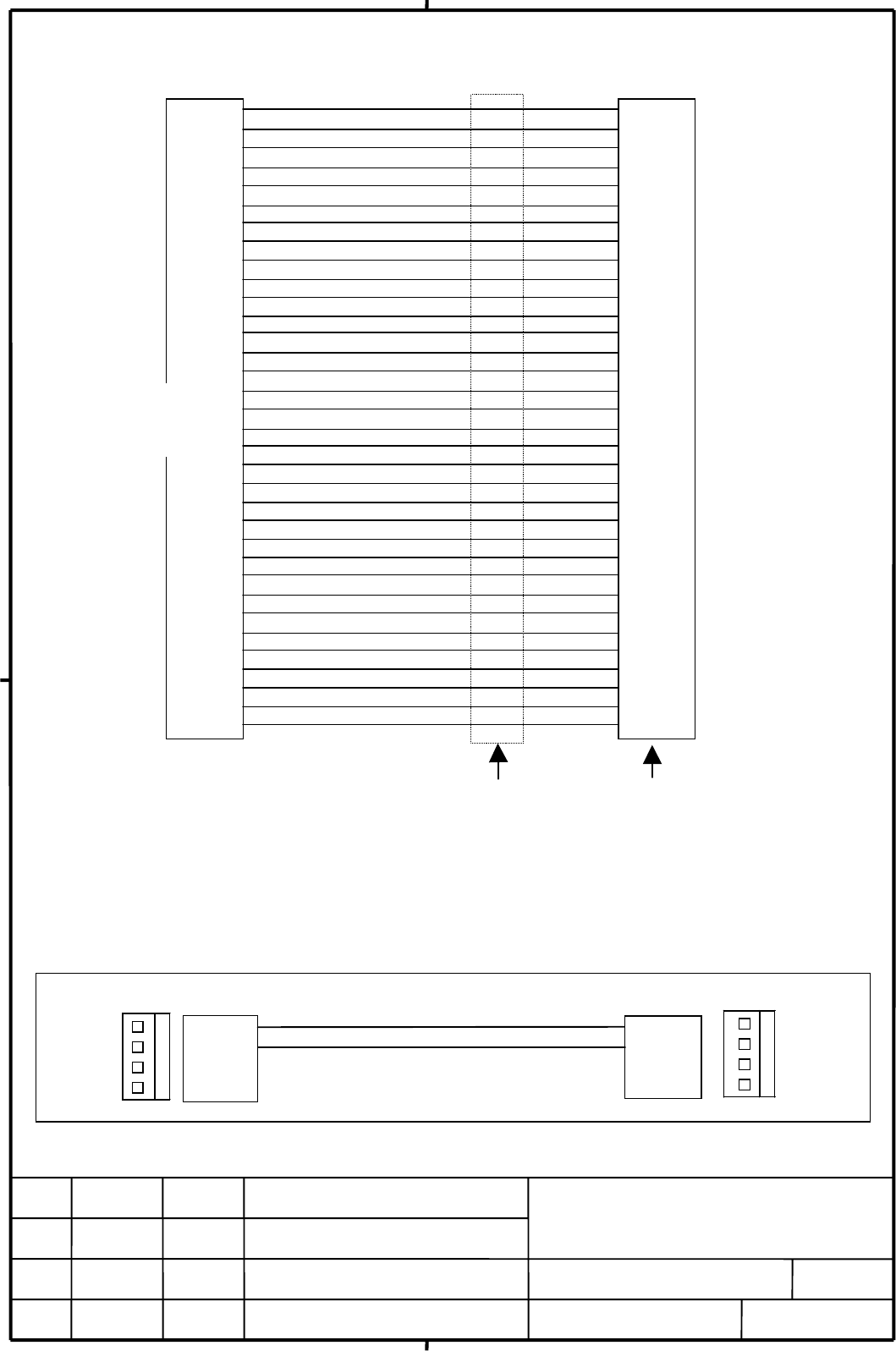
Cable Wiring
FDD interface is standard one for IBM PC. The connecting cable which can be gotten in the market is twisted from 10th pin
to 16th pin between the I.T. (PC) and a Drive A.
In this case, the drive number plug of FDD must be set
“
DRIVE 1
”
(Second Drive).
2) Power Cable Wiring
012
/
03
Added and modified
p
art of
+5V
0V
(NC)
(NC)
J2
+5V
0V
0V
+12V
CN2
C N 2
+5V
0V
0V
+12V
4
3
2
1
J2
1
2
3
4
+5V
0V
(NC)
(NC)
1
2
3
4
1
2
3
4
0V
DENSEL
0V
(NC)
0V
(NC)
0V
*IN D E X
0V
*M T 0
0V
*D S1
0V
*D S0
0V
*M T 1
0V
*D IR
0V
*ST E P
0V
*W D A T A
0V
*W E
0V
*T R K 0
0V
*W PR T
0V
*R D A T A
0V
HDSEL
0V
*D SK C H
0V
DENSEL
0V
(NC)
0V
(NC)
0V
*IN D E X
0V
*D S0
0V
*D S1
0V
(R eserve)
0V
*M T R O N
0V
*D IR
0V
*ST E P
0V
*W D A T A
0V
*W E
0V
*T R K 0
0V
*W PR T
0V
*R D A T A
0V
HDSEL
0V
*D SK C H
i
Refer to th e figure o
f
previou s page about
th e pin assignm ents
j
Pannel Mount Type
3.5" Floppy Disk
Unit
In telligent
Term inal
P.C.B.
Drive B
Drive A
1
2
3
4
5
6
7
8
9
10
11
12
13
14
15
16
17
18
19
20
21
22
23
24
25
26
27
28
29
30
31
32
33
34
1
2
3
4
5
6
7
8
9
16
15
14
13
12
11
10
17
18
19
20
21
22
23
24
25
26
27
28
29
30
31
32
33
34
J1JD 8
1
2
3
4
5
6
7
8
9
10
11
12
13
14
15
16
17
18
19
20
21
22
23
24
25
26
27
28
29
30
31
32
33
34
Contents Summary of Connecting and Maintenance Manual for Fanuc Intelligent Terminal (A-72891E/03) Additional Manual
- Page 1TECHNICAL REPORT (MANUAL) Date 1998 General Manager of Hardware Laboratory Connecting and Maintenance Manual for FANUC Intelligent Terminal Communicate this report to: ○ Your information only ○ GE Fanuc-N, GE Fanuc-E FANUC Robotics CINCINNATI MILACRON ○ Machine tool builder Sales agency End user Sum
- Page 2INTRODUCTION This manual describes the connecting information of the Fanuc Intelligent Terminal Type 1 function (I.T.) of the following FANUC CNC. This manual also provides maintenance information (block diagrams and drawing numbers of printed circuit board(PCB), etc.). Use this manual together with
- Page 3••••Floppy Disk Drive (Signal & Power) Intelligent Term inalType 3.5” Floppy D isk D rive A ‚‚b‚ cR‚ S 1 0V 2 D E N SE L 1 0V 2 D E N SE L 3 0V 4 3 0V 4 5 0V 6 5 0V 6 7 0V 8 *IN D E X 7 0V 8 *IN D E X 9 0V 10 *M T0 9 0V 10 *D S0 11 0V 12 *D S1 11 0V 12 *D S1 13 0V 14 *D S0 13 0V 14 (R eserve) 15 0V
- Page 4Cable Wiring JD 8 J1 1 1 1 0V 0V 2 2 2 D E N SE L D E N SE L 3 3 3 0V 0V 4 4 4 (N C ) (N C ) 5 5 5 0V 0V 6 6 6 (N C ) (N C ) 7 7 7 0V 0V 8 8 8 *IN D EX *IN D EX 9 9 9 0V 0V 10 10 16 *M T0 *D S0 11 11 15 0V 0V 12 12 14 *D S1 *D S1 13 13 13 0V 0V 14 14 12 *D S0 (R eserve) 15 15 11 0V 0V 16 16 10 Panne