TERMINAL TYPE I/O MODULE CONNECTING MANUAL Additional Manual Page 12
Additional Manual
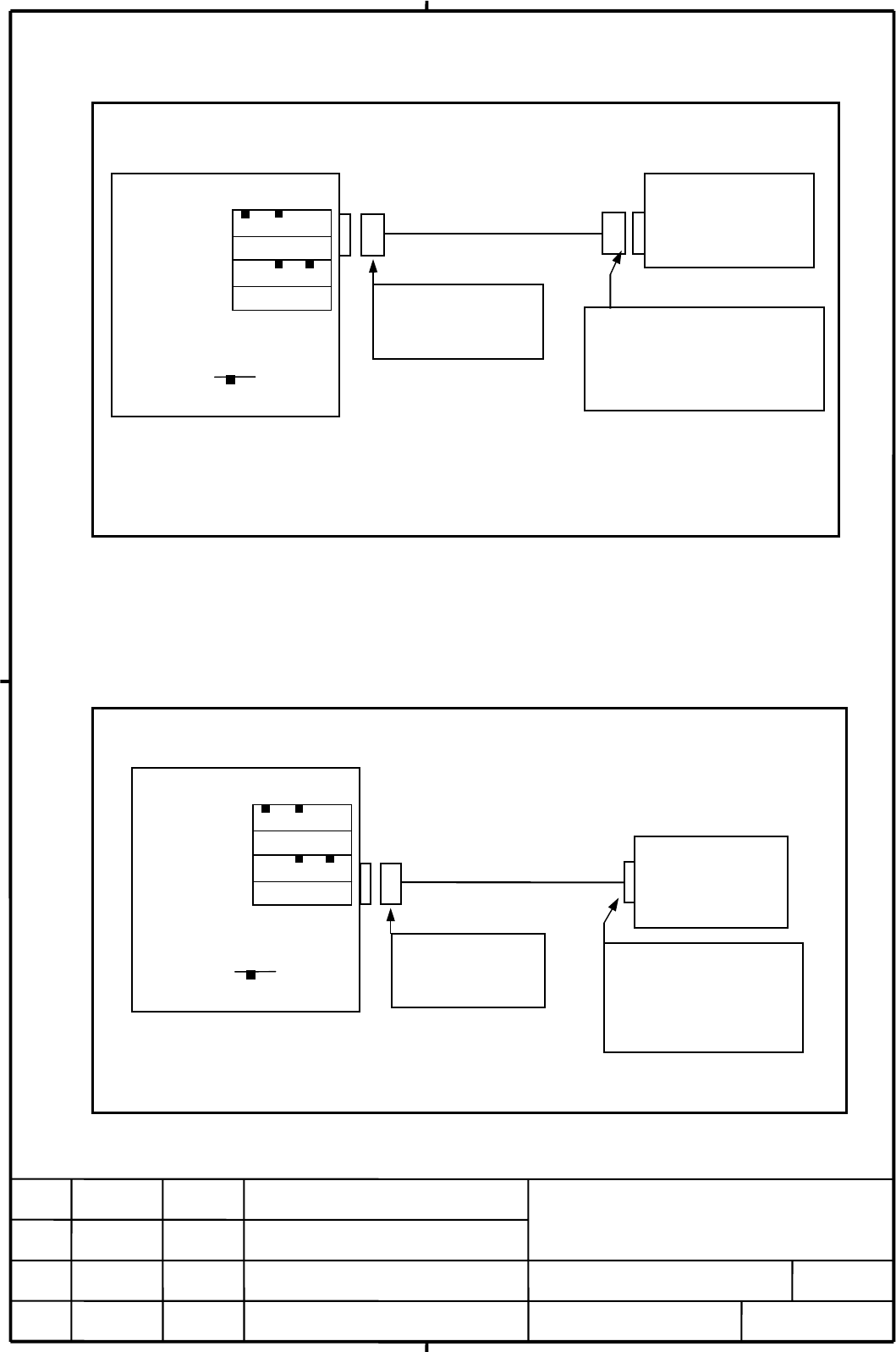
4.2 Connecting Input power source
Supply power to this unit from CNC or external resource.
The 24V DC input to CP11A(A1,A2) can be output from CP11B(B1,B2) for use
branchimg. The connection of CP11B(B1,B2) is as shown below. In this case, the
external 24V DC power supply should have a rating which is equal to the sum of the
current consumed by the control unit and the current used via CP11B(B1,B2).
12
/
TERMINAL TYPE I/O MODULE
CONNECTING MANUAL
EDIT
FANUC
SHEET
DRAW. NO.
CUST
TITLE
DESCRIPTION DESIG. DATE
External device
C
P 1B1
Ke
y
arran
g
ement
Input
A3 A2 A1
0V +24V
CP11
A
Output
0V +24E
B3 B2 B1
Basic module
Connect for external device
of the external device.
Select a connector that
matches the pin layout
Tyco Electronics AMP
2-178288-3 (housing)
1-175218-5 (contact)
Ke
y
arran
g
ement
(Crimp terminal of size M3 is available on the external power side)
Recommended cable (using external power) : A02B-0124-K830(5m)
24VDC stabilized
power
(24VDC±10%)
CP 1B 1
Select a source that meets
the external power terminal
Tyco Electronics AMP
1-178288-3 (housing)
1-175218-5 (contact)
Output
A3 A2 A1
0V +24V
0V +24E
B3 B2 B1
Input
CP11
A
Connect for input
External power Basic module
A-86491E
Contents Summary of TERMINAL TYPE I/O MODULE CONNECTING MANUAL Additional Manual
- Page 1FANUC TERMINAL TYPE I/O MODULE CONNECTING MANUAL Table of contents 4.4 Power turn-off sequence 1. Outline 4.5 Signal assignment on terminal block 4.6 Connection of DI / DO 2. Specification of module 4.6.1 Connection of DI 2.1 Ordering specification 4.6.2 Connection of DO 2.2 Environmental conditions
- Page 21. Outline Specification of terminal type I/O module is based on connector panel I/O module. The strong points of terminal type I/O module are below. - Using ferrule terminal for connect input/output signal. - LED which indicates On/Off state every input/output signal. - 16 points of digital output
- Page 32.Specification of module 2.1 Ordering specification Name Ordering specification Specification of module Basic module A03B-0823-C001 DI 24pt / DO 16pt With I/O Link I/F Extension module A A03B-0823-C002 DI 24pt / DO 16pt With MPG I/F Note) Connect extension module A next to basic module. Extension m
- Page 42.3 Specification of I/O signals Digital input Digital output Point 24 points Point 16 points Common 8 points/common Common 8 points/common (Common terminals (Common terminals are 6 points. ) are 8 points. ) Ratings input 24VDC±10% Ratings output 12~24VDC (+20%,-15%) voltage voltage Ratings input 7.
- Page 53.Outer dimensions 3.1 Outer dimensions (Each module commonness) Unit:mm At maximum composition ( 1 Basic module and 3 Extension modules ) 280 150 TITLE TERMINAL TYPE I/O MODULE CONNECTING MANUAL DRAW. NO. CUST A-86491E SHEET EDIT DATE DESIG. DESCRIPTION FANUC 5/16�
- Page 63.2 Mounting and dismounting 3.2.1 Cautions for mounting module (1) Use the unit in a completely sealed cabinet. (2) Mount the unit on a vertical surface, and allow a space of at least 100 mm above and below the unit. Do not place any unit generating a large amount of heat under the detector interfa
- Page 73.2.3 Using DIN rail for mounting How to mount DIN rail The rock 1.Place the hook of the unit on the top end of the DIN rail 2.Push in the unit firmly until it clicks. Note) Please note that the lock doesn't remain falling. How to remove DIN rail 1. Pull down the look on the unit using a flat-blade
- Page 83.3 Name of each part on module 3.3.1 Basic module A03B-0823-C001 A (Refer to the LED which indicates state of DI/DO figure below.) T2 : Terminal for DO T1 : Terminal for DO T4 : Terminal for DI T3 : Terminal for DI JD1A (I/O LINK) CP11A Connector for input power supply JD1B (I/O LINK) CP11B Connect
- Page 93.3.2 Expansion module A A03B-0823-C002 A (Refer to the LED which indicates state of DI/DO figure below.) T2 : Terminal for DO T1 : Terminal for DO T4 : Terminal for DI T3 : Terminal for DI JA3 (MPG) Rotary switch Figure seen from direction of A of above figure CA105 Connector for expansion cable (
- Page 103.3.3 Expansion module B A03B-0823-C003 A (Refer to the LED which indicates state of DI/DO figure below.) T2 : Terminal for DO T1 : Terminal for DO T4 : Terminal for DI T3 : Terminal for DI Rotary switch Figure seen from direction of A of above figure CA105 Connector for expansion cable ( To the nex
- Page 114. Connection 4.1 General connection diagram CNC I/O Link FANUC I/O Link JD1B JD1A JD1A Such as I/O Unit Power supply for Load 24VDC JD1B JD1A T1 Relay, etc. Power supply CP11A DO 16pt Terminals Basic module T2 Relay, etc. External device CP11B Switch, etc. T3 DI 24pt Extension CA105 T4 Switch, etc.
- Page 124.2 Connecting Input power source Supply power to this unit from CNC or external resource. Basic module External power Connect for input 24VDC stabilized CP11A power A3 A2 A1 Input (24VDC±10%) 0V +24V B3 B2 B1 Output 0V +24E Tyco Electronics AMP CP11B 1-178288-3 (housing) 1-175218-5 (contact) Select
- Page 134.3 Power turn-on sequence Turn on the power to this unit in the following order or simultaneously. 1. Power supplies (200 VAC) for the entire machine (including the servo amplifier) 2. Power supplies (24 VDC) for terminal type I/O module and the FANUC I/O Link slave devices (such as the I/O Unit-MO
- Page 144.5 Signal assignment on terminal block (Each module commonness) Signal assignment for output T1 T2 1 DOCOM0 1 DOCOM0 2 Yn+0.0 2 Yn+0.1 3 0V-0 3 0V-0 4 Yn+0.2 4 Yn+0.3 5 Yn+0.4 5 Yn+0.5 6 0V-0 6 0V-0 7 Yn+0.6 7 Yn+0.7 8 DOCOM1 8 DOCOM1 9 Yn+1.0 9 Yn+1.1 10 0V-1 10 0V-1 11 Yn+1.2 11 Yn+1.3 12 Yn+1.4
- Page 154.6 Connection of DI / DO (Each module commonness) 4.6.1 Connection of DI Internal Signal name Terminal name and pin number of terminal block DICOM T3-1 DICOM T3-6 DICOM T3-11 DICOM T4-1 DICOM T4-6 DICOM T4-11 Xm+0.0 T3-2 I Xm+0.1 T4-2 I Xm+0.2 T3-3 I I Input circuit Xm+0.3 T4-3 I Xm+0.4 T3-4 I LED
- Page 16Internal 4.6.2 Connection of DO Terminal name and pin number of terminal block Signal name DOCOM0 T1-1 DOCOM0 T2-1 L Yn+0.0 T1-2 O L Yn+0.1 T2-2 O L Yn+0.2 T1-4 O + L Yn+0.3 T2-4 O Power supply for LOAD L Yn+0.4 T1-5 O L Yn+0.5 T2-5 O - L Yn+0.6 T1-7 O L Yn+0.7 T2-7 O 0V-0 T1-3 0V-0 T2-3 0V-0 T1-6 0
- Page 174.7 Connection between modules A way to connect between each modules are same way. The flat cable is connected with the connector (CA105, CA106) that mounted in each modules as shown in the figure below. In that case, please connect all of the 52 pins carefully in the direction of the connector. Ext
- Page 184.8 Connection of manual pulse generator An example in which three manual pulse generators are connected to expansion module A is shown below. The manual pulse generator can be connected only for the i series CNC. Recommended wire material:A66L–0001–0286 (#20 AWG × 6 + #24 AWG × 3 pairs) Recommended
- Page 19Note) The number of connectable manual pulse generators depends on the type and option configuration. Cable Length for Manual Pulse Generator TITLE TERMINAL TYPE I/O MODULE CONNECTING MANUAL DRAW. NO. CUST A-86491E SHEET EDIT DATE DESIG. DESCRIPTION FANUC 19/�
- Page 204.9 How to connect wire to the terminal (1) Insert a screwdriver whose up-to-date width is about 2.5mm into the clamp of the terminal block, and open the fixing bracket. Flat–bladed screwdriver The clamp Use recommendation flat–bladed screwdriver Weidmuller : Product number SDI 0.4X2.5X80 (2) Insert
- Page 214.10 Detaching of the terminal The terminal block can be detached from the module by loosening the installation screw at both ends of the terminal block. The installation screw Terminal block The installation screw The torque of the installation screw : 0.4Nm (max). TITLE TERMINAL TYPE I/O MODULE CO
- Page 225 Setting 5.1 DI/DO map on the I/O Link Basically, terminal type I/O module is allocated a group of DI addresses (16 bytes) and a group of DO addresses (8 bytes). Up to three hardware expansion modules can be added or removed as required. The reason for this address allocation is explained below. Th
- Page 235.2 DO (output signal) alarm detection The DO driver of the Basic and Expansion module A/B is capable of detecting an overcurrent and measuring its own temperature. If an accident, such as the connecting of the cable to ground, causes an abnormal increase in the load current or in the driver tempera
- Page 24Method of setting (control and method of setting the control) As shown below, the control (rotary switch) is located on an expansion module. To change the setting, turn the switch with a flat–bladed screwdriver with a tip width of about 2.5 mm. This is the standard setting. The function of the rotar
- Page 25Examples of setting TITLE TERMINAL TYPE I/O MODULE CONNECTING MANUAL DRAW. NO. CUST A-86491E SHEET EDIT DATE DESIG. DESCRIPTION FANUC 25/�
- Page 266. How to increase the number of common terminals Mounting terminal stand on the market on the top cover of extension module, it is possible to increase the number of common terminals. Additional terminal Example of terminal on the market Maker name Type case Number of maximum poles WAGO 869 series
- Page 27Installation size of additional terminal Unit:mm Use the M3 tap screw of 10mm or less in length for the fixation of the additional terminal. TITLE TERMINAL TYPE I/O MODULE CONNECTING MANUAL DRAW. NO. CUST A-86491E SHEET EDIT DATE DESIG. DESCRIPTION FANUC 27/�
- Page 287. Others 7.1 DO signal reaction to a system alarm If a system alarm occurs in a CNC using terminal type I/O module, or if I/O Link communication between the CNC and terminal type I/O module fails, all the DO signals of the I/O module are turned off. Therefore, due care must be taken when setting up