Element of Decomposition of Oil Mist for Fanuc Laser C Series Additional Manual Page 3
Additional Manual
02 20030313 T.WATANABE
C1000-E,C2000-E addition
01 20030217 T.WATANABE
1st edition
DRAW. NO.
A-81053E-034
CUST.
EDIT DATE DESIG. DESCRIPTION APPRO.
FANUC LTD
SHEET
002/5
3.Order Parts
①In case of addition newly
C4000-E C2000-E C1000-E
Specification Q'ty Specification Q'ty Specification Q'ty
Elem. of Decompos.
of Oil Mist
A290-4540-V170 2 A290-4523-V170 2 A290-4523-V170 2
O-ring JB-OR4D-G45 2 JB-OR4D-G45 2
A98L-0001-0619
#2031
2
Sticker A370-1146-0575 1 A370-1146-0575 1 A370-1146-0575 1
②In case of exchanging
C4000-E C2000-E C1000-E
Specification Q'ty Specification Q'ty Specification Q'ty
Elem. of Decompos.
of Oil Mist
A290-4540-V170 2 A290-4523-V170 2 A290-4523-V170 2
O-ring JB-OR4D-G45 2 JB-OR4D-G45 2
A98L-0001-0619
#2031
2
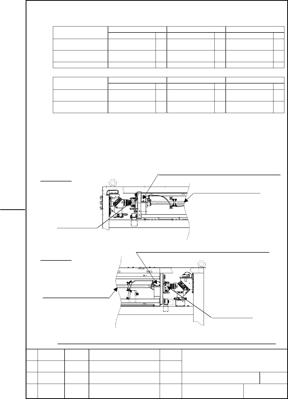
4.Procedure of addition of the Element of Decomposition of Oil Mist newly. (C2000-E,C1000-E)
① Get the mode barn of laser beam before exchange or installation of the Element
of Decomposition of Oil Mist.
② Remove the flange.
③ Install new Element of Decomposition of Oil Mist. If O-ring is damaged, exchange the O-ring.
④ Check the Leakage of laser gas. And do the discharge aging.
⑤
Get the mode barn of laser beam, and make sure there is no change in the beam mode form.
⑥
Please stick a sticker on a panel. (Refer to clause 8)
C1000-E
No.1 No.2 dischar
g
e tube
Flange (2places)
Elem.of Decompos. of Oil mist mounting position
OC, RM
Fig.2 The Element of Decomposition of Oil Mist mounting diagram (C1000-E,C2000-E)
C2000-E
Flange (2places)
Elem.of Decompos. of Oil mist mounting position
OC,RM
No.3 No.4 dischar
g
e tube
TITLE
Element of Decomposition of Oil Mist
for FANUC LASER C series
Contents Summary of Element of Decomposition of Oil Mist for Fanuc Laser C Series Additional Manual
- Page 1TECHNICAL REPORT(MANUAL) NO. TML 03/003E Date 24 June, 2003 General Manager of Laser Laboratory The modification for improvement of reliability and maintainability 1. Communicate this report to: ○ Your information only ○ GE Fanuc-N, GE Fanuc-E FANUC Robotics MILACRON ○ Machine tool builder Sales age
- Page 2ELEMENT OF DECOMPOSITION OF OIL MIST for FANUC LASER C series 1.Outline The Element of Decomposition of Oil Mist that decomposes oil mist in resonator is added to the C1000-E,C2000-E and C4000-E to decrease the resonator mirror pollution, and to extend the mirror cleaning cycle. Please maintain the
- Page 33.Order Parts ①In case of addition newly C4000-E C2000-E C1000-E Specification Q'ty Specification Q'ty Specification Q'ty Elem. of Decompos. A290-4540-V170 2 A290-4523-V170 2 A290-4523-V170 2 of Oil Mist A98L-0001-0619 O-ring JB-OR4D-G45 2 JB-OR4D-G45 2 2 #2031 Sticker A370-1146-0575 1 A370-1146-057
- Page 45.Procedure of additon of the Element of Decomposition of Oil Mist newly. (C4000-E) ① Get the mode barn of laser beam before exchange or installation of the Element of Decomposition of Oil Mist. ② Stop the cooling water by not only shut down of electrical power but shut off the valve of water line.
- Page 58.About the display which shows that the Element of Decomposition of Oil Mist has already been applied. The sticker (Figure 4) shows that the Element of Decomposition of Oil Mist and other parts for enhancement of reliability and maintainability are installed in the oscillator. And it is pasted in t
- Page 69.Exchange of the Element of Decomposition of Oil Mist ・The life of the Element of Decomposition of Oil Mist is approx.10000 hours. Please exchange every 10000 hours. ・The Element of Decomposition of Oil Mist(C1000-E:A290-4514-V170,C2000-E:A290-4523-V170,C4000-E:A290-4540-V170) is adjusted a center