FS 16-LB, 16i-LA, 16i-LB, External Power Control Function Specifications Additional Manual Page 3
Additional Manual
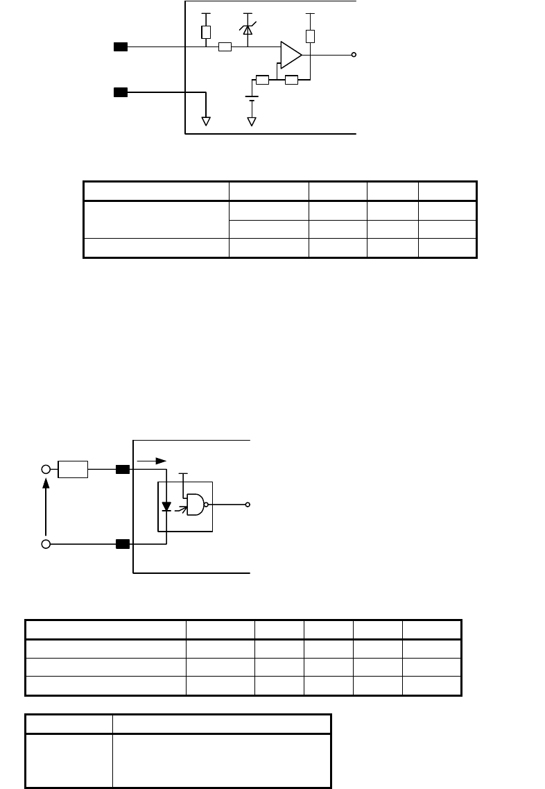
The receiver circuit of the external signal and recommended parameters are
shown below. And laser oscillator S/N that this circuit is installed is shown on
the right side. Specifications of this IF PCB are A16B-2100-0140 and -0141.
(4)
-
+
CN5#07
CN5#08
EXTP
EXTN
Fig.2 Receiver for External Pulse train
Symbol Min Max
Unit
Vth(high) 3.0 -
V
Threshold Voltage
Vth(low) - 2.1
V
Signal pulse width
- 0.1 -
msec
(Note)
On some old oscillator, below receiver circuit of the external signal is installed.
The recommended parameters and oscillator S/N are shown below.
Specification of this IF PCB is A02B-0128-C202.
This PCB is mounted on the oscillator for JAPAN and USA, not for CE Marking.
Parameter Symbol Min. Typ. Max Unit
Signal pulse voltage Vin 4 5 18 V
Signal pulse current Iin 10 12 20 mA
Signal pulse width - 0.1 - - msec
Rin Iin
EXTP
EXTN
CN5#01
CN5#02
V
in
Never fail to insert
the resistor Rin on the (+) side
(CN05#01), the resistivity of
which can be calculated
according to the equation,
Rin = (Vin - 1.8) / Iin
Fig.3 Receiver for External Pulse train
(2)
(2)
(2)
Model Application Serial Number
C1500B L96215063 - L97615367
C2000B L96220365 - L97620548
C3000C L96230231 - L97630348
(4)
3/5
Contents Summary of FS 16-LB, 16i-LA, 16i-LB, External Power Control Function Specifications Additional Manual
- Page 1FANUC Series 16-LB, 16i-LA, 16i-LB (4) External Power Control Function Specifications 04 Dec 05, 2002 Add. Model on Page 1 Add. New circuit and S/N on Page 3 03 Apr 25, 1995 Revision of Figure on Page 4 Add. Parameter on Page 5 02 Apr 7, 1995 Revision of description on Page 2-5 01 Mar 9, 1995 Newly
- Page 21. General The switching of the laser power, which is turned on by CNC, is possible by feeding the external on/off signal to the interface PCB of the laser oscillator. Using this function, the external control of the laser power can be performed introduc ing the pulse train signal, which is controll
- Page 3(4) The receiver circuit of the external signal and recommended parameters are shown below. And laser oscillator S/N that this circuit is installed is shown on the right side. Specifications of this IF PCB are A16B-2100-0140 and -0141. CN5#07 EXTP - + CN5#08 EXTN Fig.2 Receiver for External Pulse tr
- Page 42.2 Function (1) Outline When the external power control trigger signal (EPC) is "1", the CNC, provided that it can undergo the external power control, accepts this signal and is set EXTERNAL POWER CONTROL MODE. In this mode, the feedback power control is disabled and so is the monitoring of the ala
- Page 5* Pulse duty/frequency override (automatically disabled) * Edge cutting/start up function (pulsing disabled) * Conventional power control function (pulsing disabled) (3) Signals External power control trigger signal EPC