FS 16i/18i/21i-MA/MB/TA/TB, 18i-MB5, Periodical secondary pitch error compensation Additional Manual Page 8
Additional Manual
4. Parameter
14985 Number of the farthest periodical secondary pitch error compensation point
in the negative direction for each axis.
[Data type] Word axis
[Data unit] number
[Valid data range] 0-1023
The compensation point specified with this parameter is used as a reference point
for periodical secondary pitch error compensation. This reference point is used as a
compensation point at the reference position. The compensation value at the
compensation reference point must be 0.
14986 Number of the farthest periodical secondary pitch error compensation point
in the positive direction for each axis
[Data type] Word axis
[Data unit] number
[Valid data range] 0-1023
Set the number of the fathest periodical secondary pitch error compensation point
in the positive direction for each axis.
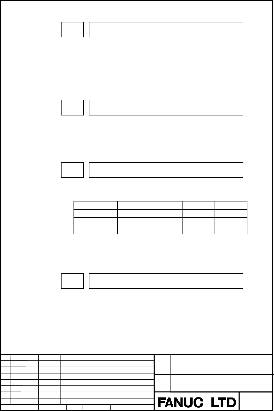
14987 Interval between periodical secondary pitch error compensation points for
each axis
[Data type] 2 word axis
[Data unit]
Input increment IS-A IS-B IS-C Unit
Input in mm 0.01 0.001 0.0001 mm
Input in inches 0.001 0.0001 0.00001 inch
Rotation axis 0.01 0.001 0.0001 deg
[Vaild data range] From 0 through the space between neiboring points of the pitch error
compensation (parameter no.3624).
Set hte interval between periodical secondary pitch error compensation poins for
each axis.
14988 Magnification for periodical secondary pitch error compensation for each
axis
[Data type] Byte axis
[Valid data range] 0 - 100
Set a magnificatino for periodical secondary pitch error compensation for each axis.
When 1 set as the magnification for periodical secondary pitch error compensation ,
the unit of compensation data is the same as the detection unit.
Edit
Apprv.
Desig.
Sheet
Title
Draw
No.
Date
Design
Description
Date
FANUC Series 16i/18i-MA/MB, 18i-MB5
FANUC Series 16i/18i-TA/TB
Periodical secondary pitch error compensation
A-78868E
2003.04.11
Egashira
7/8
Contents Summary of FS 16i/18i/21i-MA/MB/TA/TB, 18i-MB5, Periodical secondary pitch error compensation Additional Manual
- Page 1TECHNICAL REPORT (MANUAL) No. TMN03/039E Date : Apr. 24, 2003 General Manager of Software Development Center FANUC Series 16i/18i/21i-MA/MB/TA/TB, 18i-MB5 Periodical secondary pitch error compensation 1. Communicate this report to: Your information only ○ GE Fanuc-N, GE Fanuc-E FANUC Robotics MILACR
- Page 2FANUC Series 16i/18i-MA/MB FANUC Series 18i-MB5 FANUC Series 16i/18i-TA/TB Periodical secondary pitch error compensation Specifications FANUC Series 16i/18i-MA/MB, 18i-MB5 Title FANUC Series 16i/18i-TA/TB Periodical secondary pitch error compensation Draw No. A-78868E Edit Date Design Description Sh
- Page 3Index 1. Overview 3 2. Explanation 3 3. Example 5 4. Parameter 7 5. Caution 8 FANUC Series 16i/18i-MA/MB, 18i-MB5 Title FANUC Series 16i/18i-TA/TB Periodical secondary pitch error compensation Draw No. A-78868E Edit Date Design Description Sheet 2/8 Date 2003.04.11 Desig. Egashira Apprv.�
- Page 41.1 Periodical secondary pitch error compensation 1. Overview When a rotary table is rotated using a gear, there are two cycles of the occurrence of pitch errors. One cycle is the same as that of the rotation of the rotary table while the other is the same as that of the rotation of the gear for rot
- Page 5Although a rotary table is used as an example here, periodical secondary pitch error compensation can be used in the same way when the machine is moved along a linear axis using a gear. For example, in a configuration such as that shown in Fig 1.1(c), stored pitch error compensation is used for the
- Page 63. Example When a rotary table is rotated using a gear, a pitch error relative to the cycle of the rotation of the rotary table occurs, as does a pitch error relative to the cycle of the rotation of the gear for rotating the rotary table. To compensate for these two types of pitch errors, the pitch
- Page 7- Pitch error after superimposition in portion A Pitch error with the cycle of the rotation of the gear ε:Pitch error in portion A ε A Fig 1.1(f) Synchronous Second Pitch Error The above figure (Fig 1.1(f)) shows an example of periodical secondary pitch error compensation. The compensation for the p
- Page 84. Parameter 14985 Number of the farthest periodical secondary pitch error compensation point in the negative direction for each axis. [Data type] Word axis [Data unit] number [Valid data range] 0-1023 The compensation point specified with this parameter is used as a reference point for periodical s
- Page 95. Note 1 Using the appropriate parameters, set the number of the most distant periodical secondary pitch compensation point on the - side of each axis and the number of the most distant periodical secondary pitch compensation point on the +side of each axis. If the settings of these two parameters