FANUC Series 30i/31i-MODEL A Flexible Synchronization Control Additional Manual Page 2
Additional Manual
A-79620E
Title
Draw
No.
Ed. Date Design Description
Date Jul.16.’04 Design. Apprv.
2/13
page
FANUC Series 30i/31i-MODEL A
Flexible synchronization control
General
This function is provided for machines that require synchronizing two or
more different gear ratios, such as a hobbing machine.
The function can simultaneously place up to four sets in synchronization
independently. For example, it is possible to realize special hobbing
machine functions, such as synchronization between a hob axis and one
workpiece axis, Z-C synchronization in helical gear cutting, and Y-C
synchronization in hob axis shifting
The specification of flexible synchronization control is as follows:
1) Master and slave axis numbers, and gear ratios are set in parameters.
2) These parameters are divided into four groups. So, four
synchronization operations can be performed simultaneously
3) The same slave axis can be specified for more than one master axis.
4) Synchronization is started and canceled by DI signals received from the
PMC.
However, switching DI signals during an automatic operation requires
using M codes specified in parameters.
5) Two Cs axes can be used as master and slave axes.
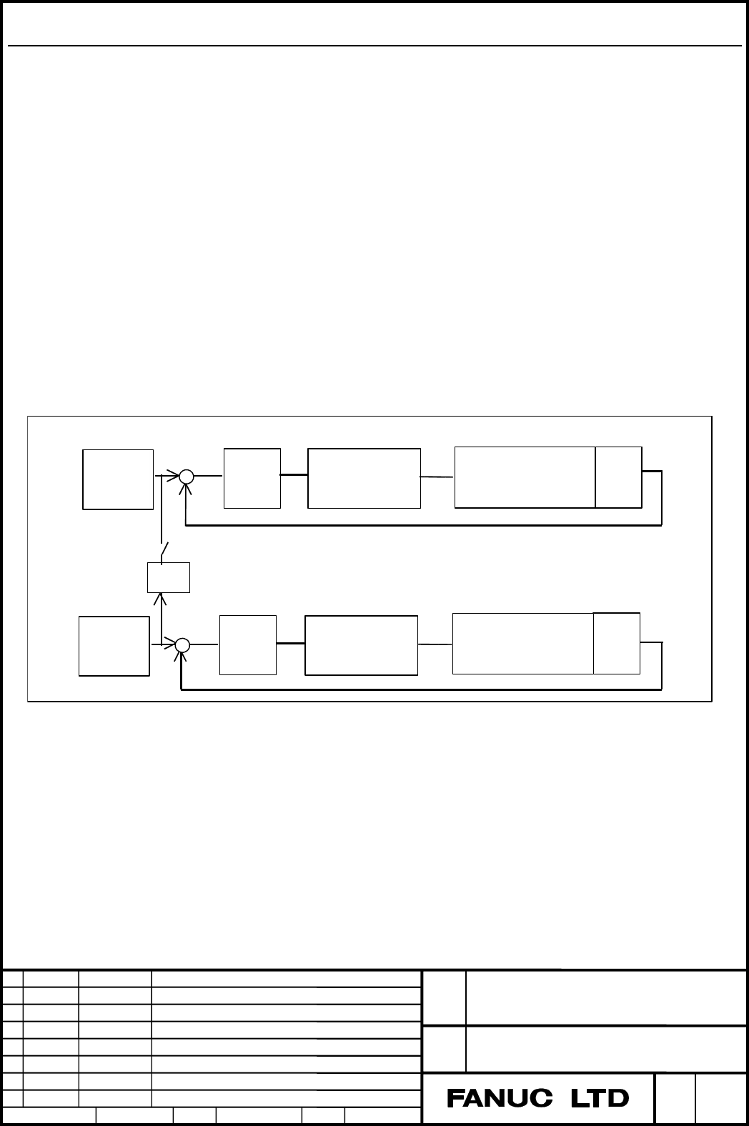
Block diagram
Slave axis
Synchronization switch
K : Synchronization coefficient
Master axis
Command
pulse
Position
control
Spindle amplifier
or servo amplifier
Spindle motor(Cs axis)
or servo motor
De-
tector
K
+
+
-
-
Command
pulse
Position
control
Spindle amplifier
or servo amplifier
Spindle motor(Cs axis)
or servo motor
De-
tector
Contents Summary of FANUC Series 30i/31i-MODEL A Flexible Synchronization Control Additional Manual
- Page 1FANUC Series 30i/31i-MODEL A Flexible synchronization control Specifications FANUC Series 30i/31i-MODEL A Title Flexible synchronization control Draw A-79620E No. Ed. Date Design Description page 1/13 Date Jul.16.’04 Design. Apprv.
- Page 2General This function is provided for machines that require synchronizing two or more different gear ratios, such as a hobbing machine. The function can simultaneously place up to four sets in synchronization independently. For example, it is possible to realize special hobbing machine functions, su
- Page 3Parameter setting The flexible synchronization control parameters are listed below: (1) Denominators determining gear ratios (parameter Nos. 5681, 5683, 5685, and 5687) (2) Numerators determining gear ratios (parameter Nos. 5680, 5682, 5684, and 5686) (3) Indexes to gear ratio denominators (paramete
- Page 4Program example Axis configuration of X, Y, Z, B (Cs axis), C, U, and V Group A: Master axis B, slave axis C, gear ratio of 1:50, M50 for turning on, M51 for turning off Group B: Master axis Z, slave axis C, gear ratio of 1:5, M52 for turning on, M53 for turning off Group C: Master axis Y, slave axi
- Page 55) Issuing G28, G30, G30.1 or G53 during synchronization control results in the PS010 (IMPROPER G CODE) alarm being issued. Before issuing G28, G30, G30.1 or G53, cancel synchronization control. 6) The parameters (Nos. 5660 to 5667, 5670 to 5677, 5680 to 5687, and 5690 to 5693) can be set in a part
- Page 614) A synchronous group which makes the PMC axis a master axis must turn on synchronous modes most first. Moreover, a synchronous group which makes the PMC axis a master axis must turn off the synchronous mode at the end. 15) When a synchronous group which makes the axis a master axis is used, a syn
- Page 7Parameter 5660 Master axis number (group A) 5661 Slave axis number (group A) 5662 Master axis number (group B) 5663 Slave axis number (group B) 5664 Master axis number (group C) 5665 Slave axis number (group C) 5666 Master axis number (group D) 5667 Slave axis number (group D) [Input type] Parameter
- Page 8Note) The machine coordinates update is not done though the slave axis operates on the motor. In this case, if an automatic reference position return to origin is done after the synchronous mode is canceled, the alarm of DS0405(ZERO RETURN END NOT ON REF) is issued. Please use a manual reference pos
- Page 95670 M code number for turning on the flexible synchronization control mode(group A) 5671 M code number for turning off the flexible synchronization control mode(group A) 5672 M code number for turning on the flexible synchronization control mode(group B) 5673 M code number for turning off the flexi
- Page 105680 Numerator determining gear ratio for flexible synchronization(group A) 5681 Denominator determining gear ratio for flexible synchronization(group A) 5682 Numerator determining gear ratio for flexible synchronization(group B) 5683 Denominator determining gear ratio for flexible synchronization(g
- Page 11Signal Flexible synchronization control mode select signals MTA,MTB,MTC,and MTD
- Page 12Alarms and messages No. Message Description PS5242 ILLEGAL AXIS NUMBER When the flexible synchronization mode is turned from off to on during an automatic operation, the specified master or slave axis number is incorrect. PS5243 DATA OUTRANGE When the flexible synchronization mode is turned from off
- Page 13No. Message Description PS5245 OTHER AXIS ARE ・Both the master axis and its slave COMMANDED axis, which is in synchronization with the master axis, happen to be the same Superimposed Control axis. ・Both the slave axis, which is in synchronization with the master axis, happen to be the same Synchrono