Additional Specification of Non-Waterproof Connector to Additional Manual Page 12
Additional Manual
DRAW.
N
o.
TITLE
Pa
g
e 11/13DESCRIPTIONDESIGN DATE
EDIT
01
NAGATOMO
New
αiBZ sensor
A-56731E-0100
FANUC LTD
05.11.02
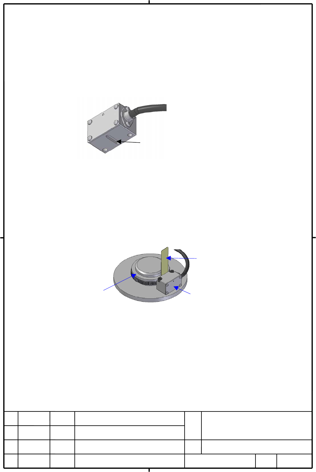
(7)-4 The installation of the sensor head
The installation method of αi BZ sensor is described below.
① Attach the sensor head to the sensor mounting surface so that the groove on the sensor
head is engaged with the parallel pins, and fix the sensor head temporally. Be careful
that the detection ring does not strike the sensor head in installing.
② Put the feeler gage (included: t=0.15mm) between the detection ring and the sensor
head. Push the sensor head to the detection ring lightly and fix the sensor head firmly
(recommended fastening torque: 1.3Nm +/- 10%). Use of some kind of thread locker is
recommended to prevent loosening of the screw to fix the sensor head.
③ Pull off the feeler gage. Rotate the spindle slowly and check that the detection ring does
not contact with the sensor head.
④ Confirm the gap between the sensor head and the detection ring is more than 0.1mm.
⑤ The α
i BZ sensor is so designed that the output voltage of the sensor is within the
permissible amount. But there is a possibility of that the voltage does not satisfies the
specification with the inappropriate installation.
Check that the output voltage satisfies the signal specification described in FANUC
BUILT-IN AC SPINDLE MOTOR αi series (B-65292EN), chapter II
The groove on the sensor head for the parallel pins to
be engaged
Fig.5
Sensor head
Detection ring
Feeler gage
Fig.6
Contents Summary of Additional Specification of Non-Waterproof Connector to Additional Manual
- Page 1TECHNICAL REPORT(MANUAL) NO.TMS 05/051E Date Nov. 10,2005 General Manager of Servo Laboratory αiBZ sensor (additional specification of non-waterproof connector) 1. Communicate this report to: ○ Your information only ○ GE Fanuc-N, GE Fanuc-E FANUC Robotics MILACRON ○ Machine tool builder ○ Sales agen
- Page 2Additional specification of non-waterproof connector to αiBZ sensor 1.Type of applied technical documents 名 称 αiBZ sensor (Addition of non-waterproof connector variation ) Spec. No./ A-56731E-0100/01 Ver. 2.Summary of change Group Name/Outline New・Add Applicable Correct・Del Date Basic Function Optio
- Page 33.Outline αiBZ sensor with non-waterproof connector is newly added. The projected area of non-waterproof connector is smaller than that of waterproof connector and the wiring through the narrower duct comes to be possible. Former specification Additional specification セ ン サ ヘ ッド Sensor head Sensor h
- Page 4αi BZ sensor (1) Names and Drawing Numbers Remarks Drawing No. Number of Maximum Detection ring Name Waterproof Non-waterproof teeth speed Inner Outer connector connector diameter diameter αiBZsensor 128 A860-2150-T201 A860-2155-T201 20,000min -1 128 φ40 φ52 αiBZsensor 128H A860-2150-T211 A860-2155-
- Page 5Note1: Please take care that the accuracy listed above is the typical amount and it is not guaranteed. Note2: The amount of the accuracy mentioned above does not include the influence of the error caused by the radial eccentricity in the installation of the detection ring. The error amount caused by
- Page 6(5) Outline Drawing
- Page 7
- Page 8NOTE ・ The maximum permissible temperature is 80deg. ・ The αi BZ sensor is precision device, so please be very careful in its handling. In particular, don’t apply shock or stress to the sensor head. ・ Attach and fix the sensor cable to the machine to prevent the direct tensile stress to the sensor h
- Page 9(6) Interference amount for Shrink Fitting The table below indicates the interference amount of shrink fitting for each specification to the rotational speed. Unit: µm Maximum speed T201 T211 T311 T401 T404 T411 T511 T611 -1 (min ) 3000 φ6~φ32 φ6~φ32 φ6~φ34 φ7~φ35 φ7~φ35 φ7~φ35 φ8~φ43 φ11~φ41 3500 ↓
- Page 10(7) Installation (7)-1 Abstruct αi BZ sensor should be installed in the following procedure. 1. Insert and attach the parallel pins to the sensor mounting surface of the spindle. 2. Attach the detection ring to the spindle shaft (or the sleeve) by shrink fitting. 3. Adjust the gap between the sensor
- Page 11(7)-2 Dimensions on the sensor mounting surface Machine the hole and the tap on the sensor mounting surface as shown in fig. 3. Insert the parallel pins in the 2-φ3H6 holes. Parallel pins are used as a guide in adjusting the gap between the sensor head and the detection ring explained as mentioned i
- Page 12(7)-4 The installation of the sensor head The installation method of αi BZ sensor is described below. ① Attach the sensor head to the sensor mounting surface so that the groove on the sensor head is engaged with the parallel pins, and fix the sensor head temporally. Be careful that the detection rin
- Page 13(8) Connection
- Page 14