Connection Manual FOR Relay module A Additional Manual Page 9
Additional Manual
EDIT DATE DESIG.
TITLE
DESCRIPTION
DRAW NO
A-80035E
SHEET
CUST
9
/
8
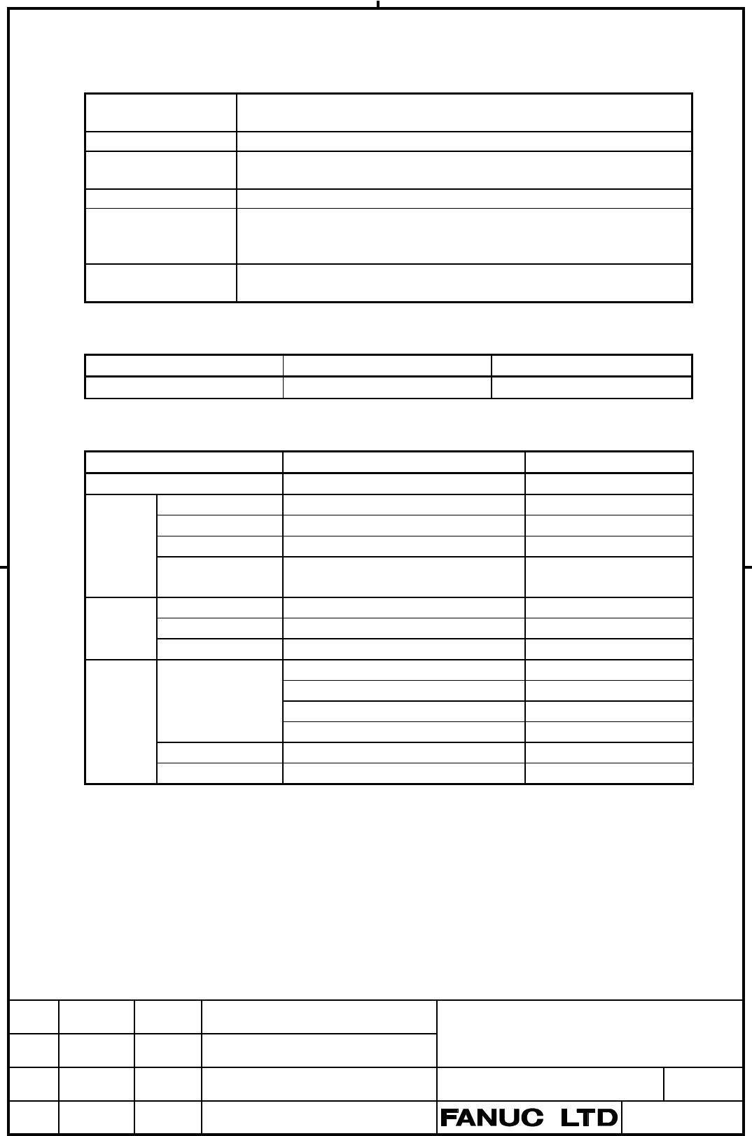
5. Specifications
5.1 Installation Specifications
Ambient Temperature At operation 0° to +55°C
Storing or transporting -20° to +60°C
Temperature Change Max. 1.1°C/min
Relative Humidity Normally 75% or less (Relative humidity)
Short time (Within one month) 95% or less (Relative humidity)
Vibration Operating 0.5G or less
Environment Normal FA atmosphere (The examination is necessary when using
the system under environments with higher degree of dust, coolant,
or organic solution.)
Other Requirements Use this module in a cabinet that is always completely closed.
5.2 Ordering Specifications
Item Specification Remarks
Relay Module A A20B-1006-0760 Length 100mm
5.3 Module Specifications
Item Specification Remarks
Output Points 10 points
Relay Coil resistance 1100Ω Rated voltage DC24V
coil On voltage Less than 70% of rated voltage
Off voltage More than 15% of rated voltage
Max. permissible
voltage
110% of rated voltage 23°C
Relay Number of contact 1a contact × 10
contact Rated load current AC250V 3A,DC30V 3A
Min. load current DC5V, 100mA
Terminal Connection wire Solid : 0.2 - 6.0mm
2
Stranded : 0 .2 - 4.0mm
2
AWG : AWG24-10
Stranded with ferrules : 0.5 - 4.0mm
2
without/with plastic collar
Stripping length 8mm
Tightening Torque 0.5 - 0.6Nm
Contents Summary of Connection Manual FOR Relay module A Additional Manual
- Page 1Relay Module A Connection Manual -Item- 1. Overview 2. Total Connection 3. Connection of Each Part 3.1 Terminal and Connector Pin Assignment of the Relay Module A. 3.2 Connection of the Relay module A 4. Outline of the Relay Module A 5. Specifications 5.1 Installation Specifications 5.2 Ordering Spe
- Page 21. Overview Relay Module A has 10 relays and is used when driving the load of the exceeding the rated current of the Connector Panel I/O Module’s DO. This module is connected to the Terminal module A “A03B-0815-C021” which the Connector Panel I/O Module is mounted on with a flat cable. And connect o
- Page 3. 3. Connection of Each Part 3.1 Pin Assignment Terminal and Connector pin assignment of the Relay Module A. XT1 XP1 XP2 1 KA1A A01 +24E B01 +24E A01 +24E B01 +24E 2 COM1 3 KA1C A02 B02 A02 B02 4 COM1 5 KA2A A03 B03 Yn+0.2 A03 B03 Yn+1.4 6 COM1 7 KA2C A04 Yn+0.6 B04 Yn+0.0 A04 Yn+1.6 B04 Yn+1.2 8 CO
- Page 43.2 Connection of the Relay Module A Connector Panel I/O Module Terminal Module A CB150 (01) XT150A DC24V Power source (33) +24E (17) V+ 0V DOCOM XT150A,XT150B 0V (1) (16) Relay Module A(#1) Address No. X150 XP1 Bit No. (A24)(B24) (A24)(B24) (A25) (A25) XT150B (20) (21) Yn+0.0 (34) (B04) (B05) KA1 D
- Page 5Note) At Connection parts of the Terminal Module A, means the terminal “XT150B”, means the connector “X150”. Connector Panel I/O Module Terminal Module A Relay Module A(#1) Relay module A(#2) 0V DOCOM(+24E) 0V +24E X150 XP1 XP2 XP1 (A01) (A01) (A01) (A01) (B01) (B01) (B01) (B01) XT1 (A24)(B24) (A24)
- Page 6Relay module A XT1 +24E KA1A (1) COM1 (2) KA1 KA1C (3) COM1 (4) KA2A (5) COM1 (6) KA2 KA2C (7) COM2 (8) COM2 (9) COM3 (10) KA3 KA3A (11) COM3 (12) KA34C (13) COM3 (14) KA4 KA4A (15) COM4 (16) KA5 KA5A (17) COM4 (18) KA56C (19) COM4 (20) KA6 KA6A (21) COM5 (22) COM5 (23) COM6 (24) KA7A (25) COM6 (26)
- Page 7TITLE DRAW NO CUST A-80035E SHEET EDIT DATE DESIG. DESCRIPTION 7/ 8�
- Page 84. Outline of the Relay Module A XP1 XP2 Threaded hole for earth (M4) XT1 Unit=mm TITLE DRAW NO CUST A-80035E SHEET EDIT DATE DESIG. DESCRIPTION 8/ 8�
- Page 95. Specifications 5.1 Installation Specifications Ambient Temperature At operation 0° to +55°C Storing or transporting -20° to +60°C Temperature Change Max. 1.1°C/min Relative Humidity Normally 75% or less (Relative humidity) Short time (Within one month) 95% or less (Relative humidity) Vibration Op