High Resolution Serial Output Circuit Additional Manual Page 10
Additional Manual
High Resolution Serial Output
Circuit
9 9
FANUC LTD
A-56731E-0079
DescriptionDesig.DateEdit.
01 97.01.30 MAEDA Taniguchi
title
Sheet
Draw. No.
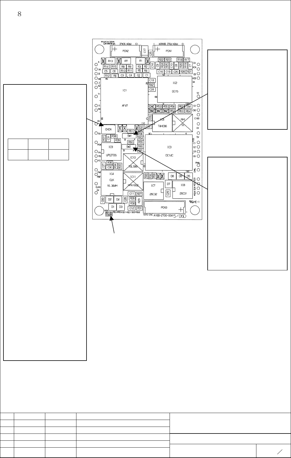
. SETTING PINS AND CHECK PINS
Check pins in “CHCN”
Signals of 90, 0, T1, 0V, 5V,
and PZ can be observed in this
check pins.
The location is shown below.
90 T1 5V
00VPZ
90:
Differentially amlified signal
from B and XB input signals.
0:
Differentially amplified signal
from A and XA input signals.
T1:
2.5V DC (=1/2 Vcc)
0V:
Signal ground
5V:
Power source
PZ:
Comparated digital signal
from Z and XZ input signals
.
Check pins “CHCN” is added
on PCB version 06D or later.
Location of check pins is displayed.
Setting pin “SW1”
“A” setting:
CMAL function, by checking
position data and reference
signal, is valid.
“B” setting
Above function is invalid.
Setting pin “SW2”
“A” setting:
For analog reference signal
input.
“B” setting
For digital reference signal
input.
Setting pin “SW2” is added
on PCB version 06D or later.
02 2001.5.24 Kikuchi This page added Taniguchi
Contents Summary of High Resolution Serial Output Circuit Additional Manual
- Page 1TECHNICAL REPORT (MANUAL) No. TMS01 / 018E Date June 08 , 2001 General Manager of Servo Laboratory High Resolution Serial Output Circuit 1. Distribute this report to the destinations marked with Your information GE Fanuc-N, GE Fanuc-E Fanuc Robotics-NA, Fanuc Robotics-E CINCINNATI MILACRON Machine t
- Page 2High Resolution Serial Output Circuit 1. Type of applied technical documents Name High Resolution Serial Output Circuit Spec. No. / Version A-56731E-0079 2. Summary of Change Group Name / Outline New, Add, Applicable Correct, Delete Data Basic Function Optional Setting pin “SW2” and check pin “CHCN”
- Page 3GENERAL In this manual, the specifications and the connection diagram of High Resolution Serial Output Circuit are described. BLOCK DIAGRAM High Resolution Serial Output Circuit 1 2 Encoder SPECIFICATION AND FUNCTION (1)Specification Ordering Number Current Consumption MAX. (2) Function High Resolut
- Page 4(4) Input specifications and examples of available linear encoders (4)-1 Input specifications A/B(type ) VB a/2 VXA,VXB TZ,LZ a VA a/2 c/2 Usable component VOA,VOB VOZ c/2 c 0V A/B type 0V VB VA b/2 b VXA b/2 VXB VOA,VOXA 0V VOB,VOXB Item Symbol Specification Specification Specification Unit Min. Ty
- Page 5(4)-2 Available Linear Encoders(Analog signal output type) Encoder Maker Encoder pitch of Maximum Scale Length Name sinful m) Velocity(m/min.) (mm) HEIDENHAIN LS486 20 120 70 2040 HEIDENHAIN LS186 20 120 240 3040 HEIDENHAIN LB381 100 120 440 30040 HEIDENHAIN LF481 4 48 50 1220 HEIDENHAIN LT181 20 12
- Page 6.CONNECTION DIAGRAM (1)Cable K High Resolution Serial Output Circuit SD1 (3) (As for the connection XSD1 (4) of the CNC side,refer the REQ (1) manual of of each CNC) XREQ (2) 0V (9),(10),(11) 5V (12),(13),(14) SHIELD (15) Connect to Earth Bar HIROSE RM21WTP-15S-(8) Recommended 5V,0V 0.5mm2 or more
- Page 7(2)Cable K High Resolution Serial output Encoder Circuit A (5) XA (6) B (7) XB (8) Z (9) XZ (10) 0V (3),(4) 5V (1),(2) SHIELD (11) HIROSE RM15WTP-12P-(dia) Use wire that is specified by the encoder maker. Designate “dia” [mm] of the connector, according to diameter of the cable that is used. (5 dia
- Page 8(3)Cable Length Design Design the length of cables as the sums of voltage drop by K1 and K2 becomes 0.2V or less. Note that voltage drop of K1 is caused by the total current consumption of High Resolution Serial Output Circuit and the encoder. Example of calculation Case that HEIDENHAIN LS486 is use
- Page 9. EXTERNAL DIMENSIONS TO:ENCODER FROM:CNC title High Resolution Serial Output Circuit Draw. No. A-56731E-0079 01 97.01.30 MAEDA Taniguchi Sheet Edit. Date Desig. Description FANUC LTD 8 9
- Page 10. SETTING PINS AND CHECK PINS Setting pin “SW1” “A” setting: CMAL function, by checking position data and reference Check pins in “CHCN” signal, is valid. Signals of 90, 0, T1, 0V, 5V, “B” setting and PZ can be observed in this Above function is invalid. check pins. The location is shown below. 90 T