FANUC SERVO AMPLIFIER Beta i series DESCRIPTION Additional Manual Page 16
Additional Manual
TITLE
DRAW
.
No.
15/37
Page
FANUC LTD
DESCRIPTION DESIGN DATE
EDIT
FANUC SERVO AMPLIFIER
βi series SVM DESCRIPTIONS
A
-72562EN-026
6. Setting switch for DC alarm level
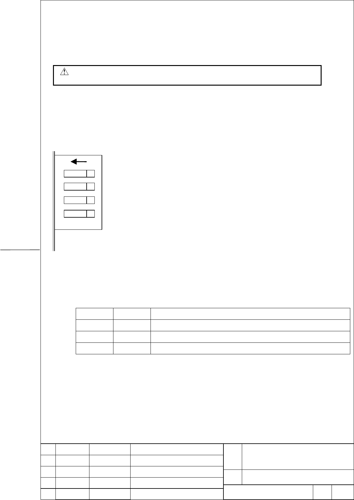
With SVM1-40 and SVM1-80, four switches are provided on the front of the servo amplifier. Be
sure to set the switches to match the resistor used.
WARNING
If the switches are set incorrectly, the regenerative resistor may be damaged.
From top to bottom, switch 1, switch 2, switch 3, and switch 4 are installed in this order. Each
switch is turned on when the lever is at the left, and is turned off when the lever is at the right.
ON
12
34
(1) Setting of switch 3 and switch 4
The switches need to be set according to the regenerative discharge resistor used.
⇒ If the switches are not set correctly, the regenerative overheat alarm is not detected
correctly.
Switch 3 Switch 4 Regenerative discharge resistor
ON ON Built-in
OFF ON Separate : A06B-6089-H500
OFF OFF Separate : A06B-6089-H713, A06B-6089-H714
(2) Setting of switch 1 and switch 2
Switch 1 and switch 2 are not used. Set these switches off.
Contents Summary of FANUC SERVO AMPLIFIER Beta i series DESCRIPTION Additional Manual
- Page 1TECHNICAL REPORT (MANUAL) NO. TMS03/010E Date: 2003/03/31 General Manager of Servo Laboratory FANUC SERVO AMPLIFIER βi series DESCRIPTIONS 1. Communicate this report to: Your information only GE Fanuc-N, GE Fanuc-E FANUC Robotics MILACRON Machine tool builder Sales agency End user SLB4S1 2. Summary
- Page 21. Configuration SVM1-4, SVM1-20 Fan unit βi βi SVM1-20 SVM1-4 FUSE FUSE Stabilized power supply +24V etc CXA19B CXA19A CXA19B CXA19A DC24V Optical cable NC 3 phase COP10B COP10A COP10B COP10A AC200V - 240V Optical cable AC Line Breaker MCC filter CZ7 CZ7 Control signal of 5A MCC breaker CX29 JX5 CX
- Page 3SVM1-40, SVM1-80 βi βi SVM1-80 SVM1-40 FUSE FUSE +24V etc Stabilized power supply CXA19B CXA19A CXA19B CXA19A DC24V NC Optical cable 3 phase COP10B COP10A COP10B COP10A Optical cable AC200V –240V AC line Breaker MCC CZ4 CZ4 filter Control signal for MCC 5A CX29 CX29 Breaker ESP JX5 ESP signal CX30 C
- Page 42. Specification (1) SVM1-4, SVM1-20 Item Specification Power supply voltage (power) 3 phase AC200V - 240V 1 phase AC220V - 240V Power supply voltage (control) DC24V / 0.9A Dynamic brake Built in (2) SVM1-40, SVM1-80 Item Specification Power supply voltage (power) 3 phase AC200V-240V Power supply vo
- Page 53. Order number Refer to order list (B-65321EN). FANUC SERVO AMPLIFIER TITLE βi series SVM DESCRIPTIONS DRAW. No. A-72562EN-026 EDIT DATE DESIGN DESCRIPTION FANUC LTD Page 4/37
- Page 64. Outer diagram/ Panel cut diagram/ Maintenance area diagram 4.1 Outer diagram (1) SVM1-4, SVM1-20 FANUC SERVO AMPLIFIER TITLE βi series SVM DESCRIPTIONS DRAW. No. A-72562EN-026 EDIT DATE DESIGN DESCRIPTION FANUC LTD Page 5/37
- Page 7(2) SVM1-40, SVM1-80 FANUC SERVO AMPLIFIER TITLE βi series SVM DESCRIPTIONS DRAW. No. A-72562EN-026 EDIT DATE DESIGN DESCRIPTION FANUC LTD Page 6/37
- Page 8(3) Fan unit (A06B-6134-K002) FANUC SERVO AMPLIFIER TITLE βi series SVM DESCRIPTIONS DRAW. No. A-72562EN-026 EDIT DATE DESIGN DESCRIPTION FANUC LTD Page 7/37
- Page 9(4) Fan unit (A06B-6134-K003) 6.5 62 60 17.5 max. 60 60 Yamanashi 401-0 597 JAPAN made in JAPAN 75 FANUC SERVO AMPLIFIER TITLE βi series SVM DESCRIPTIONS DRAW. No. A-72562EN-026 EDIT DATE DESIGN DESCRIPTION FANUC LTD Page 8/37
- Page 104.2 Panel cut diagram SVM1-40, SVM1-80 Note Attach packing to prevent the ingress of oil and dust. Reinforce the right and left ends of each panel cutout in the power magnetic cabinets, for example, with L-angle steel, to ensure reliable contact with the amplifier modules. FANUC SERVO AMPLIFIER TITL
- Page 11Maintenance area diagram (1) SVM1-4, SVM1-20 FANUC SERVO AMPLIFIER TITLE βi series SVM DESCRIPTIONS DRAW. No. A-72562EN-026 EDIT DATE DESIGN DESCRIPTION FANUC LTD Page 10/37
- Page 12(2) SVM1-40, SVM1-80 (a) Without AC fan motor (A06B-6134-K002) FANUC SERVO AMPLIFIER TITLE βi series SVM DESCRIPTIONS DRAW. No. A-72562EN-026 EDIT DATE DESIGN DESCRIPTION FANUC LTD Page 11/37
- Page 13(b) With AC fan motor (A06B-6134-K002) FANUC SERVO AMPLIFIER TITLE βi series SVM DESCRIPTIONS DRAW. No. A-72562EN-026 EDIT DATE DESIGN DESCRIPTION FANUC LTD Page 12/37
- Page 145. Connector location (1) SVM1-4, SVM1-20 Names Note 1 DC link charge LED 2 CZ7-1 Input power ① 3 CZ7-2 Discharge resistor 4 CZ7-3 Motor power ⑧ ⑨ 5 CX29 Control signal for MCC 6 CX30 ESP signal Yamanashi 401-0597 JAPAN made in JAPAN ⑩ 7 CXA20 Discharge resistor (alarm signal) ② 8 CXA19B DC24V power
- Page 15(2) SVM1-40, SVM1-80 Names Note 1 DC link charge LED 2 CX29 Control signal for MCC 3 CX30 ESP signal 4 CXA20 Discharge resistor (alarm signal) Yamanashi 401-0597 JAPAN 5 SW Setting switch ① ⑨ (DC alarm level) ② ⑩ 6 CZ4 Input power ③ 7 CZ5 Motor power ④ ⑪ 8 CZ6 Discharge resistor ⑫ 9 CXA19B DC24V pow
- Page 166. Setting switch for DC alarm level With SVM1-40 and SVM1-80, four switches are provided on the front of the servo amplifier. Be sure to set the switches to match the resistor used. WARNING If the switches are set incorrectly, the regenerative resistor may be damaged. From top to bottom, switch 1,
- Page 177. Cable Connect diagram 4A, 20A type Fan unit βi SVM βi SVM 20A 4A FUSE FUSE Stabilized power supply K6 K6 CXA19B CXA19A CXA19B CXA19A DC24V NC Optical cable COP10B COP10A COP10A COP10B 3 phase Optical cable AC200V – 240V Breaker MCC ACライン K2 K2 CZ7 CZ7 フィルタ K4 5A K7 breaker CX29 JX5 CX29 JX5 ESP K
- Page 1840A, 80Atype βiSVM βiSVM 80A 40A FUSE FUSE Stabilized power supply K6 K6 DC24V CXA19B CXA19A CXA19B CXA19A NC Optical cable COP10B COP10A COP10A 1 phase COP10B Optical cable AC200V - 240V AC Breaker MCC line CZ4 CZ4 filter K2 K2 K7 5A CX29 CX29 ESP breaker K8 JX5 JX5 Switch CX30 CX30 K5 CXA20 JF1 K5
- Page 19Detail of K1 αi, αis series servo motor βis series servo motor(β0.4/5000is ..β22/2000is) shield SVM Servo Motor (5) RD (6) (6) *RD (5) (9, 20) 5V (8, 9) (12, 14) 0V (7, 10) (7) 6V (4) (16) drain wire FG (3) 20-pin half-pitch connector Connector (Japan Aviation Electronics Industry) JN2□S10SL1 : for
- Page 20Note2 1. In case that the cable is prepared by MTB, total resistance of 5V and 0V must be less 2 ohm. 2. Pulsecoder side connector can accept maximum 0.5mm2 (wire construction 20/0.18 or 104/0.08, diameter φ1.5 or less) wire and sheath diameter is φ5.7 to φ8.0. In case of using thicker wire or cable
- Page 21βis series servo motor (β0.2/5000is, β0.3/5000is) shield SVM servo motor (1) SD (A4) (2) *SD (B4) (5) REQ (A3) (6) *REQ (B3) (9, 20) 5V (A2, B2) (12, 14) 0V (A1, B1) (7) 6V (A5) (16) drain wire FG (B6) 20-pin half-pitch connector Housing: : 1-1318118-6(D-2100D 12P) Contact : 1318107-1(D-2 REC M) ear
- Page 22Note 2 In case that the cable is prepared by MTB, total resistance of 5V and 0V must be less 0.8 ohm. Pulsecoder side connector can accept 0.5mm2 (crimp tool 1463475-1 is used) wire and sheath is 0.85mm2. (crimp tool 1276654-1 is used) In case of using thicker wire or cable, take measures described
- Page 23Detail of K2 Refer to described below. (1) Connector (2) Cable selection (3) Input power cable (1) Connector (a) SVM1-4, SVM1-20 βiSVM CZ7 (B1) L1 CZ7 (A1) L2 CZ7 (B2) L3 CZ7 (A2) FANUC SERVO AMPLIFIER TITLE βi series SVM DESCRIPTIONS DRAW. No. A-72562EN-026 EDIT DATE DESIGN DESCRIPTION FANUC LTD Pa
- Page 24[Hausing] Use following hausing. Type Key Maker 175363-3 Key type Tyco Electronics AMP [Contact] Use following contact. Wire size Wire size Insulation outer Tool type Type Maker (mm2) AWG diameter (mm) L size 1-175218-2 0.5- 1.25 20/18/16 1.8-2.8 91558-1 Tyco Electronics AMP [FANUC order number of c
- Page 25(b) SVM1-40, SVM1-80 βiSVM CZ4 (B1) L1 CZ4 (A1) L2 CZ4 (B2) L3 CZ4 (A2) [Hausing] Use following hausing. Type Key Maker 1-917807-2 XX Tyco Electronics AMP [Contact] Use following contact. Wire size Wire size Insulation Tool type Type outer diameter Maker (mm2) AWG (mm) S size 316040-6 1.25 – 2.20 16
- Page 26[Crimping tool] Order number Content Tool: 234170-1 A06B-6110-K220#D5S Contact: S size 316040-6 Appliable wire width: 1.25-2.2mm2, AWG16/14 Tool: 234171-1 A06B-6110-K220#D5M Contact: M size 316041-6 Appliable wire width: 3.50-5.50mm2, AWG12/10 A06B-6110-K220#D5R Release tool: 409158-1 FANUC SERVO AM
- Page 27(2) Cable selection Select cable as follows. ① Motor rated current or more ② Cable type (Maximum operating temperature etc.) ③ Environment temerature ⑤ Necessary fo CE marking (several safety certification or EMC certification) An example of cable selection is described below. If you refer follows,
- Page 28(3) Input power cable Input cable width is described bellow. 【Maximum input current of amplifier in case of driving follows.(Reference)】 At 3 φ input At 1φ input Rated Rated (Example 1.) (Example 2.) Motor current current Wire width Wire width [Arms] [Arms] [mm2] [mm2] (Reference) (Reference) β0.2/5
- Page 29Detail of K3 Refer to described below. (1) Connector (2) Cable selection (3) Output power cable (1) Connector (a) SVM1-4, SVM1-20 βi SVM Motor CZ7 (B1) U U CZ7 (A1) V V CZ7 (B2) W W CZ7 (A2) GND(Body) [Hausing] Use following hausing. Type Maker 1318095-2 Tyco Electronics AMP [Contact] Use following
- Page 30(b) SVM1-40, SVM1-80 βiSVM Motor CZ5 (B1) U U CZ5 (A1) V V CZ5 (B2) W W CZ5 (A2) GND(Body) [Hausing] Use following hausing. Type Key Maker 2-917807-2 YY Tyco Electronics AMP [Contact] Use following contact. Insulation Tool type Wire size Wire size Type outer diameter Maker (mm2) AWG (mm) S size 3160
- Page 31(2) Cable selection Refer to section “Detail of K2”. (3) Output power cable (a) Output cable (b) Connector of motor (a) Output cable Output cable width is described bellow. 【Maximum output current of amplifier. (Reference)】 Rated current (Example 1.) (Example 2.) Motor [Arms] Wire width Wire width (
- Page 32Detail of K4, K5 (1) SVM1-4, SVM1-20 (a) With discharge resistor A06B-6130-H401 Below hausing and contact are connected. A06B-6130-H402 Below hausing and contact are added. βiSVM Discharge resistor CZ7(DCP) B1 DCP CZ7(DCC) A1 DCC Hausing: 175362-3 Contact: 1-175218-2 Maker: Tyco electronics AMP Wire
- Page 33(b) Without discharge resistor βiSVM Open CZ7(DCP) B1 CZ7(DCC) A1 Short CXA20-1 (TH1) CXA20-2 (TH2) Hausing: 1-1318120-3 Contact: 1318107-1 Maker: Tyco electronics AMP Wire width: 0.30 – 0.85mm2 WARNING Do not connect DCP terminal to DCC terminalwith short-wire. We recommend to protect correct inser
- Page 34(2) SVM1-40, SVM1-80 (a) With separated discharge resistor βiSVM Discharge resistor CZ6-B1 (RC) CZ6-B2 (RE) Cable specification:Vinyle cabtyre cable JIS C 3312 2-core Conduct 3.5mm2 Crimp terminal: 5.5-4 Hausing: 3-917807-2 Contact: 316041-6 Appliable wire width 3.5mm2 - 5.5mm2 Maker:Tyco electronic
- Page 35(b) With built-in discharge resistor βiSVM Short CZ6-A1 (RC) CZ6-A2 (RI) Cable specification: Vinyle cabtyre cable JIS C 3312 2-core Conduct 3.5mm2 Crimp terminal: 5.5-4 Hausing: 3-917807-2 Contact: 316041-6 Appliable wire width: 3.5mm2 - 5.5mm2 Maker: Tyco electronics AMP CXA20-1 (TH1) Short CXA20-
- Page 36Detail of K6 βiSVM βiSVM CXA19B-A1 (24V) CXA19A –A1 (24V) CXA19B-B1 (24V) CXA19A-B1 (24V) CXA19B-A2 (0V) CXA19A –A2 (0V) CXA19B-B2 (0V) CXA19A-B2 (0V) CXA19B-A3 (ESP) CXA19A –A3 (ESP) CXA19B-B3 (BAT) CXA19A-B3 (BAT) Hausing: 1-1318119-3 Hausing: 1-1318119-3 Contact: 1318107-1 Contact: 1318107-1 Appl
- Page 37Detail of K7 βiSVM CX29-1 (RLY1) CX29-3 (RLY2) Hausing: 3-1318120-3 Contact: 1318107-1 Appliable wire width: 0.3mm2 - 0.85mm2 Maker: Tyco electronics AMP Detail of K8 βiSVM CX30-1 (24V) CX30-3 (ESP) Housing: 2-1318120-3 Contact: 1318107-1 Applicable wire width: 0.3mm2 - 0.85mm2 Maker: Tyco electroni
- Page 38Detail of K9 βiSVM Battery case CXA19B-A1 (24V) CXA19B-B1 (24V) CXA19B-A2 (0V) 0V CXA19B-B2 (0V) CXA19B-A3 (ESP) CXA19B-B3 (BAT) 6V Hausing: 1-1318119-3 Crimp terminal: 1.25-2 Contact: 1318107-1 Appliable wire width: 0.3mm2 - 0.85mm2 Appliable wire width: 0.3mm2 - 0.85mm2 Maker: Tyco electronics AMP