Series 30i-Model A, Live Tool Control with Servo Motor Additional Manual Page 11
Additional Manual
A-79595E
Title
Draw
No.
Ed. Date Design Description
Date May.24.’04 esig. Apprv.
11/33
Sheet
FANUC Series 30i-MODEL A
Live Tool Control With Servo Motor
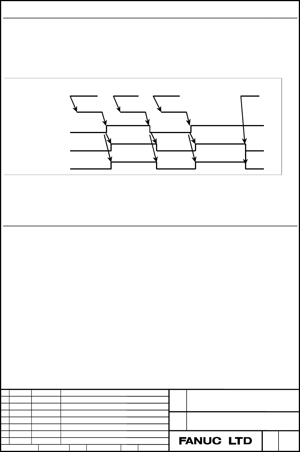
Spindle stop signal *SSTP<Gn029#6>
[Classification] Input signal
[Function] The command output to the spindle is disabled.
[Operation] When the spindle stop signal turns to "0" , the output voltage becomes 0V
and the enable signal ENB turns to "0" (M05 is not output).
When this signal turns to "1", the analog voltage returns to its original value
and the ENB signal turns to "1".
Input command
S
××××
M03
M05 M04 S0
Miscellaneous function
processing
Spindle stop signal
Enable signal
Command output to
the spindle 0
“0"
“1"
The above time chart is an example. Actually, the time chart should meet the
specification of the spindle control unit.
- When this signal is not used, always set the signal to "1".
-When the M03, M04, or M05 command is issued, the CNC outputs
the code signal and strobe signal only.
Individual spindle stop signals *SSTP1<Gn027#3> *SSTP2<Gn027#4> *SSTP3<Gn027#5>
*SSTP4<Gn026#6>
[Classification] Input signal
[Function] Effective only to multi-spindle, each spindle can be stopped by this signal.
*SSTP1 1: Does not set 0 min
-1
for output to the first spindle.
0: Sets 0 min
-1
for output to the first spindle.
*SSTP2 1: Does not set 0 min
-1
for output to the second spindle.
0: Sets 0 min
-1
for output to the second spindle.
*SSTP3 1: Does not set 0 min
-1
for output to the third spindle
0: Sets 0 min
-1
for output to the third spindle.
*SSTP4 1: Does not set 0 min
-1
for output to the fourth spindle.
0: Sets 0 min
-1
for output to the fourth spindle.
Contents Summary of Series 30i-Model A, Live Tool Control with Servo Motor Additional Manual
- Page 1FANUC Series 30i-MODEL A Live Tool Control With Servo Motor Specifications Contents 1. Overview ・・・・・・・・・・・・・・・・・・・・・・・・・・・・・・・・・・・・・・・・・・・・・・・・・・・・ 2 2. Spindle speed control with servo motor ・・・・・・・・・・・・・・・・・・・・・・・・・ 4 3. Live tool indexing function ・・・・・・・・・・・・・・・・・・・・・・・・・・・・・・・・・・・ 29 4. Rigid
- Page 21. Overview This function allows you to execute spindle rotation commands and spindle-speed functions such as rigid tapping, with a servo motor. -Spindle speed control with servo motor Allows you to perform speed control with rotation commands (S commands), using a servo motor as a live tool. At the
- Page 3The relationship between the spindles and functions Spindle Spindle Speed Live Tool Control Function Control With Servo Motor Threading/feed per revolution ○ × Polygon turning ○ ×*1 Spindle speed fluctuation detection ○ × Spindle synchronous control ○ × Simple spindle synchronous control ○ × Polygon
- Page 42. Spindle speed control with servo motor Format G96.4 P_ ; SV speed control mode ON M03 (M04) S_ P_ ; Rotation command S: Spindle speed [min-1] (numeric value of up to five digits) P: Spindle selection with multi-spindle control You can turn SV speed control mode ON for each axis, using G96.4 and a
- Page 5(2) Conditions under which spindle speed command output is stopped The output of a command once output to the spindle becomes 0 if a command is specified which causes the spindle speed command output to become 0, such as *SSTP of "0" and a S0 command. Spindle speed command output also becomes 0 if l
- Page 6Mode switching with a signal Program Speed control mode ON/OFF Operation command ON (SV speed control mode in-progress M15 ; SV speed control mode ON (C) with an M code signal (C)=1) ON (SV speed control mode in-progress CW rotation about servo motor rotation axis C M03 S100 P1 ; signal (C)=1) at 10
- Page 7-Acceleration/deceleration(Time constant) You can switch the acceleration/deceleration during a rotation command in accordance with the speed. There are two switching points; you can specify parameters S0 and S1 (switching speed). Set the acceleration/deceleration in each of the three sections, usin
- Page 8-Setting of a rotation axis with a servo motor 1. Axis setting For the servo axis number of the axis to be set as a rotation axis with a servo motor (parameter No. 1023), set a value as a servo motor as usual. Specify which servo motor to use as the live tool axis, with SRV, bit 7 of parameter No. 1
- Page 9・Examples of parameter setting The following descriptions exemplify typical parameter setting for live tool control with servo motor using a serial pulse coder (with a million pulse capability). Without the explanation specify typical values in the parameter. (1) Live tool axis setting This example
- Page 10(2) Servo parameter setting Set the servo parameters as listed below: CMR=1, DMR=36/100 (With the above setting, the reference counter capacity is 360000.) No. 1820 (C)=2 (CMR) No. 1821 (C)=360000 (reference counter capacity) No. 2084 (C)=36 (DMR numerator) No. 2085 (C)=100 (DMR denominator) If the
- Page 11Spindle stop signal *SSTP
- Page 12Spindle speed overridesignals SOV0 to SOV7
[Classification] Input signal [Function] The spindle speed override signal specifies an override from 0% to 254% in 1% units for the S command sent to the CNC. [Operation] An override value in binary must be set in 8 bits from SOV7 to SOV0. The spind - Page 13Address P signals MSP00 to MSP15
- Page 14Alarm and message Number Message Description PS445 ILLEGAL AXIS OPERATION A positioning command is issued in speed control mode. Check the SV speed control mode in-progress signal. PS446 ILLEGAL COMMAND G96.1, G96.2, G96.3 and G96.4 were specified in the same IN G96.1/G96.2/G96.3/G96.4 block for oth
- Page 15Parameter #7 #6 #5 #4 #3 #2 #1 #0 1006 ROSx ROTx [Input type] Parameter input [Data type] Bit axis NOTE When this parameter is set, the power must be turned off before operation is continued. ROTx, ROSx Setting linear or rotation axis. ROSx ROTx Meaning 0 0 Linear axis ①Inch/metric conversion is don
- Page 161022 SEtting of each axis in the basic coordinate system [Input type] Parameter input [Data type] Byte axis [Valid data range] 0 to 7 To detrmine a plne for circular interpolation, cutter compensation, and so forth (G17: Xp-Yp plane, G18: Zp-Xp plane, G19: Yp-Zp plane) and a three-dimensional tool c
- Page 171260 Amount of a shift per one rotation of a rotary axis NOTE When this parameter is set, the power must be turned off before operation is continued. [Input type] Parameter input [Data type] Real axis [Unit of data] degree [Minimum unit of data] Depend on the increment system of the applied axis [Va
- Page 181820 Command multiplier for each axis (CMR) NOTE When this parameter is set, the power must be turned off before operation is continued. [Input type] Parameter input [Data type] Byte axis [Valid data range] See below. Set a command multiplier indicating the ratio of the least command increment to th
- Page 19Least command Least input increment increment IS-D Millimeter 0.00001mm (diameter specification) 0.000005mm Millimeter input 0.00001mm (radius specification) 0.00001mm machine 0.000001inch (diameter specification) 0.000005mm Inch input 0.000001inch (radius specification) 0.00001mm Millimeter 0.00001
- Page 20[Least command increment]: Minimum unit of commands issued from the CNC to the machine [Detection unit]: Minimum unit for machine position detection The unit of feedback pulses varies, depending on the type of detector. [Feedback pulse unit] = [Amount of travel per rotation of the pulse coder] / [Nu
- Page 211825 Servo loop gain for each axis [Input type] Parameter input [Data type] Integeraxis [Unit of data] 0.01/sec [Valid data range] 1 to 9999 Set the loop gain for position control for each axis. When the machine performs linear and circular interpolation (cutting), the same value must be set for all
- Page 22NOTE When safety monitoring using the dual check safety function is in progress (when the safety monitor signal SEV/SEP is set to 1), set a positioning deviation limit during travel in parameter No. 1838. 1829 Positioning deviation limit for each axis in the stopped state [Input type] Parameter inpu
- Page 23#7 #6 #5 #4 #3 #2 #1 #0 3703 MPP MPM 2P2 [Input type] Parameter input [Data type] Bit NOTE When this parameter is set, the power must be turned off before operation is continued. #0 2P2 When a multi-path system is used, inter-path spindle control allows: 0: Configuration where the spindle that belon
- Page 243717 Motor number to each spindle NOTE When this parameter is set, the power must be turned off before operation is continued. [Input type] Parameter input [Data type] Byte spindle [Valid data range] 0 to Maximum number of controlled axes Set a spindle amplifier number to be assigned to each spindle
- Page 25Spindle motor speed Max. speed (4095, 10V) Spindle motor max. clamp speed (Parameter No.3736) Spindle motor minimum clamp speed (Parameter No.3735) Spindle speed command (S command) Gear 1 Gear 2 Gear 3 Max. speed Max. speed Max. speed (Parameter (Parameter (Parameter No.3741) No.3742) No.3743) 3775
- Page 26NOTE 1. This parameter is valid if bit 3 (MPP) of parameterNo.3703 is set to 1. 2. If this parameter is set to 0, the corresonding spindle cannot be selected by a P code. 3. Under multipath control, the P code specified here is valid for each path. For instance, if the P code to select the first spi
- Page 27#7 #6 #5 #4 #3 #2 #1 #0 11000 SRV NOTE When this parameter is set, the power must be turned off before operation is continued. [Input type] Parameter input [Data type] Bit axis #7 SRV Live tool control with servo motor is 0: No used. 1: Used. 11010 Spindle number used by live tool control function N
- Page 2811015 Maximum motor speed [Input type] Parameter input [Data type] 2-word axis [Unit of data] min-1 [Valid data range] 0 to 99999999 An actual maximum speed of the motor becomes a speed that the feeding gear is effective in parameter No.11015. 11020 Acceleration/deceleration switching speed (S0) for
- Page 293. Live tool indexing function Format G96.1 P_ R_ ; Waits for the completion of live tool indexing and starts the operation of the next block after the completion G96.2 P_ R_ ; Starts the operation of the next block without waiting for the completion of live tool indexing G96.3 P_ ; Starts the opera
- Page 30・SV speed control mode cancellation If you perform live tool indexing with G96.1, SV speed control mode is canceled when live tool indexing is completed. If you perform live tool indexing with G96.2, use G96.3 to check for the completion of live tool indexing; it cancels SV speed control mode if it
- Page 31Signal Live tool indexing signal for each axis SPP1~SPP8
[Classification]Output signal [Function] This signal reports that live tool indexing is being executed on each axis. [Output condition]This signal becomes "1" if: ・Live tool indexing is not completed. It becomes "0" if: ・Live tool index - Page 324. Rigid tapping with servo motor Format The rigid tapping command format is the same as that of conventional rigid tapping. For details, see the explanation of conventional "Rigid tapping." NOTE Before executing the rigid tapping command, the servo motor as a rotation axis must be placed in positio
- Page 33Acceleration/deceleration control Acceleration/deceleration after interpolation Unlike conventional rigid tapping, rigid tapping with servo motor enables the application of bell-shaped acceleration/deceleration or linear acceleration/deceleration of constant acceleration/deceleration time type. When
- Page 34Acceleration/deceleration before interpolation In this rigid tapping, if AI contour control I or AI contour control II is available, by specifying rigid tapping in "acceleration/deceleration before look ahead interpretation" mode, you can perform acceleration/deceleration before look ahead interpola
- Page 35Parameter 1430 Maximum cutting feedrate for each axis [Input type] Parameter input [Data type] Real axis [Unit of data] mm/min, inch/min, degree/min (machine unit) [Minimum unit of data] Depend on the increment system of the applied axis [Valid data range] Refer to the standard parameter setting tab
- Page 36Maximum allowable acceleration rate in acceleration/deceleration before 11050 interpolation for each axis in rigid tapping [Input type] Parameter input [Data type] Real axis [Unit of data] mm/sec/sec, inch/sec/sec, degree/sec/sec (machine unit) [Minimum unit of data] Depend on the increment system o
- Page 37Time constant for acceleration/deceleration after cutting feed interpolation in 11052 the acceleration/deceleration before interpolation mode in rigid tapping [Input type] Parameter input [Data type] Word axis [Unit of data] msec [Valid data range] 0 to 4000 In the acceleration/deceleration before i
- Page 38Time constant for acceleration/deceleration deceleration after cutting feed 11065 interpolation in rigid tapping extraction (first gear) Time constant for acceleration/deceleration deceleration after cutting feed 11066 interpolation in rigid tapping extraction (second gear) Time constant for acceler