FANUC Series 30i/31i/32i -MODEL A DYNAMIC GRAPHIC DISPLAY FUNCTION Additional Manual Page 6
Additional Manual
Edit
Apprv.Desig.
Date
Design
Date
FANUC Series 30
i
/31
i
/32
i
–MODEL A
DYNAMIC GRAPHIC DISPLAY FUNCTION
(
Path Drawing
)
A
-90452E
Feb.20.2006
6/22
New design
Feb.20.2006
01
Page
Title
Draw
No.
Descri
p
tion
Explanation
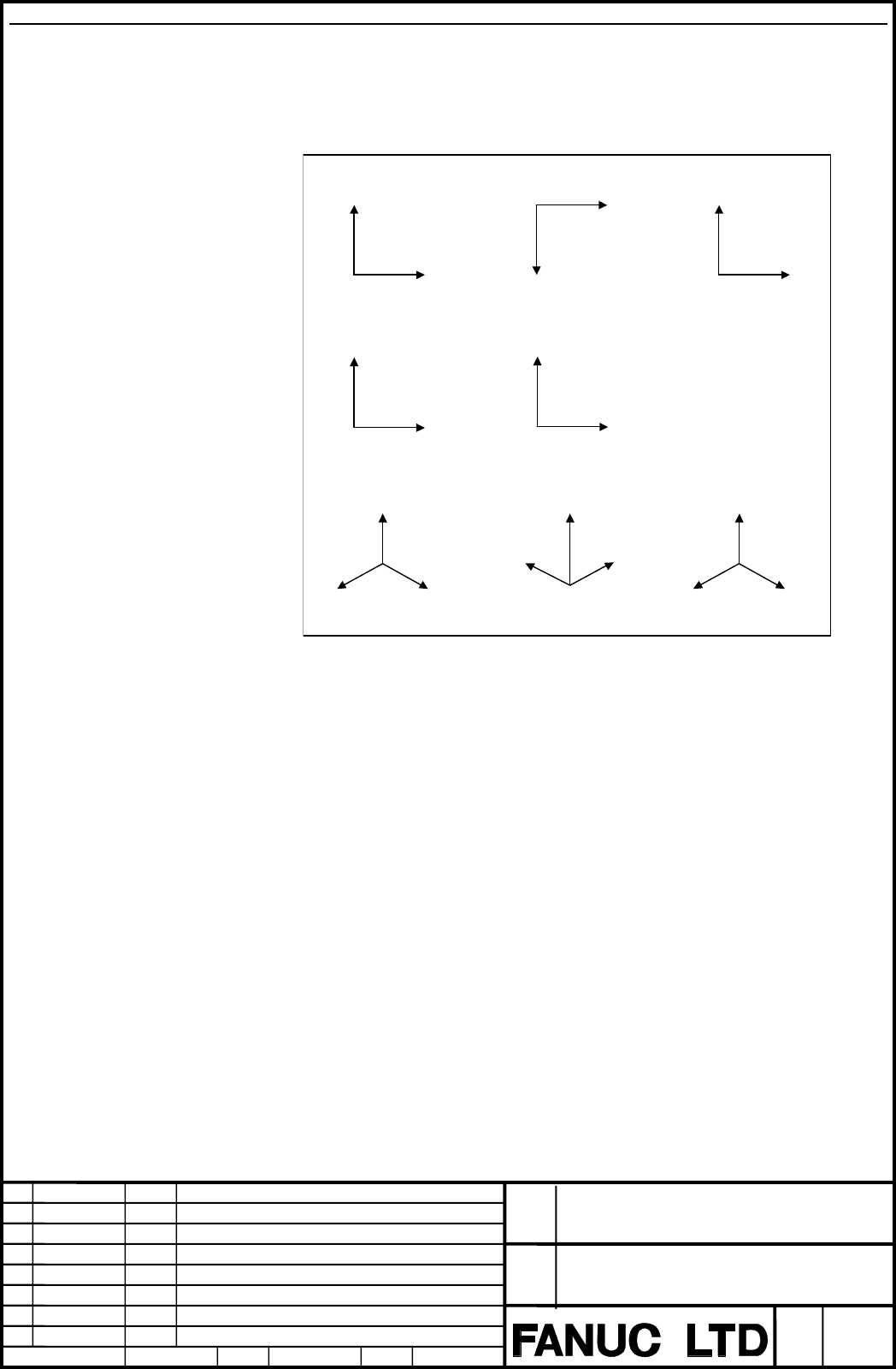
The setting items on the GRAPHIC PARAMETER screen are described below.
・Graphic coordinate system
Select a graphic coordinate system for drawing from the following and set its number.
Y
X
Setting=0 (XY)
Z
Y
Setting=1 (ZY)
Z
Y
Setting=2 (YZ)
Z
X
Setting =3 (XZ)
Setting=5 (XYZ)
Z
XY
Setting=6 (YXZ)
Z
Y
X
X
Z
Setting=4 (ZX)
Setting=7 (YZX)
X
Y Z
Fig. 1.1.1.1 (c) Graphic coordinate system
・Scale
Set a graphic scale in the range 0.01 to 100.00.
With a small scale factor, it is possible to draw within a wide range.
With a large scale factor, it is possible to draw in the vicinity of the graphic center being
enlarged.
・Graphic range center
To specify the center coordinates of a graphic range, set a coordinate on each axis in the
workpiece coordinate system of the program executed for drawing.
Contents Summary of FANUC Series 30i/31i/32i -MODEL A DYNAMIC GRAPHIC DISPLAY FUNCTION Additional Manual
- Page 1FANUC Series 30i/31i/32i -MODEL A DYNAMIC GRAPHIC DISPLAY FUNCTION (Path Drawing) Specifications FANUC Series 30i/31i/32i –MODEL A Title DYNAMIC GRAPHIC DISPLAY FUNCTION (Path Drawing) Draw A-90452E No. 01 Feb.20.2006 New design Edit Date Design Description Page 1/22 Date Feb.20.2006 Desig. Apprv.
- Page 2Contents 1.1 DYNAMIC GRAPHIC DISPLAY ...................................................................................................................3 1.1.1 PATH DRAWING................................................................................................................................
- Page 31.1 DYNAMIC GRAPHIC DISPLAY Overview The dynamic graphic display function has two features: ・ Path Drawing The path of coordinates specified in a program is drawn on the screen. By displaying a travel path on the screen, the path can be checked easily before performing machining actually. ・ Animatio
- Page 41.1.1 Path Drawing Overview The following tool path drawing screens are used to make various settings and execute drawing: ・ GRAPHIC PARAMETER (DYNAMIC GRAPHIC) This screen is used to set data needed for tool path drawing. ・ PATH GRAPHIC This screen is used for tool path drawing. 1.1.1.1 GRAPHIC PAR
- Page 5Fig. 1.1.1.1 (b) GRAPHIC PARAMETER screen (second page) 2 Two screens are used for the GRAPHIC PARAMETER screen. Use the MDI page keys to switch between the screens for display of a desired setting item. 3 Move the cursor to a desired setting item with the MDI cursor keys then key in a desired value
- Page 6Explanation The setting items on the GRAPHIC PARAMETER screen are described below. ・Graphic coordinate system Select a graphic coordinate system for drawing from the following and set its number. Setting=0 (XY) Setting=1 (ZY) Setting=2 (YZ) Y Z Z Y X Y Setting =3 (XZ) Setting=4 (ZX) Z X X Z Setting=
- Page 7・Rotation angle Set a rotating angle of the graphic coordinate system that centers on the graphic range center. The rotating angle is a range of -360°-+360°. Set a rotating angle as a reference position (position of the rotating angle 0°) on the indicated direction of each graphic coordinate system.
- Page 8・Graphic color Set colors to be used for tool path drawing. The colors that can be set are indicated below together with their setting values: Graphic Light White Red Green Yellow Blue Purple White color blue Setting 0 1 2 3 4 5 6 7 value Path Set colors to be used for a drawn tool path. ・Auto erase
- Page 91.1.1.2 PATH GRAPHIC SCREEN The PATH GRAPHIC screen is used to draw a tool path. The following operations can be performed: ・ Starting/ending tool path drawing ・ Rewind of a drawing target program ・ Erasing a drawn tool path The screen configuration is as follows: ① Drawing area ② Status display of
- Page 10Path Graphic Screen Procedure Procedure CUSTOM 1 Press the function key GRAPH (or GRAPH when a small MDI unit is used) to display the GRAPHIC PARAMETER (DYNAMIC GRAPHIC) screen. 2 Press the [PATH EXEC] soft key. The PATH GRAPHIC screen is displayed. Fig. 1.1.1.2 (b) PATH GRAPHIC screen 3 Press the [
- Page 11Explanation - Graphic program selection Press the [PROGRAM SELECT] soft key to select a drawing target program. Pressing the [PROGRAM SELECT] soft key displays the program list screen. On the program list screen, move the cursor to a desired program then press the [DRAW SELECT] soft key. Fig. 1.1.1.
- Page 12- Rewind of a drawing target program If the execution of drawing of a selected program has ended or is stopped halfway, press the [REWIND] soft key to restart drawing from the beginning of the program. - Starting/ending drawing To draw the tool path of a program selected for drawing, press one of th
- Page 13The state of drawing is indicated as follows: DRAWING: Indicates that drawing is being executed. Fig. 1.1.1.2 (g) State indication during drawing STOP: Indicates that drawing is temporarily stopped. Fig. 1.1.1.2 (h) State indication during temporary stop ALM: Indicates that occurring of alarm in the
- Page 141.1.2 Parameters 6510 Graphic coordinate system for dynamic graphic display [Input type] Parameter input [Data type] Byte path [Valid data range] 0 to 7 Set a graphic coordinate system. The correspondence between the settings and graphic coordinate systems is as follows: Setting=0 (XY) Setting=1 (ZY
- Page 15#7 #6 #5 #4 #3 #2 #1 #0 GST AER GTF 11329 GST AER GTF [Input type] Parameter input [Data type] Bit path #4 GTF In dynamic graphic display, position considering the tool offset function (tool length compensation, cutter/tool-nose radius compensation) is: 0: Drawn. 1: Not drawn. #5 AER When tool path
- Page 1611334 Rotation angle (vertical plane) for dynamic graphic display [Input type] Parameter input [Data type] Word path [Unit of data] degree [Valid data range] -360 to 360 Set a vertical plane angle for the graphic coordinate system in the dynamic graphic display function. 11335 Rotation angle (horizo
- Page 171.1.3 Warning Messages Warning message Content START REJECTED Background operation cannot be started. NO PROGRAM SELECTED No drawing target program is selected. UNAVAILABLE COMMAND IS IN DRAWING An NC statement/macro statement that can not execute drawing is instructed. ILLEGAL SETTING OF GRAPHIC PA
- Page 181.1.4 Caution NOTE 1 The coordinates used in drawing are absolute coordinates. Therefore, even if the coordinate system is changed while it is drawing, it draws in the coordinate system when having begun to draw. 2 The drawing target axes are the basic three axes. The basic three axes are the X-axis
- Page 191.1.5 Restrictions - Simultaneous drawing with multiple paths This function does not support simultaneous tool path drawing by program execution with multiple paths. For example, the tool paths of programs executed simultaneously with multiple paths on a 2-path or 3-path late or a combined machine t
- Page 20⑤ When G31 (skip function), or G31.1, G31.2, or G31.3 (multistage skip function) is specified, drawing is performed up to the specified position, regardless of the skip signal. ⑥ When G60 (single direction positioning) is specified, drawing is performed directly up to the specified position at all t
- Page 21- Functions that support drawing The operations performed with the following program commands can be drawn: ① G00 (Positioning) ② G01 (Linear interpolation) ③ G02/G03 (Circular interpolation) However, helical interpolation with the instruction axis other than basic three axes cannot be drawn. ④ G17/
- Page 22⑤ Movement on an axis based on real-time custom macro specification ⑥ Operation based on manual interrupt, manual handle interrupt, etc. ⑦ Operation based on synchronous control, mixture control, and superimposed control ⑧ Operation based on mirror image of facing tool posts ⑨ Operation based on the