Connecting manual for detachable LCD/MDI Type B Additional Manual Page 5
Additional Manual
EDIT
FANUC LTD
SHEE
DRAW. NO. CUST
.
TITLE
4/14
DESCRIPTIONDESIG.DATE
01
00.10.2 Akash
Newl
y
Detachable LCD/MDI Type B
A-80049E
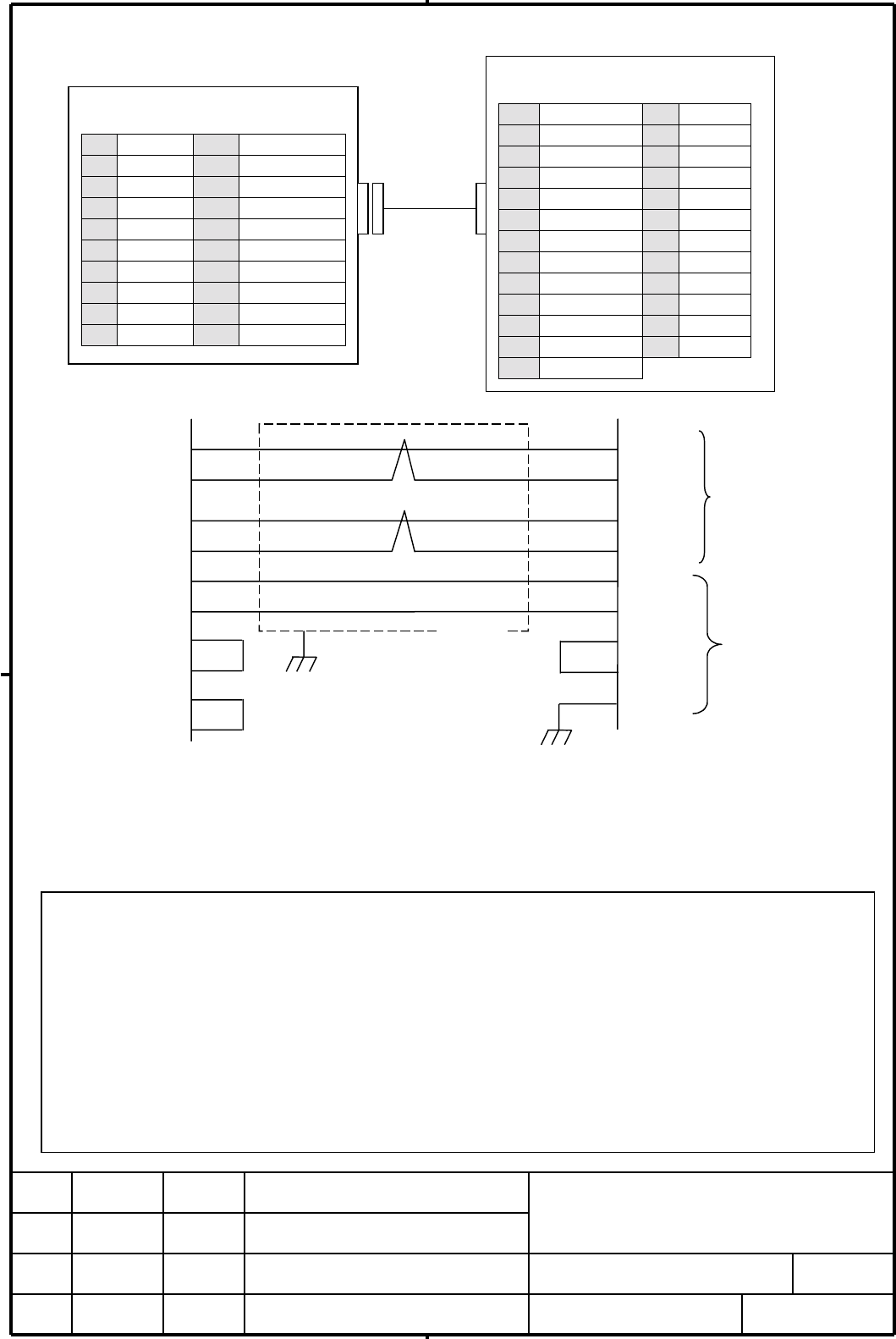
4.1 The details of the Display link cable J183
Recommended wire: A66L-0001-0284#10P (#28AWG 10 pairs, batch shield ) <HITACH, OKI telegraph>
Recommended connector JD41/JD45/JD14 side connector: PCR-E20FS and PCR-E20FA
housing : PCR-V20LA <HONDA communication>
Recommended connector CA72 side connector : DBM-25S
lock metal fittings : D20418-J9 <HONDA communication>
The largest length of the cable : The cable J183 added to J182 is 50m
22
23
8
9
17
18
15
1
1
2
3
4
11
12
13
14
15
16
RXD
*RXD
TXD
*TXD
0V
0V
0V
Shell
FG
CNC JD41/JD45
(PCR-EV20MDT)
1RXD11 0V
2*RXD12 0V
3TXD13 RXTM1
4*TXD14 RXTM2
5 15 TXTM1
6 16 TXTM2
7 17
8 18
9 19
10 20
RXD
*RXD
TXD
*TXD
0V
0V
RXTM1
RXTM2
TXTM1
TXTM2
JD41/JD45
#28AWG
twist
p
air
shield
#
28AWG
CA72
J183
Note
1.
The FG pin of connector CA72 is connected to the cabinet.
2.
In the case of the interface JD41 of Power Mate i and the interface JD45 of i series CNC, the
terminal of link for CNC side is done with the shorting 13 pin and 14 pin, 15 pin and 16 pin. In the
case of the interface JD14 of Power Mate-D, the terminal of link for CNC side is done with
terminal unit of CRT link. When the detachable LCD/MDI is connected to only one Power Mate-D,
the shorting 13 pin and 14 pin, 15 pin and 16 pin is OK.
3.
The connection of shell of connector CA72 to 0V is for detachable connection. The 0V of CNC
must be connected to the 0V of detachable LCD/MDI at first.
Terminal unit CA72
(DBM-25S)
1FG14
2 (VDR) 15 0V
3 (VDG) 16 (0V)
4 (VDB) 17 0V
5 (VSYNC) 18 0V
6(HSYNC)19 (0V)
7 20 (0V)
8TXD21 (0V)
9*TXD22 RXD
10 23 *RXD
11 24
12 25
13
Contents Summary of Connecting manual for detachable LCD/MDI Type B Additional Manual
- Page 1TECHNICAL REPORT (MANUAL) No. TMN00/171E Date 2000.Nov.02 General Manager of Hardware Laboratory Detachable LCD/MDI Type B 1 Communicate this report to : ! Your information ! GE Fanuc-N, GE Fanuc-E FANUC Robotics MILACRON ! Machine tool builder Sales agency End user 2 Summary for Sales Documents Thi
- Page 2Connection material of Detachable LCD/MDI Type B 1. Outline The detachable LCD/MDI Type B is 8.4” LCD/MDI unit integrated in a portable box. The detachable LCD/MDI Type B has the following merits. • Compared to a usual detachable LCD/MDI, it is very thin and about half of weight. • It can be connect
- Page 32. Specifications Indicator 8.4” TFT 40 characters by ×16 lines External dimensions 445 (W) × 229 (H) × 122 (D) ; Not including connection cables Weight 3.5 kg ; excluding connection cables Power supply AC100V to 240V Electric capacity 0.5A (AC100V) 0.25A (AC200V) Interface Display link(CRT link) 1
- Page 44. The connection method in case of Display link In case of connecting to the detachable LCD/MDI via the Display link to Power Mate, 16i / 18i / 21i, etc, refer to the following. •The cable J182 and J169 are connected to the detachable LCD/MDI previously. •The cable J183 and J168 are connected to th
- Page 54.1 The details of the Display link cable J183 Terminal unit CA72 (DBM-25S) CNC JD41/JD45 1 FG 14 (PCR-EV20MDT) 2 (VDR) 15 0V 1 RXD 11 0V 3 (VDG) 16 (0V) 2 *RXD 12 0V 4 (VDB) 17 0V 3 TXD 13 RXTM1 J183 5 (VSYNC) 18 0V 4 *TXD 14 RXTM2 6 (HSYNC) 19 (0V) 5 15 TXTM1 7 20 (0V) 6 16 TXTM2 8 TXD 21 (0V) 7 1
- Page 64.2 The details of Display link cable J182 Detachable LCD/MDI CA72 Detachable LCD/MDI CA61 (DBM-25S) (DBM-25S-0001) 1 FG 14 1 FG 14 2 VDR 15 0V 2 VDR 15 0V 3 VDG 16 0V 3 VDG 16 0V J182 4 VDB 17 0V 4 VDB 17 0V 5 VSYNC 18 0V 5 VSYNC 18 0V 6 HSYNC 19 0V 6 HSYNC 19 0V 7 20 0V 7 20 0V 8 TXD 21 0V 8 TXD 2
- Page 74.3 The detail of power supply cable J168 1) In case of 100VAC Terminal CPA for 100VAC power 100VAC supply J168 Contact ground type 0.5A 2 pole 50Hz/60Hz 1-ph 15A 125V R R 100A 100A S S 100B 100B G G G G G 2) In case of 200VAC Terminal CPA for 200VAC power J168 200VAC supply Contact ground type 0.25
- Page 84.4 The detail of power supply cable J169 1) In case of AC100V Terminal panel Detachable LCD/MDI CPA CA63 (contact ground type (JL04V-2E10SL-3PE-B) 2pole 15A 125V) J169 R 100A R 100A S 100B S 100B G G G G R R 100A 100A S S 100B 100B G G G G 2) In case of AC200V Terminal panel Detachable LCD/MDI CPA
- Page 95. The connection method in case of Video signal / MDI signal In case of connection to the detachable LCD/MDI to CNC like FS16/18/21 via the interface of video signal/MDI signal, it is as following. •The cables J182, J171 and J169 are connected to the Detachable LCD/MDI beforehand. •The cables J185
- Page 105.1 Detail of video signal cable J185 Terminal unit CA72 CNC JA1 (DBM-25S) (PCR-EV20MDT) 1 FG 14 1 VDR 11 2 VDR 15 0V 2 0V 12 VSYNC 3 VDG 16 0V 3 VDG 13 J185 4 VDB 17 0V 4 0V 14 0V 5 VSYNC 18 0V 5 VDG 15 6 HSYNC 19 0V 6 0V 16 0V 7 20 0V 7 17 8 (TXD) 21 0V 8 18 HSYNC 9 (*TXD) 22 (RXD) 9 19 10 23 (*RX
- Page 115.2 The detail of MDI signal cable J170 CNC JA2 (PCR-EV20MDT) Terminal panel CA73 1 *SW0 11 *SW1 (MR-20RF) 2 *SW2 12 *SW3 1 8 *CM2 14 3 *SW4 13 *SW5 2 *CM0 9 *CM3 15 *CM5 4 *SW6 14 *SW7 3 *CM1 10 *SW7 16 *CM6 J170 5 *CM0 15 *CM1 4 *SW6 11 *SW5 17 *CM7 6 *CM2 16 *CM3 5 *SW4 12 *SW3 18 *CM4 7 *CM4 17
- Page 125.3 The details of MDI signal cable J171 Terminal panel CA73 Detachable LCD/MDI CA62 (MR-20RF) 04 03 02 01 1 8 *CM2 14 2 *CM0 9 *CM3 15 *CM5 *CM3 *CM2 *CM1 *CM0 J171 3 *CM1 10 *SW7 16 *CM6 10 09 08 07 06 05 4 *SW6 11 *SW5 17 *CM7 *SW2 *SW1 *SW0 FG 5 *SW4 12 *SW3 18 *CM4 6 *SW2 13 *SW1 19 *CM8 16 15
- Page 135.5 The detail of power supply cable J168 Please refer to subsection 4.3 5.6 The detail of power supply cable J169 Please refer to subsection 4.4 6. The note for cables 1) Please do not connect to the opening pins and pins with ( ). 2) Don’t change the object of the twist pair. Don’t change the obje
- Page 146) The setting of using small MDI may be necessary with kind of CNC. 7) The picture Display function is not available, when the detachable LCD/MDI Type B is used. 8) When the system alarm is occurred on the Power Mate, the display is not changed. 9) The brightness of LCD is fallen when room temperat
- Page 15Supplement A External picture 214 15 445 122 Supplement B Seal 1) In case of connection with video signal/MDI signal, please put the following seal near the terminal unit and the connector of the cable in the cabinet. It is for showing the position A of switch. SW1 : A A02B-0166-K030 (50 peace per o