AC Servo Motor Alpha i/is Series Descriptions Page 54
Descriptions
2.HOW TO USE SERVO MOTORS SPECIFICATIONS FOR THE αiS/αi SERIES B-65262EN/03
- 36 -
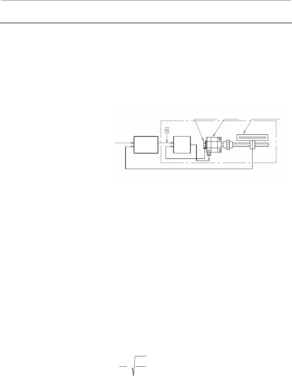
2.3.5 Precautions for Using Linear Scale
In the case where the machine moves in a linear direction and
movement is directly detected by linear scale such as inductosyn,
magne-scale etc., special considerations are necessary in comparison
with the method where feedback is produced by detecting the motor
shaft rotation. This is because the machine movement now directly
influences the characteristics of the control system.
Machine system natural frequency
The following block diagram shows feedback produced using a linear
scale.
Motor
Pulse coder Linear scale
Command
Position
control
circuit
Velocity
control
circuit
The response of this control system is determined by the adjustment
value (position loop gain) of the position control circuit. In other
words, the position loop gain is determined by the specified response
time of the control system. In the diagram above, the section enclosed
by the broken line is called the velocity loop.
Unless the response time of this section where position signal is
detected is sufficiently shorter than the response time determined by
the position loop gain, the system does not operate properly. In other
words, when a command signal is put into point A, response time of
the machine where position signals are detected must be sufficiently
shorter than the response time defined by the position loop gain.
If the response of the sensor section is slow, the position loop gain
should be reduced to have the system operate normally, and as a result,
the response of the whole system becomes slow. The same problem is
caused when inertia is great.
The main causes for slow response are the mass of the machine and
the elastic deformation of the machine system. The larger the volume,
and the greater the elastic deformation, the slower the response
becomes.
As an index for estimating the response of this machine system, the
natural frequency of the machine is used, and this is briefly calculated
by the following equation.
L
J
m
K
m
W ×=
π
2
1
W
m
: Natural frequency
J
L
: Load inertia reflected to motor shaft
K
m
: Rigidity of machine system
(=Torque necessary to elastically deform 1[rad] at the
motor shaft when the machine table is clamped.)
Contents Summary of AC Servo Motor Alpha i/is Series Descriptions
- Page 1FANUC AC SERVO MOTOR @*s series FANUC AC SERVO MOTOR @* series DESCRIPTIONS B-65262EN/03�
- Page 2Ȧ No part of this manual may be reproduced in any form. Ȧ All specifications and designs are subject to change without notice. In this manual we have tried as much as possible to describe all the various matters. However, we cannot describe all the matters which must not be done, or which cannot be
- Page 3B-65262EN/03 SAFETY PRECAUTIONS SAFETY PRECAUTIONS This "Safety Precautions" section describes the precautions which must be observed to ensure safety when using FANUC AC servo motors. Users of any servo motor model are requested to read this "Safety Precautions" carefully before using the servo mot
- Page 4SAFETY PRECAUTIONS B-65262EN/03 1.1 DEFINITION OF WARNING, CAUTION, AND NOTE This manual includes safety precautions for protecting the user and preventing damage to the machine. Precautions are classified into Warning and Caution according to their bearing on safety. Also, supplementary information
- Page 5B-65262EN/03 SAFETY PRECAUTIONS 1.2 WARNING WARNING - Be safely dressed when handling a motor. Wear safety shoes or gloves when handling a motor as you may get hurt on any edge or protrusion on it or electric shocks. - Use a crane or lift to move a motor from one place to another. Motors are heavy.
- Page 6SAFETY PRECAUTIONS B-65262EN/03 WARNING - Connect power wires securely so that they will not get loose. Securely connect power wires and short bars to the terminal block with the specified tightening torque according to the procedures described in this manual. If a motor runs with a wire loosely con
- Page 7B-65262EN/03 SAFETY PRECAUTIONS - Be careful not get your hair or cloths caught in a fan. Be careful especially for a fan used to generate an inward air flow. Be careful also for a fan even when the motor is stopped, because it continues to rotate while the amplifier is turned on. - Ensure that moto
- Page 8SAFETY PRECAUTIONS B-65262EN/03 1.3 CAUTION CAUTION - FANUC motors are designed for use with machines. Do not use them for any other purpose. If a FANUC motor is used for an unintended purpose, it may cause an unexpected symptom or trouble. If you want to use a motor for an unintended purpose, previ
- Page 9B-65262EN/03 SAFETY PRECAUTIONS - Be sure to attach a key to a motor with a keyed shaft. If a motor with a keyed shaft runs with no key attached, it may impair torque transmission or cause imbalance, resulting in the motor being broken. s-7�
- Page 10SAFETY PRECAUTIONS B-65262EN/03 1.4 NOTE NOTE - Do not step or sit on a motor. If you step or sit on a motor, it may get deformed or broken. Do not put a motor on another unless they are in packages. - When storing a motor, put it in a dry (non-condensing) place at room temperature (0 to 40 °C). If
- Page 11B-65262EN/03 SAFETY PRECAUTIONS NOTE - Do not apply a commercial power source voltage directly to a motor. Applying a commercial power source voltage directly to a motor may result in its windings being burned. Be sure to use a specified amplifier for supplying voltage to the motor. - For a motor wi
- Page 12
- Page 13B-65262EN/03 PREFACE PREFACE This manual describes the specifications and characteristics of the αis and αi series servo motors. The manual consists of the following chapters: I. Specifications for the αis/α αi series This chapter provides a general description of the αis and αi series, including ho
- Page 14PREFACE B-65262EN/03 Related manuals The following six kinds of manuals are available for FANUC SERVO MOTOR αis/αi series. In the table, this manual is marked with an asterisk (*). Document Document name Major contents Major usage number Specification FANUC AC SERVO MOTOR αis series Characteristics
- Page 15B-65262EN/03 TABLE OF CONTENTS TABLE OF CONTENTS SAFETY PRECAUTIONS .......................................................................... s-1 PREFACE.................................................................................................. p-1 I. SPECIFICATIONS FOR THE αis/αi SERIES 1 G
- Page 16TABLE OF CONTENTS B-65262EN/03 3.3 HOW TO FILL IN THE SERVO MOTOR SELECTION DATA TABLE.........66 3.3.1 Servo Motor Selection Data Table ........................................................................ 66 3.3.2 Explanation of Items.............................................................
- Page 17B-65262EN/03 TABLE OF CONTENTS 6.3 CAUTIONS ................................................................................................104 6.4 REDUCING THE BRAKE SHAFT FALL AMOUNT....................................105 7 COOLING FAN...............................................................
- Page 18TABLE OF CONTENTS B-65262EN/03 V. FANUC AC SERVO MOTOR α(HV)i SERIES 1 GENERAL ..........................................................................................243 2 TYPES OF MOTORS AND DESIGNATION .......................................244 3 SPECIFICATIONS AND CHARACTERISTICS..............
- Page 19I. SPECIFICATIONS FOR THE αis/α αi SERIES
- Page 20
- Page 21B-65262EN/03 SPECIFICATIONS FOR THE αiS/αi SERIES 1.GENERAL 1 GENERAL -3-
- Page 221.GENERAL SPECIFICATIONS FOR THE αiS/αi SERIES B-65262EN/03 1.1 FEATURE The FANUC AC Servo Motor αis series and αi series has been designed for machine tool feed axis applications. This servo motor αi series has the following features: Smooth rotation The special magnetic pole shape minimizes torque
- Page 23B-65262EN/03 SPECIFICATIONS FOR THE αiS/αi SERIES 1.GENERAL 1.2 LINEUP OF THE SERIES The FANUC AC Servo Motor αis and αi series consist of the following series, each of which has the listed characteristics. Torque Series Feature Applications (N⋅⋅m) αis 2 to 500 High acceleration models for high-spee
- Page 242.HOW TO USE SERVO MOTORS SPECIFICATIONS FOR THE αiS/αi SERIES B-65262EN/03 2 HOW TO USE SERVO MOTORS This chapter describes the limitation on the environment in which the FANUC AC servo motor αis series or αi series is used, how to connect the servo motor to the CNC system, and how to install the s
- Page 25B-65262EN/03 SPECIFICATIONS FOR THE αiS/αi SERIES 2.HOW TO USE SERVO MOTORS 2.1 USE ENVIRONMENT FOR SERVO MOTORS 2.1.1 Ambient Environment Ambient temperature The ambient temperature should be 0°C to 40°C. When operating the machine at a higher temperature, it is necessary to lower the output power
- Page 262.HOW TO USE SERVO MOTORS SPECIFICATIONS FOR THE αiS/αi SERIES B-65262EN/03 Drip-proof environment The level of motor protection is such that a single motor unit can satisfy IP65 of the IEC standard. (The fan-equipped models is excluded.) However, this standard relates only to short-term performance
- Page 27B-65262EN/03 SPECIFICATIONS FOR THE αiS/αi SERIES 2.HOW TO USE SERVO MOTORS Oil seal section requirements The motor shaft is sealed to prevent penetration of oil into the motor housing. However, sealing may not be perfect under severe working conditions. When oil bath lubrication is provided for the
- Page 282.HOW TO USE SERVO MOTORS SPECIFICATIONS FOR THE αiS/αi SERIES B-65262EN/03 The motor shaft oil seal diameter is as shown below. Motor mode Oil seal diameter α2iS, α2HViS α4iS, α4HViS φ15 [mm] α1i α2i α8iS, α8HViS α12iS, α12HViS φ24 [mm] α4i, α4HVi α8i, α8HViS α22iS, α22HViS α30iS, α30HViS α40iS, α4
- Page 29B-65262EN/03 SPECIFICATIONS FOR THE αiS/αi SERIES 2.HOW TO USE SERVO MOTORS 2.1.2 Checking a Delivered Servo Motor and Storing a Servo Motor When the servo motor is delivered, check the following items. • The motor meets the specifications. (Specifications of the model/shaft/sensor) • Damage caused
- Page 302.HOW TO USE SERVO MOTORS SPECIFICATIONS FOR THE αiS/αi SERIES B-65262EN/03 2.1.3 Separating and Disposing of a Servo Motor For a servo motor, a plastic part is used. Disassemble the motor as shown in the following figure, separate the plastic part (Pulsecoder cover), and dispose of the motor. The f
- Page 31B-65262EN/03 SPECIFICATIONS FOR THE αiS/αi SERIES 2.HOW TO USE SERVO MOTORS 2.2 CONNECTING A SERVO MOTOR 2.2.1 Applicable Amplifiers The FANUC AC Servo Motor αis/αi series can be driven using FANUC Servo Amplifier αi series. CAUTION 1 If a motor is used in a combination other than those listed above
- Page 322.HOW TO USE SERVO MOTORS SPECIFICATIONS FOR THE αiS/αi SERIES B-65262EN/03 2.2.2 Connections Related to a Servo Motor For the FANUC AC Servo Motor αis/αi series, connect the power line of the motor and the signal line of a Pulsecoder to an FANUC Servo Amplifier. When the motor has a built-in brake
- Page 33B-65262EN/03 SPECIFICATIONS FOR THE αiS/αi SERIES 2.HOW TO USE SERVO MOTORS CAUTION 1 When connecting the power line to the terminal block of a motor, tighten the screw with the following torque: Terminal size Tightening torque M4 1.1 N⋅m to 1.5 N⋅m M5 2.0 N⋅m to 2.5 N⋅m M6 3.5 N⋅m to 4.5 N⋅m M8 8.0
- Page 342.HOW TO USE SERVO MOTORS SPECIFICATIONS FOR THE αiS/αi SERIES B-65262EN/03 2.2.3 Connector 2.2.3.1 Connectors on the motor side For the FANUC AC Servo Motor αis series or αi series, a TUV- approved connector is used as the power line connector to meet the IEC60034 standard. For this power line conn
- Page 35B-65262EN/03 SPECIFICATIONS FOR THE αiS/αi SERIES 2.HOW TO USE SERVO MOTORS Fan connectors Motor Type For Fan JN2AS04MK1X α50/3000iS with fan, α300/2000iS, α500/2000iS, α40/3000i with fan (Japan Aviation Electronics α50/3000HViS with fan, α300/2000HViS , α500/2000HViS, α1000/2000HViS Industry) CAUTI
- Page 362.HOW TO USE SERVO MOTORS SPECIFICATIONS FOR THE αiS/αi SERIES B-65262EN/03 2.2.3.2 Connectors on the cable side (for signal : all models of the αis/α αi series) A small dedicated connector common to all servo motors of the αis, αi series is used. The connector is dripproof when engaged with the mot
- Page 37B-65262EN/03 SPECIFICATIONS FOR THE αiS/αi SERIES 2.HOW TO USE SERVO MOTORS The outside dimensions of each type of connector when engaged are shown below: Elbow type Straight type CAUTION 1 In case that the cable is prepared by MTB, total resistance of 5V and 0V must be less than 2Ω. 2 Pulsecoder si
- Page 382.HOW TO USE SERVO MOTORS SPECIFICATIONS FOR THE αiS/αi SERIES B-65262EN/03 2.2.3.3 Connectors on the cable side (for power and brake : models α2is to α4is and α1i to α2i) Dedicated connectors which are TUV approved are available as the connector for power for the α2is to α4is and α1i to α2i. These
- Page 39B-65262EN/03 SPECIFICATIONS FOR THE αiS/αi SERIES 2.HOW TO USE SERVO MOTORS 2.2.3.4 Connectors on the cable side (for power : models α8is to α50is or α4i to α40i) To meet the IEC60034 standard, TUV-approved plug connectors and cable clamps should be used in connecting the power cable. To meet the IE
- Page 402.HOW TO USE SERVO MOTORS SPECIFICATIONS FOR THE αiS/αi SERIES B-65262EN/03 Specifications of plug connectors on the cable side (support for waterproof IP67, TUV-approved type) Specifications of Plug Connectors on the Cable Side (Waterproof TUV-approved Type) [D] Single Block [A] Straight Type [B] E
- Page 41B-65262EN/03 SPECIFICATIONS FOR THE αiS/αi SERIES 2.HOW TO USE SERVO MOTORS CAUTION 1 TUV have certified that the plug connectors and cable clamps listed above, when combined with the FANUC AC Servo Motor αis series and αi series, satisfy the VDE0627 safety standard. Several manufacturers offer othe
- Page 422.HOW TO USE SERVO MOTORS SPECIFICATIONS FOR THE αiS/αi SERIES B-65262EN/03 Specifications of plug connectors on the cable side (support for waterproof IP67) Specifications of Plug Connectors on the Cable Side (Waterproof Type) [D] Single Block [A] Straight Type [B] Elbow Type Plug Model Name [C] Ca
- Page 43B-65262EN/03 SPECIFICATIONS FOR THE αiS/αi SERIES 2.HOW TO USE SERVO MOTORS 2.2.3.5 Connectors on the cable side (for brake : models α8is to α200is and α4i to α40i) The models α8is to α200is and α4i to α40i use a dedicated connector to connect the built-in brake cable. This connector is dripproof. I
- Page 442.HOW TO USE SERVO MOTORS SPECIFICATIONS FOR THE αiS/αi SERIES B-65262EN/03 2.2.3.6 Connectors on the cable side (for fan : models α50is(with fan) to α1000HVis and α40i(with fan)) The models α50is (with fan) to α1000HVis and α40i (with fan) use a dedicated connector to connect the cooling fan and po
- Page 45B-65262EN/03 SPECIFICATIONS FOR THE αiS/αi SERIES 2.HOW TO USE SERVO MOTORS 2.2.3.7 Connection to a conduit hose This section gives information on the specifications of several adapters to be connected that are made by conduit hose manufacturers for reference purposes. Before using an adapter, conta
- Page 462.HOW TO USE SERVO MOTORS SPECIFICATIONS FOR THE αiS/αi SERIES B-65262EN/03 [E] Cable [F] Cable [G] Conduit hose [H] Conduit hose Model Name Seal adapter Seal adapter Seal adapter Seal adapter Straight type Elbow type Straight type Elbow type For signal N2KY16-FN3 (SANKEI) PCJN-12-M13F Common to all
- Page 47B-65262EN/03 SPECIFICATIONS FOR THE αiS/αi SERIES 2.HOW TO USE SERVO MOTORS 2.3 COUPLING A SERVO MOTOR 2.3.1 Coupling a Servo Motor and Machine In many cases, the following four methods are used for coupling the motor shaft to the ball screw on a machine: Direct connection through a flexible couplin
- Page 482.HOW TO USE SERVO MOTORS SPECIFICATIONS FOR THE αiS/αi SERIES B-65262EN/03 Direct connection using a flexible coupling Direct connection by a flexible coupling has the following advantages over connection using gears: • Even if the angle of the motor shaft to the ball screw changes, it can be compe
- Page 49B-65262EN/03 SPECIFICATIONS FOR THE αiS/αi SERIES 2.HOW TO USE SERVO MOTORS Direct connection using a rigid coupling Direct connection using a rigid coupling has the following advantages over direct connection using a flexible coupling: • More economical • The coupling rigidity can be increased. • I
- Page 502.HOW TO USE SERVO MOTORS SPECIFICATIONS FOR THE αiS/αi SERIES B-65262EN/03 Timing belt A timing belt is used in the same cases as gear connection, but in comparison, it has advantages such as low cost and reduced noise during operation, etc. However, it is necessary to correctly understand the char
- Page 51B-65262EN/03 SPECIFICATIONS FOR THE αiS/αi SERIES 2.HOW TO USE SERVO MOTORS 2.3.2 Allowable Axis Load for a Servo Motor The allowable axis load on a motor shaft is given in the specifications of the relevant motor in Part II and afterward. Using a motor under a load higher than the allowable axial l
- Page 522.HOW TO USE SERVO MOTORS SPECIFICATIONS FOR THE αiS/αi SERIES B-65262EN/03 2.3.3 Axis Run-out Precision of a Servo Motor The axis run-out precision of a servo motor is given in the specifications of the motor in Part II and afterward. The methods of measuring the axis run-out precision are specifie
- Page 53B-65262EN/03 SPECIFICATIONS FOR THE αiS/αi SERIES 2.HOW TO USE SERVO MOTORS 2.3.4 Machine Movement per 1 Revolution of Motor Shaft The machine movement per 1 revolution of motor shaft must be determined at the first stage of machine design referring the load torque, load inertia, rapid traverse spee
- Page 542.HOW TO USE SERVO MOTORS SPECIFICATIONS FOR THE αiS/αi SERIES B-65262EN/03 2.3.5 Precautions for Using Linear Scale In the case where the machine moves in a linear direction and movement is directly detected by linear scale such as inductosyn, magne-scale etc., special considerations are necessary
- Page 55B-65262EN/03 SPECIFICATIONS FOR THE αiS/αi SERIES 2.HOW TO USE SERVO MOTORS The above values can be obtained by calculating the elastic deformation for each section of the driving system. The machine should be designed so that the value of this natural frequency [Hz] will be more than or equal to th
- Page 562.HOW TO USE SERVO MOTORS SPECIFICATIONS FOR THE αiS/αi SERIES B-65262EN/03 2.3.6 Cautions in Mounting a Servo Motor The servo motor contains precision sensor, and is carefully machined and assembled to provide the required precision. Pay attention to the following items to maintain the precision an
- Page 57B-65262EN/03 SPECIFICATIONS FOR THE αiS/αi SERIES 2.HOW TO USE SERVO MOTORS A precision sensor is directly connected to the servo motor shaft. Pay attention to the following items to prevent damage to the sensor. • When connecting the power transmission elements such as a gear, a pulley and a coupli
- Page 582.HOW TO USE SERVO MOTORS SPECIFICATIONS FOR THE αiS/αi SERIES B-65262EN/03 • When tapping slightly to remove the tightly contacted tapered surface, tap in the radial direction to prevent a shock in the axial direction. • Suppress the rotary unbalance of the connected power transmission element to t
- Page 59B-65262EN/03 SPECIFICATIONS FOR THE αiS/αi SERIES 3.SELECTING A MOTOR 3 SELECTING A MOTOR A servo motor should be selected based on the load on the servo motor, rapid traverse rate, increment system, and other conditions. Motors are subjected to the following types of torque: constant load torque (i
- Page 603.SELECTING A MOTOR SPECIFICATIONS FOR THE αiS/αi SERIES B-65262EN/03 3.1 CONDITIONS FOR SELECTING A SERVO MOTOR The conditions for selecting a servo motor are given below. [Selection condition 1] Constant load torque - The constant load torque including mechanical friction and gravity must fall wit
- Page 61B-65262EN/03 SPECIFICATIONS FOR THE αiS/αi SERIES 3.SELECTING A MOTOR [Selection condition 4] Acceleration torque - Acceleration can be made with a desired time constant. Since the load torque generally helps deceleration, if acceleration can be executed with a desired time constant, deceleration ca
- Page 623.SELECTING A MOTOR SPECIFICATIONS FOR THE αiS/αi SERIES B-65262EN/03 NOTE When handling units, be extremely careful not to use different systems of units. For example, the weight of an object should be expressed in [kg] in the SI system of units because it is handled as "mass" or [kgf] in the gravi
- Page 63B-65262EN/03 SPECIFICATIONS FOR THE αiS/αi SERIES 3.SELECTING A MOTOR 3.2 SELECTING A MOTOR Sample model for calculations for selecting a servo motor The following subsections explain how to calculate conditions for selecting a servo motor best suited for a table with a horizontal axis with the foll
- Page 643.SELECTING A MOTOR SPECIFICATIONS FOR THE αiS/αi SERIES B-65262EN/03 3.2.1 Calculating the Load Torque When a part moves along an axis at a constant speed, the torque obtained by multiplying the weight of the workpiece driving section by the friction coefficient is always applied. On a vertical or
- Page 65B-65262EN/03 SPECIFICATIONS FOR THE αiS/αi SERIES 3.SELECTING A MOTOR Cautions in calculating the load torque When calculating the torque, take the following precautions: • Allow for the friction torque caused by the gib fastening force (Fg). The torque calculated only from the weight of a movable p
- Page 663.SELECTING A MOTOR SPECIFICATIONS FOR THE αiS/αi SERIES B-65262EN/03 3.2.2 Calculating the Motor Speed Calculate the motor speed using the movable part rapid traverse rate and traveling distance per revolution of the motor and check that the calculated motor speed does not exceed the maximum motor
- Page 67B-65262EN/03 SPECIFICATIONS FOR THE αiS/αi SERIES 3.SELECTING A MOTOR 3.2.3 Calculating the load inertia Unlike the load torque, an accurate load inertia can be obtained just by calculation. The inertia of all objects moved by the revolution of a driving motor forms the load inertia of the motor. It
- Page 683.SELECTING A MOTOR SPECIFICATIONS FOR THE αiS/αi SERIES B-65262EN/03 Inertia of a heavy object moving along a straight line (table, workpiece, etc.) SI unit 2 æ l ö J = W ×ç ÷ [kg ⋅ m 2 ] b è 2π ø W : Weight of the object moving along a straight line [kg] l : Traveling distance along a straight lin
- Page 69B-65262EN/03 SPECIFICATIONS FOR THE αiS/αi SERIES 3.SELECTING A MOTOR Inertia of a cylindrical object in which the center of rotation is displaced Center of rotation 2 J = J 0 + MR J0 : Inertia around the center of the object M : Weight of the object R : Radius of rotation The above equation is used
- Page 703.SELECTING A MOTOR SPECIFICATIONS FOR THE αiS/αi SERIES B-65262EN/03 [Example of calculation for condition 3] Load inertial ratio In this example, the sum of Jb and Jw obtained above is the load inertia (JL). JL = 0.00196 + 0.01216 = 0.01412 [kg⋅m2] The motor inertial of the α22/4000is is 0.0053 [k
- Page 71B-65262EN/03 SPECIFICATIONS FOR THE αiS/αi SERIES 3.SELECTING A MOTOR 3.2.4 Calculating the Acceleration Torque Calculate the acceleration torque required for the motor to accelerate and then obtain the torque required for acceleration by calculating the total torque including the constant load torq
- Page 723.SELECTING A MOTOR SPECIFICATIONS FOR THE αiS/αi SERIES B-65262EN/03 [Example of calculation for condition 4-1] Example of calculation Try to perform linear acceleration/deceleration under the following condition. Vm=3000 [min-1] ta=0.1 [s] ks=30 [s-1] JL=0.01412 [kg⋅m2] Select the α22/4000is provi
- Page 73B-65262EN/03 SPECIFICATIONS FOR THE αiS/αi SERIES 3.SELECTING A MOTOR 2π 1 Ta = Vm × × × (J M + J L /ηη 60 t1 t2 Vr = Vm × ( 1 − ) 2t 1 2π 1 Acc a = Vm × × × P 60 t1 Ta : Acceleration torque [N⋅m] Vm : Motor speed in rapid traverse [min-1] t1 : Acceleration time constant T1 [sec] t2 : Acceleration t
- Page 743.SELECTING A MOTOR SPECIFICATIONS FOR THE αiS/αi SERIES B-65262EN/03 3.2.4.2 Calculating the torque required by the motor shaft in acceleration To obtain the torque required by the motor shaft (T), add the constant load torque (Tm) to the acceleration torque (Ta). T = Ta + Tm T : Torque required by
- Page 75B-65262EN/03 SPECIFICATIONS FOR THE αiS/αi SERIES 3.SELECTING A MOTOR The speed-torque characteristics of the α30/4000is, given below, show that the point of 86.2 [N⋅m]/2050 [min-1] is within the intermittent operating zone of the α30/4000is (acceleration is possible). Speed - torque characteristics
- Page 763.SELECTING A MOTOR SPECIFICATIONS FOR THE αiS/αi SERIES B-65262EN/03 3.2.5 Calculating the Root-mean-square Value of the Torques A motor gets hot in proportion to the square of the torque. For a servo motor for which the load condition always changes, the calculated root-mean-square value of torque
- Page 77B-65262EN/03 SPECIFICATIONS FOR THE αiS/αi SERIES 3.SELECTING A MOTOR [Example of calculation for condition 5] Root-mean-square value of the torques Example) α30/4000iS ( Ts = 3.0[N⋅m] = 306[kgf⋅cm] ), Ta = 83.2[N⋅m], Tm = To = 3.0[N⋅m], t1 = 0.08[sec], t2 = 2.0[sec], t3 = 3.0[sec] Trms = (83.2 + 3.
- Page 783.SELECTING A MOTOR SPECIFICATIONS FOR THE αiS/αi SERIES B-65262EN/03 3.2.6 Calculating the Percentage Duty Cycle and ON Time with the Maximum Cutting Torque Confirm that the time (duty percentage and ON time) during which the maximum cutting torque can be applied for cutting is shorter than the des
- Page 79B-65262EN/03 SPECIFICATIONS FOR THE αiS/αi SERIES 3.SELECTING A MOTOR Calculating the percentage duty cycle with the maximum cutting torque Torque Maximum cutting torque (Tms) Time If the load torque (Tms) is greater than the product of the motor stall torque (Ts) and thermal efficiency (α), calcula
- Page 803.SELECTING A MOTOR SPECIFICATIONS FOR THE αiS/αi SERIES B-65262EN/03 3.2.7 Calculating the Dynamic Brake Stop Distance The equation for calculating the coasting distance when an abnormality occurs and the machine tool is stopped by dynamic braking with both ends of the motor power line shorted (dyn
- Page 81B-65262EN/03 SPECIFICATIONS FOR THE αiS/αi SERIES 3.SELECTING A MOTOR [Example of calculation for condition 7] Dynamic brake stop distance Assume that the desired stop distance is 150 mm. Coasting distance = (3000/60×20)[mm/sec]×0.05[sec]+(0.0076[kg⋅m2]+ 0.01412[kg⋅m2])×(4.0×10-2×3000[min-1]+3.1×10-
- Page 823.SELECTING A MOTOR SPECIFICATIONS FOR THE αiS/αi SERIES B-65262EN/03 Coefficients for dynamic brake calculation Gravitational system of SI unit Model units A B A B αiS series -1 -8 -2 -9 α2/5000iS 1.9×10 9.0×10 1.9×10 8.8×10 -2 -8 -3 -9 α4/5000iS 7.6×10 5.4×10 7.4×10 5.2×10 -1 –8 -2 –9 α8/4000iS 1.
- Page 83B-65262EN/03 SPECIFICATIONS FOR THE αiS/αi SERIES 3.SELECTING A MOTOR Gravitational system of SI unit Model units A B A B α(HV)iS series –1 -8 –2 9 α2/5000HViS 3.9×10 4.4×10 3.8×10 4.4×10 –1 -8 –2 –9 α4/5000HViS 2.6×10 1.6×10 2.5×10 1.5×10 –1 –8 –2 –9 α8/4000HViS 1.4×10 1.4×10 1.4×10 1.4×10 –2 -9 –3
- Page 843.SELECTING A MOTOR SPECIFICATIONS FOR THE αiS/αi SERIES B-65262EN/03 3.3 HOW TO FILL IN THE SERVO MOTOR SELECTION DATA TABLE Select a suitable motor according to load conditions, rapid traverse rate, increment system and other factors. To aid in selecting the correct motor, we recommend filling in
- Page 85B-65262EN/03 SPECIFICATIONS FOR THE αiS/αi SERIES 3.SELECTING A MOTOR Servo Motor Selection Data Table SI unit User name Kind of machine tool CNC equipment Type of machine tool Spindle motor Item Axis Specifications of moving object * Weight of moving object (including workpiece, etc.) kg * Axis mov
- Page 863.SELECTING A MOTOR SPECIFICATIONS FOR THE αiS/αi SERIES B-65262EN/03 Servo Motor Selection Data Table Gravitational system of units User name Kind of machine tool CNC equipment Type of machine tool Spindle motor Item Axis Specifications of moving object * Weight of moving object (including workpiec
- Page 87B-65262EN/03 SPECIFICATIONS FOR THE αiS/αi SERIES 3.SELECTING A MOTOR 3.3.2 Explanation of Items 3.3.2.1 Title User name Fill in this blank with the name of the user. Kind of machine tool Fill in this blank with a general name of machine tools, such as lathe, milling machine, machining center, and o
- Page 883.SELECTING A MOTOR SPECIFICATIONS FOR THE αiS/αi SERIES B-65262EN/03 3.3.2.2 Specifications of moving object Be sure to enter data in this row. Data entered here is needed for determining the approximate motor load conditions (inertia, load torque). - Mass(weight) of driven parts Enter the mass(wei
- Page 89B-65262EN/03 SPECIFICATIONS FOR THE αiS/αi SERIES 3.SELECTING A MOTOR - Machine tool efficiency This value is used for calculating the transfer efficiency of motor output on a machine tool. Standard value is 0.9. Generally, a drop in transfer efficiency is expected if a reduction gear having a large
- Page 903.SELECTING A MOTOR SPECIFICATIONS FOR THE αiS/αi SERIES B-65262EN/03 3.3.2.3 Mechanical specifications Enter basic data that is required for selecting the motor. For details on how to calculate each of the items, see Section 3.2. - Movement per rotation of motor Enter the movement of the machine to
- Page 91B-65262EN/03 SPECIFICATIONS FOR THE αiS/αi SERIES 3.SELECTING A MOTOR - Steady-state load torque Enter the torque obtained by calculating the force applied for moving the machine tool and state-state components such as friction (including holding torque in the case of a gravity shaft) reflected on t
- Page 923.SELECTING A MOTOR SPECIFICATIONS FOR THE αiS/αi SERIES B-65262EN/03 - Positioning distance Enter the distance as a condition required for calculating the rapid traverse positioning frequency. When an exclusive positioning device is used, enter this value together with the desired positioning time
- Page 93B-65262EN/03 SPECIFICATIONS FOR THE αiS/αi SERIES 3.SELECTING A MOTOR 3.3.2.4 Motor specifications and characteristics - Motor type Enter the motor type, if desired. - Pulsecoder Enter the specifications (absolute or increment, number of pulses: 1,000,000 or 16,000,000) of the feedback sensor (Pulse
- Page 943.SELECTING A MOTOR SPECIFICATIONS FOR THE αiS/αi SERIES B-65262EN/03 acceleration/deceleration, exponential acceleration/deceleration, or bell-shaped acceleration/deceleration. Enter te only for the time constant in cutting feed. Exponential acceleration/deceleration Speed Vm 0.632Vm te te Time te
- Page 95B-65262EN/03 SPECIFICATIONS FOR THE αiS/αi SERIES 3.SELECTING A MOTOR 3.4 CHARACTERISTIC CURVE AND DATA SHEET Performance of each motor model is represented by characteristic curves and data sheet shown below, which are given in Part II and afterward. 3.4.1 Performance Curves The characteristic curv
- Page 963.SELECTING A MOTOR SPECIFICATIONS FOR THE αiS/αi SERIES B-65262EN/03 Overload duty characteristic The percentage duty cycle indicates the ratio of the time during which torque can be applied to the total time of a single cycle. The ON time indicates the time during which the torque is being applied
- Page 97B-65262EN/03 SPECIFICATIONS FOR THE αiS/αi SERIES 3.SELECTING A MOTOR The duty calculation procedure is shown below: <1> Calculate Torque percent by formula (b) below. <2> Motor can be operated at any point on and inside the curve (according to the limits by overheating or overcurrent alarms) corres
- Page 983.SELECTING A MOTOR SPECIFICATIONS FOR THE αiS/αi SERIES B-65262EN/03 3.4.2 Data Sheet The data sheet gives the values of motor parameters relating to the performance. The values of parameters are those under the following conditions. • The ambient temperature for the motor is 20°C. • The error is ±
- Page 99B-65262EN/03 SPECIFICATIONS FOR THE αiS/αi SERIES 3.SELECTING A MOTOR Torque constant : Kt [N⋅⋅m/Arms] [kgf⋅⋅cm/Arms] This is known as torque sensitivity and represents the torque developed per ampere of phase current. This value is a motor-specific constant, and is calculated by the flux distributi
- Page 1003.SELECTING A MOTOR SPECIFICATIONS FOR THE αiS/αi SERIES B-65262EN/03 Axis friction torque : Tf [N⋅⋅m] [kgf⋅⋅cm] This is the no-load torque required just to rotate the rotor. Mass : w [kg] This is the mass of the motor. The masses of the motor with brakes and that without brakes are indicated. Appli
- Page 101B-65262EN/03 SPECIFICATIONS FOR THE αiS/αi SERIES 4.CONDITIONS FOR APPROVAL RELATED TO THE IEC60034 STANDARD 4 CONDITIONS FOR APPROVAL RELATED TO THE IEC60034 STANDARD This chapter describes the conditions the following FANUC αis and αi series AC servo motors must clear before they can be approved f
- Page 1024.CONDITIONS FOR APPROVAL RELATED TO THE IEC60034 STANDARD SPECIFICATIONS FOR THE αiS/αi SERIES B-65262EN/03 4.1 TYPES OF MOTORS TO BE APPROVED The following FANUC AC Servo Motor αis, αi, α(HV)is, and α(HV)i series can comply with the IEC60034 standard if you follow the descriptions in this chapter.
- Page 103B-65262EN/03 SPECIFICATIONS FOR THE αiS/αi SERIES 4.CONDITIONS FOR APPROVAL RELATED TO THE IEC60034 STANDARD α(HV)is series Model name Motor specification number α2/5000HViS A06B-0213-Bxxx α4/5000HViS A06B-0216-Bxxx α8/4000HViS A06B-0236-Bxxx α12/4000HViS A06B-0239-Bxxx α22/4000HViS A06B-0266-Bxxx α
- Page 1044.CONDITIONS FOR APPROVAL RELATED TO THE IEC60034 STANDARD SPECIFICATIONS FOR THE αiS/αi SERIES B-65262EN/03 4.2 APPROVED SPECIFICATIONS The following specifications are approved for the IEC60034 standard. 4.2.1 Motor Speed (IEC60034-1) The "rated-output speed" and "allowable maximum speed" are give
- Page 105B-65262EN/03 SPECIFICATIONS FOR THE αiS/αi SERIES 4.CONDITIONS FOR APPROVAL RELATED TO THE IEC60034 STANDARD 4.2.3 Protection Type (IEC60034-5) Motor protection confirms to IP65. (Models with fan are not included. The Pulsecoder connector is waterproof when engaged.) IP6x: Completely dust-proof mach
- Page 1064.CONDITIONS FOR APPROVAL RELATED TO THE IEC60034 STANDARD SPECIFICATIONS FOR THE αiS/αi SERIES B-65262EN/03 4.2.5 Mounting Method (IEC60034-7) The motors can be mounted by the following methods. IMB5:Flange mounting with the shaft facing sideways(from the rear) IMV1:Flange mounting with the shaft f
- Page 107B-65262EN/03 SPECIFICATIONS FOR THE αiS/αi SERIES 4.CONDITIONS FOR APPROVAL RELATED TO THE IEC60034 STANDARD 4.3 CONNECTORS REQUIRED FOR APPROVAL Power line connectors (for models α2iS to α4iS and α1i to α2i) The motor power line must be connected using the following specified connectors. Dedicated
- Page 1084.CONDITIONS FOR APPROVAL RELATED TO THE IEC60034 STANDARD SPECIFICATIONS FOR THE αiS/αi SERIES B-65262EN/03 Power line/fan connectors (for models α8iS to α1000HViS and α4i to α40i) ) The motor power cable and brake fan unit must be connected using the connectors and cable clamps specified below. Ca
- Page 109B-65262EN/03 SPECIFICATIONS FOR THE αiS/αi SERIES 5.FEEDBACK SENSOR 5 FEEDBACK SENSOR All AC servo motors contain a Pulsecoder (optical encoder) as a feedback sensor which detects position and velocity. Separate type position sensors are also available for detecting a position by attaching directly
- Page 1105.FEEDBACK SENSOR SPECIFICATIONS FOR THE αiS/αi SERIES B-65262EN/03 5.1 PULSECODER All AC servo motors feature a Pulsecoder (optical encoder). The Pulsecoder outputs position information and an alarm signal. The outline drawing of a Pulsecoder is not given in this section because it is contained in
- Page 111B-65262EN/03 SPECIFICATIONS FOR THE αiS/αi SERIES 5.FEEDBACK SENSOR 5.1.2 Connecting a Pulsecoder Layout of connector pins The signals of the αi series Pulsecoder are arranged as follows: → Pin No. Signal α1000iA name α1000iI α16000iA RD 6 6 *RD 5 5 +5V 8,9 8,9 0V 7,10 7,10 FG 3 3 +6V 4 - Connector
- Page 1125.FEEDBACK SENSOR SPECIFICATIONS FOR THE αiS/αi SERIES B-65262EN/03 5.1.3 Absolute-type Pulsecoder When the NC is turned off, the Pulsecoder position detection function is backed up by battery. So, when the NC is next turned on, the operator does not have to perform reference position return. For ba
- Page 113B-65262EN/03 SPECIFICATIONS FOR THE αiS/αi SERIES 5.FEEDBACK SENSOR 5.2 SEPARATE PULSECODER For detecting a position by attaching directly to a ball screw or a machine, use a separate Pulsecoder. 5.2.1 Separate Pulsecoder Type and Designation Separate Pulsecoder are available. Features and rapid tra
- Page 1145.FEEDBACK SENSOR SPECIFICATIONS FOR THE αiS/αi SERIES B-65262EN/03 5.2.3 Connecting a Separate Type Pulsecoder The layout of connector pins is shown below. For the connection diagram for separate type Pulsecoders, refer to the relevant NC connection manual. Layout of Connector Pins of Pulsecoder αA
- Page 115B-65262EN/03 SPECIFICATIONS FOR THE αiS/αi SERIES 5.FEEDBACK SENSOR 5.2.4 Outline Drawings of Separate Pulsecoder MS connector : MS3102A-20-29P Fig.5.2.4 Pulsecoder αA1000S - 97 -
- Page 1165.FEEDBACK SENSOR SPECIFICATIONS FOR THE αiS/αi SERIES B-65262EN/03 5.2.5 Cautions in Using a Separate Type Pulsecoder Pay attention to the following items when using the separate Pulsecoder. • Increase the machine rigidity between the servo motor and the Pulsecoder to minimize mechanical vibration.
- Page 117B-65262EN/03 SPECIFICATIONS FOR THE αiS/αi SERIES 6.BUILT-IN BRAKE 6 BUILT-IN BRAKE Some models of the AC servo motor αis series and αi series use motors that contain a holding brake to prevent falling along a vertical axis. This chapter explains the specifications of built-in brakes and gives cauti
- Page 1186.BUILT-IN BRAKE SPECIFICATIONS FOR THE αiS/αi SERIES B-65262EN/03 6.1 BRAKE SPECIFICATIONS The specifications of built-in brakes are listed below. α22iS to α50iS α2iS, α4iS α8iS, α12iS α100iS α12i to α40i α1i, α2i α4i, α8i α200iS Motor model Unit (Includes models HV.) (Includes (Includes (Includes
- Page 119B-65262EN/03 SPECIFICATIONS FOR THE αiS/αi SERIES 6.BUILT-IN BRAKE 6.2 CONNECTING A BRAKE 6.2.1 Layout of Connector Pins The following shows the shape and pin arrangement of the brake connectors. Models α2is to α4is and α1i to α2i Connections: 5=BK, 6=BK (Connect to inside of power connector.) (1=U,
- Page 1206.BUILT-IN BRAKE SPECIFICATIONS FOR THE αiS/αi SERIES B-65262EN/03 6.2.2 Connection of the Brakes Configure a brake circuit by referencing the following brake connection diagrams and the recommended parts shown in the following section. To other 24 VDC peripheral devices (such as a relay and solenoi
- Page 121B-65262EN/03 SPECIFICATIONS FOR THE αiS/αi SERIES 6.BUILT-IN BRAKE 6.2.3 Recommended Parts in Brake Circuits The following table lists the recommended parts to be used as components of a brake circuit and their specifications. Models α2is to α50is and α1i to α40i FANUC Name of Name Model No. Specifi
- Page 1226.BUILT-IN BRAKE SPECIFICATIONS FOR THE αiS/αi SERIES B-65262EN/03 6.3 CAUTIONS CAUTION Pay attention to the following points when motors with built-in brakes are used. 1 A built-in brake is used as a holding brake to prevent falling along an axis at servo off. This brake functions as a brake at an
- Page 123B-65262EN/03 SPECIFICATIONS FOR THE αiS/αi SERIES 6.BUILT-IN BRAKE 6.4 REDUCING THE BRAKE SHAFT FALL AMOUNT During use of a motor with a brake, the amount of falling along an axis at a power failure or emergency stop, or when the CNC power supply is turned off during excitation of the motor may beco
- Page 1247.COOLING FAN SPECIFICATIONS FOR THE αiS/αi SERIES B-65262EN/03 7 COOLING FAN Cooling fans are available for the α40i (with fan), α50is (with fan), α50HVis (with fan), α300is, α500is, α300HVis, α500HVis, and α1000HVis. This chapter describes these cooling fans. - 106 -
- Page 125B-65262EN/03 SPECIFICATIONS FOR THE αiS/αi SERIES 7.COOLING FAN 7.1 COOLING FAN SPECIFICATIONS The specifications of the fan supplied with each motor are listed below. α40i (with fan), α50is (with fan), α50HVis (with fan) Single-phase 200 VAC Input voltage 50 Hz 60 Hz 170 to 220 VAC 170 to 242VAC Ra
- Page 1267.COOLING FAN SPECIFICATIONS FOR THE αiS/αi SERIES B-65262EN/03 α1000HVis Motor model α1000/2000is Three-phase 400 VAC Input voltage 50 Hz 60 Hz 320 to 460VAC 320 to 460VAC Rated input 70W 90W Steady-state current 0.75Arms 0.75Arms Protection circuit set temperature 140°C Degree of protection (IEC34
- Page 127B-65262EN/03 SPECIFICATIONS FOR THE αiS/αi SERIES 7.COOLING FAN 7.2 CONNECTING A COOLING FAN 7.2.1 Connection Cables Prepare the connection cables that satisfy the following specifications. α40i (with fan) α50is (with fan), α50HVis (with fan) Connector Straight type JN2DS04FK2X (Japan Aviation Elect
- Page 1287.COOLING FAN SPECIFICATIONS FOR THE αiS/αi SERIES B-65262EN/03 7.2.2 Connection of the Fan Unit The following figure shows how to connect to a fan unit. Note that the input voltage is different for each unit. α40i (with fan) α50is (with fan) α50HVis (with fan) α300is, α500is - 110 -
- Page 129B-65262EN/03 SPECIFICATIONS FOR THE αiS/αi SERIES 7.COOLING FAN α300HVis, α500HVis, α1000HVis - 111 -
- Page 130
- Page 131II. FANUC AC SERVO MOTOR αiS SERIES
- Page 132
- Page 133B-65262EN/03 FANUC AC SERVO MOTOR αiS SERIES 1.GENERAL 1 GENERAL The FANUC AC servo motor αiS series is best suited for the feed axis of a machine tool with high speed and high precision or small machine tool. It has the following features: Excellent acceleration characteristics A high maximum outpu
- Page 1342.TYPES OF MOTORS AND DESIGNATIONFANUC AC SERVO MOTOR αiS SERIES B-65262EN/03 2 TYPES OF MOTORS AND DESIGNATION The types and specifications of αiS series servo motors are described as follows. Models α2/5000iS, α4/5000iS, α8/4000iS, α12/4000iS, α22/4000iS, α30/4000iS, α40/4000iS, and α50/3000iS A06
- Page 135B-65262EN/03 FANUC AC SERVO MOTOR αiS SERIES2.TYPES OF MOTORS AND DESIGNATION Model α50/3000iS with fan A06B-0275-By1z y 0 : Taper shaft 1 : Straight shaft 3 : Taper shaft with the 24VDC brake 4 : Straight shaft with the 24VDC brake z 0 : Pulsecoder α1000iA 1 : Pulsecoder α1000iI 2 : Pulsecoder α160
- Page 1362.TYPES OF MOTORS AND DESIGNATIONFANUC AC SERVO MOTOR αiS SERIES B-65262EN/03 Models α300/2000iS and α500/2000iS A06B-029x-By1z x 2 : Model α300/2000iS 5 : Model α500/2000iS y 0 : Taper shaft z 0 : Pulsecoder α1000iA 1 : Pulsecoder α1000iI 2 : Pulsecoder α16000iA For these models, a straight shaft i
- Page 137B-65262EN/03 FANUC AC SERVO MOTOR αiS SERIES 3.SPECIFICATIONS AND CHARACTERISTICS 3 SPECIFICATIONS AND CHARACTERISTICS This chapter describes the specifications and characteristics of FANUC AC servo motor αiS series. First section describes the common specifications to all motors, and next section d
- Page 1383.SPECIFICATIONS AND CHARACTERISTICS FANUC AC SERVO MOTOR αiS SERIES B-65262EN/03 3.1 COMMON SPECIFICATIONS This section describes the common specifications to FANUC AC servo motor αiS series. Common specifications • Ambient temperature : 0°C to 40°C • Ambient humidity : 80%RH or less (no dew) • Ins
- Page 139B-65262EN/03 FANUC AC SERVO MOTOR αiS SERIES 3.SPECIFICATIONS AND CHARACTERISTICS Shaft runout precision Shaft Rabbet Mounting Motor Model dia. dia. face runout eccentricity runout α2/5000iS Max. Max. Max. α4/5000iS 0.02mm 0.04mm 0.05mm α8/4000iS Max. Max. Max. α12/4000iS 0.02mm 0.04mm 0.05mm α22/40
- Page 1403.SPECIFICATIONS AND CHARACTERISTICS FANUC AC SERVO MOTOR αiS SERIES B-65262EN/03 3.2 CHARACTERISTIC CURVE AND DATA SHEET This section describes the individual specifications and characteristics of FANUC AC servo motor αiS series.in the form of data sheet. For details on these items, refer to "I-3.4
- Page 141B-65262EN/03 FANUC AC SERVO MOTOR αiS SERIES 3.SPECIFICATIONS AND CHARACTERISTICS Model @2/5000*s Specification A06B-0212-B□0□ Speed-Torque Characteristics Over Load Duty 9 100 8 90 110% 7 80 120% 70 6 Torque (Nm) Duty (time%) Intermitting 130% 60 5 Operation 140% 50 150% 4 40 170% 3 30 210% 2 20 1
- Page 1423.SPECIFICATIONS AND CHARACTERISTICS FANUC AC SERVO MOTOR αiS SERIES B-65262EN/03 Model @4/5000*s Specification A06B-0215-B□0□ Speed-Torque Characteristics Over Load Duty 10 100 9 90 110% 8 80 120% 7 70 Torque (Nm) Duty (time%) Intermitting 130% 6 60 Operation 140% 5 50 150% 4 40 170% 3 30 210% 2 20
- Page 143B-65262EN/03 FANUC AC SERVO MOTOR αiS SERIES 3.SPECIFICATIONS AND CHARACTERISTICS Model @8/4000*s Specification A06B-0235-B□0□ Speed-Torque Characteristics Over Load Duty 35 100 90 30 110% 80 25 70 120% Torque (Nm) Duty (time%) Intermitting 60 130% 20 Operation 140% 50 150% 15 40 170% 10 30 210% 20
- Page 1443.SPECIFICATIONS AND CHARACTERISTICS FANUC AC SERVO MOTOR αiS SERIES B-65262EN/03 Model @12/4000*s Specification A06B-0238-B□0□ Speed-Torque Characteristics Over Load Duty 50 100 45 90 110% 40 80 70 120% 35 Torque (Nm) Duty (time%) Intermitting 130% 30 60 Operation 140% 25 50 150% 20 40 170% 15 30 2
- Page 145B-65262EN/03 FANUC AC SERVO MOTOR αiS SERIES 3.SPECIFICATIONS AND CHARACTERISTICS Model @22/4000*s Specification A06B-0265-B□0□ Speed-Torque Characteristics Over Load Duty 80 100 70 90 110% 80 60 120% 70 Torque (Nm) Duty (time%) 50 Intermitting 130% 60 Operation 140% 40 50 150% 30 40 170% 30 20 210%
- Page 1463.SPECIFICATIONS AND CHARACTERISTICS FANUC AC SERVO MOTOR αiS SERIES B-65262EN/03 Model @30/4000*s Specification A06B-0268-B□0□ Speed-Torque Characteristics Over Load Duty 120 100 90 100 110% 80 70 120% 80 Torque (Nm) Duty (time%) Intermitting 130% 60 Operation 140% 60 50 150% 40 170% 40 30 210% 20
- Page 147B-65262EN/03 FANUC AC SERVO MOTOR αiS SERIES 3.SPECIFICATIONS AND CHARACTERISTICS Model @40/4000*s Specification A06B-0272-B□0□ Speed-Torque Characteristics Over Load Duty 140 100 90 120 110% 80 100 70 120% Torque (Nm) Duty (time%) Intermitting 60 130% 80 Operation 140% 50 60 150% 40 170% 40 30 210%
- Page 1483.SPECIFICATIONS AND CHARACTERISTICS FANUC AC SERVO MOTOR αiS SERIES B-65262EN/03 Model @50/3000*s Specification A06B-0275-B□0□ Speed-Torque Characteristics Over Load Duty 250 100 90 110% 200 80 120% 70 Torque (Nm) Duty (time%) Intermitting 130% 150 60 Operation 140% 50 150% 100 40 170% 30 210% 50 2
- Page 149B-65262EN/03 FANUC AC SERVO MOTOR αiS SERIES 3.SPECIFICATIONS AND CHARACTERISTICS Model @50/3000*s with FAN Specification A06B-0275-B□1□ Speed-Torque Characteristics Over Load Duty 250 100 90 110% 200 80 120% 70 Torque (Nm) Duty (time%) Intermitting 130% 150 60 Operation 140% 50 150% 100 40 170% 30
- Page 1503.SPECIFICATIONS AND CHARACTERISTICS FANUC AC SERVO MOTOR αiS SERIES B-65262EN/03 Model @100/2500*s Specification A06B-0285-B□0□ Speed-Torque Characteristics Over Load Duty 300 100 90 110% 250 80 120% 70 200 Torque (Nm) Duty (time%) Intermitting 130% 60 Operation 140% 150 50 150% 40 170% 100 30 210%
- Page 151B-65262EN/03 FANUC AC SERVO MOTOR αiS SERIES 3.SPECIFICATIONS AND CHARACTERISTICS Model @200/2500*s Specification A06B-0288-B□0□ Speed-Torque Characteristics Over Load Duty 450 100 400 90 110% 350 80 70 120% 300 Torque (Nm) Duty (time%) Intermitting 130% 60 250 Operation 140% 50 200 150% 40 170% 150
- Page 1523.SPECIFICATIONS AND CHARACTERISTICS FANUC AC SERVO MOTOR αiS SERIES B-65262EN/03 Model @300/2000*s Specification A06B-0292-B□1□ Speed-Torque Characteristics Over Load Duty 800 100 700 90 110% 80 600 70 120% Torque (Nm) Duty (time%) 500 Intermitting 130% 60 Operation 140% 400 50 150% 300 40 170% 200
- Page 153B-65262EN/03 FANUC AC SERVO MOTOR αiS SERIES 3.SPECIFICATIONS AND CHARACTERISTICS Model @500/2000*s Specification A06B-0295-B□1□ Speed-Torque Characteristics Over Load Duty 1200 100 90 1000 110% 80 70 120% 800 Torque (Nm) Duty (time%) Intermitting 130% 60 Operation 140% 600 50 150% 40 170% 400 30 21
- Page 1544.OUTLINE DRAWINGS FANUC AC SERVO MOTOR αiS SERIES B-65262EN/03 4 OUTLINE DRAWINGS This chapter describes the outline drawings of FANUC AC servo motor αiS series. The drawings are follows. Model Fig. No. Models α2iS and α4iS Fig.2.4(a) Models α2iS and α4iS (with brake) Fig.2.4(b) Model α2iS (shaft o
- Page 155B-65262EN/03 FANUC AC SERVO MOTOR αiS SERIES 4.OUTLINE DRAWINGS Fig.2.4(a) Models α2iS and α4iS - 137 -
- Page 1564.OUTLINE DRAWINGS FANUC AC SERVO MOTOR αiS SERIES B-65262EN/03 Fig.2.4(b) Models α2iS and α4iS (with brake) - 138 -
- Page 157B-65262EN/03 FANUC AC SERVO MOTOR αiS SERIES 4.OUTLINE DRAWINGS Fig.2.4(c) Model α2iS (shaft option) - 139 -
- Page 1584.OUTLINE DRAWINGS FANUC AC SERVO MOTOR αiS SERIES B-65262EN/03 Fig.2.4(d) Model α4iS (shaft option) - 140 -
- Page 159B-65262EN/03 FANUC AC SERVO MOTOR αiS SERIES 4.OUTLINE DRAWINGS Fig.2.4(e) Models α8iS and α12iS - 141 -
- Page 1604.OUTLINE DRAWINGS FANUC AC SERVO MOTOR αiS SERIES B-65262EN/03 Fig.2.4(f) Models α8iS and α12iS (with brake) - 142 -
- Page 161B-65262EN/03 FANUC AC SERVO MOTOR αiS SERIES 4.OUTLINE DRAWINGS Fig.2.4(g) Model α8iS (shaft option) - 143 -
- Page 1624.OUTLINE DRAWINGS FANUC AC SERVO MOTOR αiS SERIES B-65262EN/03 Fig.2.4(h) Model α12iS (shaft option) - 144 -
- Page 163B-65262EN/03 FANUC AC SERVO MOTOR αiS SERIES 4.OUTLINE DRAWINGS Fig.2.4(i) Models α22iS, α30iS, α40iS, and α50iS - 145 -
- Page 1644.OUTLINE DRAWINGS FANUC AC SERVO MOTOR αiS SERIES B-65262EN/03 Fig.2.4(j) Models α22iS, α30iS, α40iS, and α50iS (with brake) - 146 -
- Page 165B-65262EN/03 FANUC AC SERVO MOTOR αiS SERIES 4.OUTLINE DRAWINGS Fig.2.4(k) Model α50iS with fan - 147 -
- Page 1664.OUTLINE DRAWINGS FANUC AC SERVO MOTOR αiS SERIES B-65262EN/03 Fig.2.4(l) Model α50iS with fan (with brake) - 148 -
- Page 167B-65262EN/03 FANUC AC SERVO MOTOR αiS SERIES 4.OUTLINE DRAWINGS Fig.2.4(m) Models α22iS, α30iS, and α40iS (shaft option) - 149 -
- Page 1684.OUTLINE DRAWINGS FANUC AC SERVO MOTOR αiS SERIES B-65262EN/03 Fig.2.4(n) Models α50iS and α50iS with fan (shaft option) - 150 -
- Page 169B-65262EN/03 FANUC AC SERVO MOTOR αiS SERIES 4.OUTLINE DRAWINGS Fig.2.4(o) Models α100iS and α200iS - 151 -
- Page 1704.OUTLINE DRAWINGS FANUC AC SERVO MOTOR αiS SERIES B-65262EN/03 Fig.2.4(p) Models α100iS and α200iS (with brake ) - 152 -
- Page 171B-65262EN/03 FANUC AC SERVO MOTOR αiS SERIES 4.OUTLINE DRAWINGS Fig.2.4(q) Models α100iS and α200iS (terminal box) - 153 -
- Page 1724.OUTLINE DRAWINGS FANUC AC SERVO MOTOR αiS SERIES B-65262EN/03 Fig.2.4(r) Models α300iS and α500iS - 154 -
- Page 173B-65262EN/03 FANUC AC SERVO MOTOR αiS SERIES 4.OUTLINE DRAWINGS Fig.2.4(s) Models α300iS and α500iS (terminal box) - 155 -
- Page 1745.CONNECTION OF POWER LINE FANUC AC SERVO MOTOR αiS SERIES B-65262EN/03 5 CONNECTION OF POWER LINE This chapter describes the connecting table of the motor side of the motor power line. Other connectiong table for using the motor, refer to "I-2.2.2 Connection of servo motor". Models α2/5000iS and α4
- Page 175B-65262EN/03 FANUC AC SERVO MOTOR αiS SERIES 5.CONNECTION OF POWER LINE Models α50/3000iS and α50/3000iS with fan Models α100/2500iS and α200/2500iS Models α300/2000iS and α500/2000iS WARNING When attaching the power leads and jumpers to the terminal block, follow the procedure described in this sec
- Page 1765.CONNECTION OF POWER LINE FANUC AC SERVO MOTOR αiS SERIES B-65262EN/03 CAUTION 1 The motors should be installed with their connector facing downward as long as possible. When it is impossible to install a motor in this position, allow slack in the cable to keep liquids such as a dielectric fluid fr
- Page 177III. FANUC AC SERVO MOTOR αi SERIES
- Page 178
- Page 179B-65262EN/03 FANUC AC SERVO MOTOR αi SERIES 1.GENERAL 1 GENERAL The FANUC AC servo motor αi series consists of a range of servo motors that are suitable for the feed axes of machine tools. They have the following features: Excellent acceleration characteristics The rotor inertia has been reduced wit
- Page 1802.TYPES OF MOTORS AND DESIGNATION FANUC AC SERVO MOTOR αi SERIES B-65262EN/03 2 TYPES OF MOTORS AND DESIGNATION The types and specifications of αi series servo motors are described as follows. Models α1/5000i, α2/5000i, α4/4000i, α8/3000i, α12/3000i, α22/3000i, α30/3000i, and α40/3000i A06B-02xx-By0
- Page 181B-65262EN/03 FANUC AC SERVO MOTOR αi SERIES 2.TYPES OF MOTORS AND DESIGNATION Model α40/3000i with fan A06B-0257-By1z y 0 : Taper shaft 1 : Straight shaft 3 : Taper shaft with the 24VDC brake 4 : Straight shaft with the 24VDC brake z 0 : Pulsecoder α1000iA 1 : Pulsecoder α1000iI 2 : Pulsecoder α1600
- Page 1823.SPECIFICATIONS AND CHARACTERISTICS FANUC AC SERVO MOTOR αi SERIES B-65262EN/03 3 SPECIFICATIONS AND CHARACTERISTICS This chapter describes the specifications and characteristics of FANUC AC servo motor αi series. First section describes the common specifications to all motors, and next section des
- Page 183B-65262EN/03 FANUC AC SERVO MOTOR αi SERIES 3.SPECIFICATIONS AND CHARACTERISTICS 3.1 COMMON SPECIFICATIONS This section describes the common specifications to FANUC AC servo motor αi series. Common specifications • Ambient temperature : 0°C to 40°C • Ambient humidity : 80%RH or less (no dew) • Insta
- Page 1843.SPECIFICATIONS AND CHARACTERISTICS FANUC AC SERVO MOTOR αi SERIES B-65262EN/03 Shaft runout precision Shaft Rabbet Mounting Motor Model dia. dia. face runout eccentricity runout α1/5000i Max. Max. Max. α2/5000i 0.02mm 0.04mm 0.05mm α4/4000i Max. Max. Max. α8/3000i 0.02mm 0.04mm 0.05mm α12/3000i α2
- Page 185B-65262EN/03 FANUC AC SERVO MOTOR αi SERIES 3.SPECIFICATIONS AND CHARACTERISTICS 3.2 CHARACTERISTIC CURVE AND DATA SHEET This section describes the individual specifications and characteristics of FANUC AC servo motor αi series.in the form of data sheet. For details on these items, refer to "I-3.4 C
- Page 1863.SPECIFICATIONS AND CHARACTERISTICS FANUC AC SERVO MOTOR αi SERIES B-65262EN/03 Model @1/5000* Specification A06B-0202-B□0□ Speed-Torque Characteristics Over Load Duty 6 100 90 110% 5 80 120% 70 4 Torque (Nm) Duty (time%) Intermitting 130% 60 Operation 140% 3 50 150% 40 170% 2 30 210% 20 1 Continuo
- Page 187B-65262EN/03 FANUC AC SERVO MOTOR αi SERIES 3.SPECIFICATIONS AND CHARACTERISTICS Model @2/5000* Specification A06B-0205-B□0□ Speed-Torque Characteristics Over Load Duty 9 100 8 90 110% 7 80 120% 70 6 Torque (Nm) Duty (time%) Intermitting 130% 60 5 Operation 140% 50 150% 4 40 170% 3 30 210% 2 20 1 Co
- Page 1883.SPECIFICATIONS AND CHARACTERISTICS FANUC AC SERVO MOTOR αi SERIES B-65262EN/03 Model @4/4000* Specification A06B-0223-B□0□ Speed-Torque Characteristics Over Load Duty 16 100 14 90 110% 80 12 120% 70 Torque (Nm) Duty (time%) 10 Intermitting 130% 60 Operation 140% 8 50 150% 6 40 170% 30 210% 4 20 2
- Page 189B-65262EN/03 FANUC AC SERVO MOTOR αi SERIES 3.SPECIFICATIONS AND CHARACTERISTICS Model @8/3000* Specification A06B-0227-B□0□ Speed-Torque Characteristics Over Load Duty 35 100 90 30 110% 80 25 120% 70 Torque (Nm) Duty (time%) Intermitting 130% 60 20 Operation 140% 50 150% 15 40 170% 10 30 210% 20 5
- Page 1903.SPECIFICATIONS AND CHARACTERISTICS FANUC AC SERVO MOTOR αi SERIES B-65262EN/03 Model @12/3000* Specification A06B-0243-B□0□ Speed-Torque Characteristics Over Load Duty 40 100 35 90 110% 80 30 120% 70 Torque (Nm) Duty (time%) 25 Intermitting 130% 60 Operation 140% 20 50 150% 15 40 170% 30 210% 10 2
- Page 191B-65262EN/03 FANUC AC SERVO MOTOR αi SERIES 3.SPECIFICATIONS AND CHARACTERISTICS Model @22/3000* Specification A06B-0247-B□0□ Speed-Torque Characteristics Over Load Duty 70 100 90 60 110% 80 50 120% 70 Torque (Nm) Duty (time%) Intermitting 130% 40 60 Operation 140% 50 150% 30 40 170% 20 30 210% 20 1
- Page 1923.SPECIFICATIONS AND CHARACTERISTICS FANUC AC SERVO MOTOR αi SERIES B-65262EN/03 Model @30/3000* Specification A06B-0253-B□0□ Speed-Torque Characteristics Over Load Duty 90 100 80 90 110% 70 80 120% 60 70 Torque (Nm) Duty (time%) Intermitting 130% 60 50 Operation 140% 50 150% 40 40 170% 30 30 210% 2
- Page 193B-65262EN/03 FANUC AC SERVO MOTOR αi SERIES 3.SPECIFICATIONS AND CHARACTERISTICS Model @40/3000* Specification A06B-0257-B□0□ Speed-Torque Characteristics Over Load Duty 140 100 90 120 110% 80 100 70 120% Torque (Nm) Duty (time%) Intermitting 130% 80 60 Operation 140% 50 150% 60 40 170% 40 30 210% 2
- Page 1943.SPECIFICATIONS AND CHARACTERISTICS FANUC AC SERVO MOTOR αi SERIES B-65262EN/03 Model @40/3000* with FAN Specification A06B-0257-B□1□ Speed-Torque Characteristics Over Load Duty 140 100 90 110% 120 80 100 120% 70 Torque (Nm) Duty (time%) Intermitting 130% 80 60 Operation 140% 50 150% 60 40 170% 40
- Page 195B-65262EN/03 FANUC AC SERVO MOTOR αi SERIES 4.OUTLINE DRAWINGS 4 OUTLINE DRAWINGS This chapter describes the outline drawings of FANUC AC servo motor αi series. The drawings are follows. Model Fig. No. Models α1i and α2i Fig.3.4(a) Models α1i and α2i (with brake) Fig.3.4(b) Models α1i and α2i (shaft
- Page 1964.OUTLINE DRAWINGS FANUC AC SERVO MOTOR αi SERIES B-65262EN/03 Fig.3.4(a) Models α1i and α2i - 178 -
- Page 197B-65262EN/03 FANUC AC SERVO MOTOR αi SERIES 4.OUTLINE DRAWINGS Fig.3.4(b) Models α1i and α2i (with brake) - 179 -
- Page 1984.OUTLINE DRAWINGS FANUC AC SERVO MOTOR αi SERIES B-65262EN/03 Fig.3.4(c) Models α1i and α2i (shaft option) - 180 -
- Page 199B-65262EN/03 FANUC AC SERVO MOTOR αi SERIES 4.OUTLINE DRAWINGS Fig.3.4(d) Models α4i and α8i - 181 -
- Page 2004.OUTLINE DRAWINGS FANUC AC SERVO MOTOR αi SERIES B-65262EN/03 Fig.3.4(e) Models α4i and α8i (with brake) - 182 -
- Page 201B-65262EN/03 FANUC AC SERVO MOTOR αi SERIES 4.OUTLINE DRAWINGS Fig.3.4(f) Models α4i and α8i (shaft option) - 183 -
- Page 2024.OUTLINE DRAWINGS FANUC AC SERVO MOTOR αi SERIES B-65262EN/03 Fig.3.4(g) Models α12i, α22i, α30i, and α40i - 184 -
- Page 203B-65262EN/03 FANUC AC SERVO MOTOR αi SERIES 4.OUTLINE DRAWINGS Fig.3.4(h) Models α12i, α22i, α30i, and α40i (with brake) - 185 -
- Page 2044.OUTLINE DRAWINGS FANUC AC SERVO MOTOR αi SERIES B-65262EN/03 Fig.3.4(i) Model α40i with fan - 186 -
- Page 205B-65262EN/03 FANUC AC SERVO MOTOR αi SERIES 4.OUTLINE DRAWINGS Fig.3.4(j) Model α40i with fan (with brake) - 187 -
- Page 2064.OUTLINE DRAWINGS FANUC AC SERVO MOTOR αi SERIES B-65262EN/03 Fig.3.4(k) Models α12i, α22i, and α30i (shaft option) - 188 -
- Page 207B-65262EN/03 FANUC AC SERVO MOTOR αi SERIES 4.OUTLINE DRAWINGS Fig.3.4(l) Models α40i and α40i with fan (shaft option) - 189 -
- Page 2085.CONNECTION OF POWER LINE FANUC AC SERVO MOTOR αi SERIES B-65262EN/03 5 CONNECTION OF POWER LINE This chapter describes the connecting table of the motor side of the motor power line. Other connectiong table for using the motor, refer to "I-2.2.2 Connection of servo motor". Models α1/5000i and α2/5
- Page 209B-65262EN/03 FANUC AC SERVO MOTOR αi SERIES 5.CONNECTION OF POWER LINE CAUTION The motors should be installed with their connector facing downward as long as possible. When it is impossible to install a motor in this position, allow slack in the cable to keep liquids such as a dielectric fluid from
- Page 210
- Page 211IV. FANUC AC SERVO MOTOR α(HV)iS SERIES
- Page 212
- Page 213B-65262EN/03 FANUC AC SERVO MOTOR α(HV)iS SERIES 1.GENERAL 1 GENERAL The FANUC AC servo motor α(HV)iS series is suitable for application to the feed axes of small machine tools. It has the following features: Direct connection to a 400 V power supply The motor in this series can be directly connecte
- Page 2142.TYPES OF MOTORS AND DESIGNATION FANUC AC SERVO MOTOR α(HV)iS SERIES B-65262EN/03 2 TYPES OF MOTORS AND DESIGNATION The types and specifications of α(HV)iS series servo motors are described as follows. Models α2/5000HViS, α4/5000HViS, α8/4000HViS, α12/4000HViS, α22/4000HViS, α30/4000HViS, α40/4000H
- Page 215B-65262EN/03 FANUC AC SERVO MOTOR α(HV)iS SERIES 2.TYPES OF MOTORS AND DESIGNATION Model α50/3000HViS with fan A06B-0276-By1z y 0 : Taper shaft 1 : Straight shaft 3 : Taper shaft with the 24VDC brake 4 : Straight shaft with the 24VDC brake z 0 : Pulsecoder α1000iA 1 : Pulsecoder α1000iI 2 : Pulsecod
- Page 2162.TYPES OF MOTORS AND DESIGNATION FANUC AC SERVO MOTOR α(HV)iS SERIES B-65262EN/03 Models α300/2000HViS, α500/2000HViS, and α1000/2000HViS A06B-029x-By0z x 3 : Model α300/2000HViS 6 : Model α500/2000HViS 8 : Model α1000/2000HViS y 0 : Taper shaft z 0 : Pulsecoder α1000iA 1 : Pulsecoder α1000iI 2 : P
- Page 217B-65262EN/03 FANUC AC SERVO MOTOR α(HV)iS SERIES 3.SPECIFICATIONS AND CHARACTERISTICS 3 SPECIFICATIONS AND CHARACTERISTICS This chapter describes the specifications and characteristics of FANUC AC servo motor α(HV)iS series. First section describes the common specifications to all motors, and next s
- Page 2183.SPECIFICATIONS AND CHARACTERISTICS FANUC AC SERVO MOTOR α(HV)iS SERIES B-65262EN/03 3.1 COMMON SPECIFICATIONS This section describes the common specifications to FANUC AC servo motor α(HV)iS series. Common specifications • Ambient temperature : 0°C to 40°C • Ambient humidity : 80%RH or less (no de
- Page 219B-65262EN/03 FANUC AC SERVO MOTOR α(HV)iS SERIES 3.SPECIFICATIONS AND CHARACTERISTICS Shaft runout precision Shaft Rabbet Mounting Motor Model dia. dia. face runout eccentricity runout α2/5000HViS Max. Max. Max. α4/5000HViS 0.02mm 0.04mm 0.05mm α8/4000HViS Max. Max. Max. α12/4000HViS 0.02mm 0.04mm 0
- Page 2203.SPECIFICATIONS AND CHARACTERISTICS FANUC AC SERVO MOTOR α(HV)iS SERIES B-65262EN/03 3.2 CHARACTERISTIC CURVE AND DATA SHEET This section describes the individual specifications and characteristics of FANUC AC servo motor α(HV)iS series.in the form of data sheet. For details on these items, refer t
- Page 221B-65262EN/03 FANUC AC SERVO MOTOR α(HV)iS SERIES 3.SPECIFICATIONS AND CHARACTERISTICS Model @2/5000HV*s Specification A06B-0213-B□0□ Speed-Torque Characteristics Over Load Duty 9 100 8 90 110% 80 7 70 120% Duty (time%) 6 Torque (Nm) Intermitting 130% 60 5 Operation 140% 50 150% 4 40 170% 3 30 210% 2
- Page 2223.SPECIFICATIONS AND CHARACTERISTICS FANUC AC SERVO MOTOR α(HV)iS SERIES B-65262EN/03 Model @4/5000HVis Specification A06B-0216-B□0□ Speed-Torque Characteristics Over Load Duty 10 100 9 90 110% 8 80 7 120% 70 Torque (Nm) Duty (time%) Intermitting 130% 6 60 Operation 140% 5 50 150% 4 40 170% 3 30 210
- Page 223B-65262EN/03 FANUC AC SERVO MOTOR α(HV)iS SERIES 3.SPECIFICATIONS AND CHARACTERISTICS Model @8/4000HV*s Specification A06B-0236-B□0□ Speed-Torque Characteristics Over Load Duty 35 100 90 30 110% 80 25 120% 70 Torque (Nm) Duty (time%) Intermitting 130% 20 60 Operation 140% 50 150% 15 40 170% 10 30 21
- Page 2243.SPECIFICATIONS AND CHARACTERISTICS FANUC AC SERVO MOTOR α(HV)iS SERIES B-65262EN/03 Model @12/4000HV*s Specification A06B-0239-B□0□ Speed-Torque Characteristics Over Load Duty 50 100 45 90 110% 40 80 35 120% 70 Torque (Nm) Duty (time%) 30 Intermitting 130% 60 Operation 140% 25 50 150% 20 40 170% 1
- Page 225B-65262EN/03 FANUC AC SERVO MOTOR α(HV)iS SERIES 3.SPECIFICATIONS AND CHARACTERISTICS Model @22/4000HV*s Specification A06B-0266-B□0□ Speed-Torque Characteristics Over Load Duty 80 100 70 90 110% 80 60 70 120% Torque (Nm) Duty (time%) 50 Intermitting 130% 60 Operation 140% 40 50 150% 30 40 170% 30 2
- Page 2263.SPECIFICATIONS AND CHARACTERISTICS FANUC AC SERVO MOTOR α(HV)iS SERIES B-65262EN/03 Model @30/4000HV*s Specification A06B-0269-B□0□ Speed-Torque Characteristics Over Load Duty 120 100 90 100 110% 80 70 120% 80 Torque (Nm) Duty (time%) Intermitting 60 130% Operation 140% 60 50 150% 40 170% 40 30 21
- Page 227B-65262EN/03 FANUC AC SERVO MOTOR α(HV)iS SERIES 3.SPECIFICATIONS AND CHARACTERISTICS Model @40/4000HV*s Specification A06B-0273-B□0□ Speed-Torque Characteristics Over Load Duty 140 100 90 110% 120 80 100 120% 70 Torque (Nm) Duty (time%) Intermitting 130% 80 60 Operation 140% 50 150% 60 40 170% 40 3
- Page 2283.SPECIFICATIONS AND CHARACTERISTICS FANUC AC SERVO MOTOR α(HV)iS SERIES B-65262EN/03 Model @50/3000HV*s Specification A06B-0276-B□0□ Speed-Torque Characteristics Over Load Duty 250 100 90 110% 200 80 120% 70 Torque (Nm) Duty (time%) Intermitting 130% 150 60 Operation 140% 50 150% 100 40 170% 30 210
- Page 229B-65262EN/03 FANUC AC SERVO MOTOR α(HV)iS SERIES 3.SPECIFICATIONS AND CHARACTERISTICS Model @50/3000HV*s with FAN Specification A06B-0276-B□1□ Speed-Torque Characteristics Over Load Duty 250 100 90 110% 200 80 120% 70 Torque (Nm) Duty (time%) Intermitting 130% 150 60 Operation 140% 50 150% 100 40 17
- Page 2303.SPECIFICATIONS AND CHARACTERISTICS FANUC AC SERVO MOTOR α(HV)iS SERIES B-65262EN/03 Model @100/2500HV*s Specification A06B-0286-B□0□ Speed-Torque Characteristics Over Load Duty 300 100 90 110% 250 80 120% 70 200 Torque (Nm) Duty (time%) Intermitting 130% 60 Operation 140% 150 50 150% 40 170% 100 3
- Page 231B-65262EN/03 FANUC AC SERVO MOTOR α(HV)iS SERIES 3.SPECIFICATIONS AND CHARACTERISTICS Model @200/2500HV*s Specification A06B-0289-B□0□ Speed-Torque Characteristics Over Load Duty 450 100 400 90 110% 350 80 120% 70 300 Torque (Nm) Duty (time%) Intermitting 130% 60 250 Operation 140% 50 150% 200 40 17
- Page 2323.SPECIFICATIONS AND CHARACTERISTICS FANUC AC SERVO MOTOR α(HV)iS SERIES B-65262EN/03 Model @300/2000HV*s Specification A06B-0293-B□1□ Speed-Torque Characteristics Over Load Duty 800 100 700 90 110% 80 600 70 120% Torque (Nm) Duty (time%) 500 Intermitting 130% 60 Operation 140% 400 50 150% 300 40 17
- Page 233B-65262EN/03 FANUC AC SERVO MOTOR α(HV)iS SERIES 3.SPECIFICATIONS AND CHARACTERISTICS Model @500/2000HV*s Specification A06B-0296-B□1□ Speed-Torque Characteristics Over Load Duty 1200 100 90 110% 1000 80 120% 800 70 Torque (Nm) Duty (time%) Intermitting 130% Operation 60 140% 600 50 150% 40 170% 400
- Page 2343.SPECIFICATIONS AND CHARACTERISTICS FANUC AC SERVO MOTOR α(HV)iS SERIES B-65262EN/03 Model @1000/2000HV*s Specification A06B-0298-B□1□ Speed-Torque Characteristics Over Load Duty 2000 100 1800 90 110% 1600 80 120% 1400 70 Torque (Nm) Duty (time%) Intermitting 130% 1200 60 Operation 140% 1000 50 150
- Page 235B-65262EN/03 FANUC AC SERVO MOTOR α(HV)iS SERIES 4.OUTLINE DRAWINGS 4 OUTLINE DRAWINGS This chapter describes the outline drawings of FANUC AC servo motor α(HV)iS series. The drawings are follows. Model Fig. No. Models α2HViS and α4HViS Fig.4.4(a) Models α2HViS and α4HViS (with brake) Fig.4.4(b) Mod
- Page 2364.OUTLINE DRAWINGS FANUC AC SERVO MOTOR α(HV)iS SERIES B-65262EN/03 Fig.4.4(a) Models α2HViS and α4HViS - 218 -
- Page 237B-65262EN/03 FANUC AC SERVO MOTOR α(HV)iS SERIES 4.OUTLINE DRAWINGS Fig.4.4(b) Models α2HViS and α4HViS (with brake) - 219 -
- Page 2384.OUTLINE DRAWINGS FANUC AC SERVO MOTOR α(HV)iS SERIES B-65262EN/03 Fig.4.4(c) Model α2HViS (shaft option) - 220 -
- Page 239B-65262EN/03 FANUC AC SERVO MOTOR α(HV)iS SERIES 4.OUTLINE DRAWINGS Fig.4.4(d) Model α4HViS (shaft option) - 221 -
- Page 2404.OUTLINE DRAWINGS FANUC AC SERVO MOTOR α(HV)iS SERIES B-65262EN/03 Fig.4.4(e) Models α8HViS and α12HViS - 222 -
- Page 241B-65262EN/03 FANUC AC SERVO MOTOR α(HV)iS SERIES 4.OUTLINE DRAWINGS Fig.4.4(f) Models α8HViS and α12HViS (with brake) - 223 -
- Page 2424.OUTLINE DRAWINGS FANUC AC SERVO MOTOR α(HV)iS SERIES B-65262EN/03 Fig.4.4(g) Model α8HViS (shaft option) - 224 -
- Page 243B-65262EN/03 FANUC AC SERVO MOTOR α(HV)iS SERIES 4.OUTLINE DRAWINGS Fig.4.4(h) Model α12HViS (shaft option) - 225 -
- Page 2444.OUTLINE DRAWINGS FANUC AC SERVO MOTOR α(HV)iS SERIES B-65262EN/03 Fig.4.4(i) Models α22HViS, α30HViS, α40HViS, and α50HViS - 226 -
- Page 245B-65262EN/03 FANUC AC SERVO MOTOR α(HV)iS SERIES 4.OUTLINE DRAWINGS Fig.4.4(j) Models α22HViS, α30HViS, α40HViS, and α50HViS (with brake) - 227 -
- Page 2464.OUTLINE DRAWINGS FANUC AC SERVO MOTOR α(HV)iS SERIES B-65262EN/03 Fig.4.4(k) Model α50HViS with fan - 228 -
- Page 247B-65262EN/03 FANUC AC SERVO MOTOR α(HV)iS SERIES 4.OUTLINE DRAWINGS Fig.4.4(l) Model α50HViS with fan (with brake) - 229 -
- Page 2484.OUTLINE DRAWINGS FANUC AC SERVO MOTOR α(HV)iS SERIES B-65262EN/03 Fig.4.4(m) Models α22HViS, α30HViS, and α40HViS (shaft option) - 230 -
- Page 249B-65262EN/03 FANUC AC SERVO MOTOR α(HV)iS SERIES 4.OUTLINE DRAWINGS Fig.4.4(n) Models α50HViS and α50HViS with fan (shaft option) - 231 -
- Page 2504.OUTLINE DRAWINGS FANUC AC SERVO MOTOR α(HV)iS SERIES B-65262EN/03 Fig.4.4(o) Models α100HViS and α200HViS - 232 -
- Page 251B-65262EN/03 FANUC AC SERVO MOTOR α(HV)iS SERIES 4.OUTLINE DRAWINGS Fig.4.4(p) Models α100HViS and α200HViS (with brake) - 233 -
- Page 2524.OUTLINE DRAWINGS FANUC AC SERVO MOTOR α(HV)iS SERIES B-65262EN/03 Fig.4.4(q) Models α100HViS and α200HViS (terminal box) - 234 -
- Page 253B-65262EN/03 FANUC AC SERVO MOTOR α(HV)iS SERIES 4.OUTLINE DRAWINGS Fig.4.4(r) Models α300HViS and α500HViS - 235 -
- Page 2544.OUTLINE DRAWINGS FANUC AC SERVO MOTOR α(HV)iS SERIES B-65262EN/03 Fig.4.4(s) Model α1000HViS - 236 -
- Page 255B-65262EN/03 FANUC AC SERVO MOTOR α(HV)iS SERIES 4.OUTLINE DRAWINGS Fig.4.4(t) Models α300HViS, α500HViS, and α1000HViS (terminal box) - 237 -
- Page 2565.CONNECTION OF POWER LINE FANUC AC SERVO MOTOR α(HV)iS SERIES B-65262EN/03 5 CONNECTION OF POWER LINE This chapter describes the connecting table of the motor side of the motor power line. Other connectiong table for using the motor, refer to "I-2.2.2 Connection of servo motor". Models α2/5000HViS
- Page 257B-65262EN/03 FANUC AC SERVO MOTOR α(HV)iS SERIES 5.CONNECTION OF POWER LINE Models α100/2500HViS and α200/2500HViS Models α300/2000HViS, α500/2000HViS, and α1000/2000HViS WARNING When attaching the power leads and jumpers to the terminal block, follow the procedure described in this section to make
- Page 2585.CONNECTION OF POWER LINE FANUC AC SERVO MOTOR α(HV)iS SERIES B-65262EN/03 CAUTION 1 The motors should be installed with their connector facing downward as long as possible. When it is impossible to install a motor in this position, allow slack in the cable to keep liquids such as a dielectric flui
- Page 259V. FANUC AC SERVO MOTOR α(HV)i SERIES
- Page 260
- Page 261B-65262EN/03 FANUC AC SERVO MOTOR α(HV)i SERIES 1.GENERAL 1 GENERAL The FANUC AC servo motor α(HV)i series consists of a range of servo motors that are suitable for the feed axes of machine tools. They have the following features: Direct connection to a 400 V power supply The motor in this series ca
- Page 2622.TYPES OF MOTORS AND DESIGNATION FANUC AC SERVO MOTOR α(HV)i SERIES B-65262EN/03 2 TYPES OF MOTORS AND DESIGNATION The types and specifications of α(HV)i series servo motors are described as follows. Models α4/4000HVi, α8/3000HVi, α12/3000HVi, and α22/3000HVi A06B-02xx-By0z xx 25 : Model α4/4000HVi
- Page 263B-65262EN/03 FANUC AC SERVO MOTOR α(HV)i SERIES 3.SPECIFICATIONS AND CHARACTERISTICS 3 SPECIFICATIONS AND CHARACTERISTICS This chapter describes the specifications and characteristics of FANUC AC servo motor α(HV)i series. First section describes the common specifications to all motors, and next sec
- Page 2643.SPECIFICATIONS AND CHARACTERISTICS FANUC AC SERVO MOTOR α(HV)i SERIES B-65262EN/03 3.1 COMMON SPECIFICATIONS This section describes the common specifications to FANUC AC servo motor α(HV)i series. Common specifications • Ambient temperature : 0°C to 40°C • Ambient humidity : 80%RH or less (no dew)
- Page 265B-65262EN/03 FANUC AC SERVO MOTOR α(HV)i SERIES 3.SPECIFICATIONS AND CHARACTERISTICS 3.2 CHARACTERISTIC CURVE AND DATA SHEET This section describes the individual specifications and characteristics of FANUC AC servo motor α(HV)i series.in the form of data sheet. For details on these items, refer to
- Page 2663.SPECIFICATIONS AND CHARACTERISTICS FANUC AC SERVO MOTOR α(HV)i SERIES B-65262EN/03 Model @4/4000HV* Specification A06B-0225-B□0□ Speed-Torque Characteristics Over Load Duty 16 100 90 14 110% 80 12 120% 70 Torque (Nm) Duty (time%) 10 Intermitting 130% 60 Operation 140% 8 50 150% 40 170% 6 30 4 210%
- Page 267B-65262EN/03 FANUC AC SERVO MOTOR α(HV)i SERIES 3.SPECIFICATIONS AND CHARACTERISTICS Model @8/3000HV* Specification A06B-0229-B□0□ Speed-Torque Characteristics Over Load Duty 35 100 90 30 110% 80 25 70 120% Torque (Nm) Duty (time%) Intermitting 130% 60 20 Operation 140% 50 150% 15 40 170% 10 30 210%
- Page 2683.SPECIFICATIONS AND CHARACTERISTICS FANUC AC SERVO MOTOR α(HV)i SERIES B-65262EN/03 Model @12/3000HV* Specification A06B-0245-B□0□ Speed-Torque Characteristics Over Load Duty 40 100 90 35 110% 80 30 120% 70 Torque (Nm) Duty (time%) 25 Intermitting 60 130% Operation 140% 20 50 150% 15 40 170% 30 10
- Page 269B-65262EN/03 FANUC AC SERVO MOTOR α(HV)i SERIES 3.SPECIFICATIONS AND CHARACTERISTICS Model @22/3000HV* Specification A06B-0249-B□0□ Speed-Torque Characteristics Over Load Duty 70 100 90 60 110% 80 50 70 120% Torque (Nm) Duty (time%) Intermitting 60 130% 40 Operation 140% 50 150% 30 40 170% 20 30 210
- Page 2704.OUTLINE DRAWINGS FANUC AC SERVO MOTOR α(HV)i SERIES B-65262EN/03 4 OUTLINE DRAWINGS This chapter describes the outline drawings of FANUC AC servo motor α(HV)i series. The drawings are follows. Model Fig. No. Models α4HVi and α8HVi Fig.5.3(a) Models α4HVi and α8HVi (with brake) Fig.5.3(b) Models α4
- Page 271B-65262EN/03 FANUC AC SERVO MOTOR α(HV)i SERIES 4.OUTLINE DRAWINGS Fig.5.4(a) Models α4HVi and α8HVi - 253 -
- Page 2724.OUTLINE DRAWINGS FANUC AC SERVO MOTOR α(HV)i SERIES B-65262EN/03 Fig.5.4(b) Models α4HVi and α8HVi (with brake) - 254 -
- Page 273B-65262EN/03 FANUC AC SERVO MOTOR α(HV)i SERIES 4.OUTLINE DRAWINGS Fig.5.4(c) Models α4HVi and α8HVi (shaft option) - 255 -
- Page 2744.OUTLINE DRAWINGS FANUC AC SERVO MOTOR α(HV)i SERIES B-65262EN/03 Fig.5.4(d) Models α12HVi and α22HVi - 256 -
- Page 275B-65262EN/03 FANUC AC SERVO MOTOR α(HV)i SERIES 4.OUTLINE DRAWINGS Fig.5.4(e) Models α12HVi and α22HVi (with brake) - 257 -
- Page 2764.OUTLINE DRAWINGS FANUC AC SERVO MOTOR α(HV)i SERIES B-65262EN/03 Fig.5.4(f) Models α12HVi and α22HVi (shaft option) - 258 -
- Page 277B-65262EN/03 FANUC AC SERVO MOTOR α(HV)i SERIES 5.CONNECTION OF POWER LINE 5 CONNECTION OF POWER LINE This chapter describes the connecting table of the motor side of the motor power line. Other connectiong table for using the motor, refer to "I-2.2.2 Connection of servo motor". Models α4/4000HVi an
- Page 278
- Page 279B-65262EN/03 INDEX INDEX CONNECTORS REQUIRED FOR APPROVAL .......... 89 COOLING FAN ........................................................... 106 Absolute-type Pulsecoder ............................................... 94 COOLING FAN SPECIFICATIONS ........................... 107 Allowable Axi
- Page 280INDEX B-65262EN/03
Recommended Parts in Brake Circuits ......................... 103 REDUCING THE BRAKE SHAFT FALL AMOUNT 105 Remarks .......................................................................... 88 SAFETY PRECAUTIONS.............................................s-1 SELECTING A M - Page 281Revision Record FANUC AC SERVO MOTOR αis/αi series DESCRIPTIONS (B-65262EN) - Addition of Servo motor αis series - Addition of Servo motor α(HV)is series 03 Feb., 2003 - Deletion of Servo motor αMi series - Deletion of Servo motor αM(HV)i series - Deletion of Servo motor αCi series - Addition of mod
- Page 282
- Page 283TECHNICAL REPORT (MANUAL) No. TMS03/034E Date October 7 , 2003 General Manager of Servo Laboratory The mating procedure of the feedback cable for αi series servo motor 1. Distribute this report to the destinations marked with ○ Your information ○ GE Fanuc-A, GE Fanuc-E ○ Fanuc Robotics-A, Fanuc Robo
- Page 284The mating procedure of the feedback cable for αi series servo motor 1. Type of applied technical documents Name FANUC AC SERVO MOTOR αi series DESCRIPTION Spec. No./ Version B-65262EN/03 2. Summary of change New, Add Applicable Group Name/Outline Correct, Delete Date Basic Function Optional Functio
- Page 2853.Outline A feedback connector mating procedure is added in the FANUC AC SERVO MOTOR αi series DESCRIPTION to prevent mistakes on mating by workers. 4. The mating procedure of the feedback cable a. Check the surface of the mating and the key position. Check that the mating surface has no dust or oil
- Page 286c. Checking after mating Check the arrow mark of the connector is on the centerline. If the arrow mark isn’t on the centerline, rotate the coupling nut by the hand to the normal position. 1mm or less Hold the connector at the handling position below and check that the connector can’t be pulled out.
- Page 287FANUC AC SERVO MOTOR αi series DESCRIPTION 1. Type of applied technical documents Name FANUC AC SERVO MOTOR αi series DESCRIPTION Spec. No./ Version B-65262EN/03 2. Summary of change New, Add Applicable Group Name/Outline Correct, Delete Date Basic Function Optional Function Unit Maintenance Parts N
- Page 2883.Outline The two kinds of crimping tools were necessary for the customers in the αi series servo system to make the feedback cable in case of using the cables of FANUC's recommendation with the 23AWG (5V, 6V, 0V) and the 25AWG (RD, *RD) size wires. The connector maker (Japan Aviation Electronics In
- Page 289Corrections of misprints in DESCRIPTIONS (B-65262EN/03) 1. Type of applied technical documents Theme FANUC AC SERVO MOTOR αi s /αi series DESCRIPTIONS Specification. B-65262EN/03 Number / Edition 2. Summary of Change Corrections of misprints. TITLE Correction of misprints in Description of the servo
- Page 290Corrigenda *This report has the datasheet and outline for replacement. Page Correct Error 7 - overheat alarm doesn’t occur at the motor - the motor temperature does not exceed the or the pulsecoder - specified constant value - 8 - If the cable connector will be subjected to - If the cable connector
- Page 29125 The measure of the connector height (Elbow The measure of the connector height (Elbow type) type) 35.5(max.) 33.5 26 2.2.3.6 Connector on the cable side 2.2.3.6 Connector on the cable side (for fan: models α50is with fan to α500is, (for fan: models α50is with fan to α1000HVis, α40i with fan, α50H
- Page 29290 Power line/fan connectors(for models a8is to Power line/fan connectors(for models a8is to a500HVis and a4i to a40i) a1000HVis and a4i to a40i) 90 The motor power cable and fan unit must be The motor power cable and brake fan unit connected using ... must be connected using ... 90 (In the table) C
- Page 293146 Outline Fig.2.4 (j) Outline Fig.2.4 (j) Model α22is, α30is, α40is, α50is (with brake) Model α22is, α30is, α40is, α50is (with brake) The front view (at the upper left) The front view (at the upper left) The width of the key The width of the key (Delete) 7 +0/-0.036 147 Outline Fig.2.4 (k) Outline
- Page 294184 Outline Fig.3.4 (g) Outline Fig.3.4 (g) Model α12i, α22i, α30i, α40i Model α12i, α22i, α30i, α40i The front view (at the upper left) The front view (at the upper left) The width of the key (delete) The width of the key 7 +0/-0.036 Connector 3102A 22-22P (α12i to α40i) Connector 3102A 22-22P (α12
- Page 295218 Outline Fig.4.4 (a) Outline Fig.4.4 (a) Model α2HVis, α4HVis Model α2HVis, α4HVis The side view (at the center) The side view (at the center) The length of shaft taper (delete) The length of shaft taper 15mm 219 Outline Fig.4.4 (b) Outline Fig.4.4 (b) Model α2HVis, α4HVis (with brake) Model α2HV
- Page 296237 Outline Fig.4.4 (t) Outline Fig.4.4 (t) Model α300HVis, α500HVis (terminal box) Model α300HVis, α500HVis, α1000HVis Outline Fig.4.4(u) (terminal box) Model α1000HVis (terminal box) Separate above 2 drawings and change the terminal box drawing for α300HVis , α500HVis (at the upper left). 239 Conn
- Page 297This section is for replacement at P110 lower drawing. α300is, α500is This section is for replacement at P111 upper drawing. α300HVis, α500HVis, α1000HVis
- Page 298This page is for replacement at P.137. Fig. 2.4 (a) Models α2is and α4is
- Page 299This page is for replacement at P.138. Fig. 2.4 (b) Models α2is and α4is (with brake)
- Page 300This page is for replacement at P.144. Fig. 2.4 (h) Models α12is (shaft option)
- Page 301This page is for replacement at P.145. Fig. 2.4 (i) Models α22is, α30is, α40is and α50is
- Page 302This page is for replacement at P.146. Fig. 2.4 (j) Models α22is, α30is, α40is and α50is (with brake)
- Page 303This page is for replacement at P.147. Fig. 2.4 (k) Models α50is with fan
- Page 304This page is for replacement at P.148. Fig. 2.4 (l) Models α50is with fan (with brake)
- Page 305This page is for replacement at P.152. Fig. 2.4 (p) Models α100is and α200is (with brake)
- Page 306This page is for replacement at P.154. Fig. 2.4 (r) Models α300is and α500is
- Page 307This page is for replacement at P.178. Fig. 3.4 (a) Models α1i and α2i
- Page 308This page is for replacement at P.179. Fig. 3.4 (b) Models α1i and α2i (with brake)
- Page 309This page is for replacement at P.184. Fig. 3.4 (g) Models α12i, α22i, α30i and α40i
- Page 310This page is for replacement at P.185. Fig. 3.4 (h) Models α12i, α22i, α30i and α40i (with brake)
- Page 311This page is for replacement at P.186. Fig. 3.4 (i) Model α40i with fan
- Page 312This page is for replacement at P.187. Fig. 3.4 (j) Model α40i with fan (with brake)
- Page 313This page is for replacement at P212. Model @ 10 0 / 2 5 0 0 H V * s Specification A06B-0286-B□ 0□ Speed-Torque Characteristics Over Load Duty 300 100 90 110% 250 80 120% Intermitting 70 Duty (time%) 200 Torque (Nm) 130% Operation 60 140% 150 50 150% 40 170% 100 30 210% 20 50 Continuous 10 MAX Opera
- Page 314This page is for replacement at P213. Model @ 2 0 0 / 2 5 0 0 H V *s Specification A06B-0289-B□ 0□ Speed-Torque Characteristics Over Load Duty 450 100 400 90 110% 350 80 120% Intermitting 70 Duty (time%) 300 Torque (Nm) 130% Operation 60 250 140% 50 150% 200 40 170% 150 30 210% 100 20 Continuous 50
- Page 315This page is for replacement at P.218. Fig. 4.4 (a) Models α2HVis and α4HVis
- Page 316This page is for replacement at P.219. Fig. 4.4 (b) Models α2HVis and α4HVis (with brake)
- Page 317This page is for replacement at P.225. Fig. 4.4 (h) Model α12HVis (shaft option)
- Page 318This page is for replacement at P.226. Fig. 4.4 (i) Models α22HVis, α30HVis, α40HVis and α50HVis
- Page 319This page is for replacement at P.227. Fig. 4.4 (j) Models α22HVis, α30HVis, α40HVis and α50HVis (with brake)
- Page 320This page is for replacement at P.228. Fig. 4.4 (k) Model α50HVis with fan
- Page 321This page is for replacement at P.229. Fig. 4.4 (l) Models α50HVis with fan (with brake)
- Page 322This page is for replacement at P.233. Fig. 4.4 (r) Models α100HVis and α200HVis (with brake)
- Page 323This page is for replacement at P.235. Fig. 4.4 (r) Models α300HVis and α500HVis
- Page 324This page is for replacement at P.237. Fig. 4.4 (t) Models α300HVis and α500HVis Fig. 4.4 (u) Models α1000HVis
- Page 325P.239 The figure of “Connection of power line for Model α300/2000HVis, α500/2000HVis, and α1000/2000HVis” are separate to 2 figure “Connection of power line for Model α300/2000HVis and α500/2000HVis” and “Connection of power line for Model α1000/2000HVis”. The figure for model α1000/2000HVis is same
- Page 326This page is for replacement at P.256. Fig. 5.4 (d) Models α12HVi and α22HVi
- Page 327This page is for replacement at P.257. Fig. 5.4 (e) Models α12HVi and α22HVi (with brake)
- Page 328CONNECTION OF POWER LINE OF FANUC AC SERVO MOTOR α300/2000HVis / α500/2000HVis 1. Type of applied technical documents Theme FANUC AC SERVO MOTOR αi s /αi series DESCRIPTIONS Specification. B-65262EN/03 Number / Edition 2. Summary of Change FANUC AC SERVO MOTOR α300/2000HVis / α500/2000HVis can be dr
- Page 3291.Outline FANUC AC SERVO MOTOR α300/2000HVis / α500/2000HVis can be driven by one SVM1-360HVi or two SVM1-180HVi. The connection of the power line from the motors to the amplifiers is different from SVM1-360HVi to SVM1-180HVi.This report explain the connection of the power line from the motors to th
- Page 3303. Connection of the power line FANUC AC SERVO MOTOR α300/2000HVis / α500/2000HVis can be driven by one SVM1-360HVi or two SVM1-180HVi. Usually one SVM1-360HVi is used for driving these motors. The motors have two set of the terminal so as to connect two SVM1-180HVi. If the motor is driven by one SV
- Page 3313.2 Details of the connection of the power line In case of one SVM1-360HVi drive, attach the jumper wires to the terminal for pararell connection as follows. The motors which shipped on and after June 2004 have the jumper wires in the terminal box. Jumper wires for parallel connecton To amplifier Co
- Page 332FANUC AC SERVO MOTOR αis/αi series DESCRIPTIONS FANUC AC SERVO MOTOR βis series DESCRIPTIONS High speed AC Servo motor for live tool 1. Type of applied technical documents FANUC AC SERVO MOTOR αis/αi series DESCRIPTIONS Name FANUC AC SERVO MOTOR βis series DESCRIPTIONS Spec. No. /Version B-65262EN/0
- Page 333FANUC AC SERVO MOTOR α s/α i series DESCRIPTIONS FANUC AC SERVO MOTOR β is series DESCRIPTIONS High speed AC Servo motor for live tool 1. Type of applied technical documents FANUC AC SERVO MOTOR α is /α i series DESCRIPTIONS Name FANUC AC SERVO MOTOR β is series DESCRIPTIONS Spec. No. /Version B-652
- Page 3341. GENERAL l High speed servo motors for live tool 1.Extention of motor speed. (Change of parameter) β0.5/6000 iS (Conventional model name: β0.5/5000 iS) β1/6000 iS (Conventional model name: β1/5000 iS) Conventional motor New motor Conventional speed Speed up Model name β0.5/5000 iS β0.5/6000 iS β0.
- Page 3352. TYPE OF MOTORS AND DESIGNATION Models β 0.5/6000iS β 1/6000iS A06B-01xx -By0z xx 15 : Model β0.5/6000iS 16 : Model β1/6000iS y 1 : Straight shaft 4 : Straight shaft with the 24VDC brake z 3 : Pulsecoder β64iA Models α 2/6000iS α 2/6000HViS α 8/6000iS α 8/6000HViS A06B-02xx-By0z xx 18 : Model α2/6
- Page 3363. CHARACTERISTICS CURVE AND DATA SHEET β0.5/6000iS page 5 β1/6000iS page 6 α2/6000iS page 7 α8/6000iS page 8 α2/6000HViS page 9 α8/6000HViS page 10 4. OUTLINE DRAWINGS Model Fig. No. Models β0.5iS and β1iS Fig.4(a) Models β0.5iS and β1iS (with brake) Fig.4(b) Model β0.5iS (shaft option) Fig.4(c) Mo
- Page 3376. Coefficients for calculating the dynamic brake stopping distance SI unit Motor Model A B Jm(kgm2 ) β0.5/6000iS 9.1E-01 2.1E-07 0.000018 β1/6000iS 3.8E-01 8.8E-08 0.000034 α2/6000iS 2.9E-01 1.3E-07 0.000291 α8/6000iS 4.2E-01 4.4E-09 0.00117 α2/6000HViS 5.9E-01 6.7E-08 0.000291 α8/6000HViS 3.2E-01
- Page 338Model β 0. 5/6000i s Specification A06B-0115-? 0? Speed-Torque Characteristics Over Load Duty 3 100 90 110% 2.5 80 120% 70 Torque [Nm] 2 130% Duty[%] Interm itting 60 140% Operating 50 1.5 150% 40 170% 1 30 210% 20 0.5 MAX Continuous 10 Operating 0 0 10000 10 100 1000 1 0 1000 2000 3000 4000 5000 60
- Page 339Model β 1/6000 i s Specification A06B-0116-? 0? Speed-Torque Characteristics Over Load Duty 6 100 90 110% 5 80 120% 70 Torque [Nm] 4 Duty[%] 130% Interm itting 60 140% Operating 50 3 150% 40 170% 2 30 210% 20 1 10 MAX Continuous Operating 0 100000 100 1000 10000 0 1 10 0 1000 2000 3000 4000 5000 600
- Page 340Model α2/6000i s Specification A06B-0218-? 0? Speed-Torque Characteristics Over Load Duty 7 100 90 110% 6 80 120% 5 70 Torque [Nm] 130% Duty[%] Interm itting 60 4 140% Operating 50 150% 3 40 170% 30 2 210% 20 1 10 MAX Continuous Operating 0 0 10000 10 100 1000 1 0 1000 2000 3000 4000 5000 6000 Speed
- Page 341Model α8/6000i s Specification A06B-0232-? 0? Speed-Torque Characteristics Over Load Duty 25 100 90 110% 20 80 120% 70 Torque [Nm] 130% Duty[%] 15 Interm itting 60 140% Operating 50 150% 10 40 170% 30 210% 5 20 10 MAX Continuous Operating 0 0 10000 10 100 1000 1 0 1000 2000 3000 4000 5000 6000 Speed
- Page 342Model α2/6000HV i s Specification A06B-0219-? 0? Speed-Torque Characteristics Over Load Duty 7 100 90 110% 6 80 120% 5 70 Torque [Nm] 130% Duty[%] Interm itting 60 4 140% Operating 50 150% 3 40 170% 30 2 210% 20 1 10 MAX Continuous Operating 0 0 10000 10 100 1000 1 0 1000 2000 3000 4000 5000 6000 Sp
- Page 343Model α8/6000HV i s Specification A06B-0233-? 0? Speed-Torque Characteristics Over Load Duty 25 100 90 110% 20 80 120% 70 Torque [Nm] 130% Duty[%] 15 Interm itting 60 140% Operating 50 150% 10 40 170% 30 210% 5 20 10 MAX Continuous Operating 0 0 10000 10 100 1000 1 0 1000 2000 3000 4000 5000 6000 Sp
- Page 344Fig.4(a) Models β 0.5iS and β 1iS Title FANUC AC SERVO MOTOR α is/α i series DESCRIPTIONS FANUC AC SERVO MOTOR β is series DESCRIPTIONS High speed AC Servo motor for live tool Draw. B-65262EN/03-6, B-65302EN/01-1 ?? 01 04.09.02 T.Tamaki Add High speed AC Servo motor for live tool 12/ 25 Edit Date De
- Page 345Fig.4(b) Models β 0.5iS and β 1iS (with brake) Title FANUC AC SERVO MOTOR α is/α i series DESCRIPTIONS FANUC AC SERVO MOTOR β is series DESCRIPTIONS High speed AC Servo motor for live tool Draw. B-65262EN/03-6, B-65302EN/01-1 ?? 01 04.09.02 T.Tamaki Add High speed AC Servo motor for live tool 13/ 25
- Page 346Fig.4(c) Models β 0.5iS (shaft option) Title FANUC AC SERVO MOTOR α is/α i series DESCRIPTIONS FANUC AC SERVO MOTOR β is series DESCRIPTIONS High speed AC Servo motor for live tool Draw. B-65262EN/03-6, B-65302EN/01-1 ?? 01 04.09.02 T.Tamaki Add High speed AC Servo motor for live tool 14/ 25 Edit Da
- Page 347Fig.4(d) Models β 1iS (shaft option) Title FANUC AC SERVO MOTOR α is/α i series DESCRIPTIONS FANUC AC SERVO MOTOR β is series DESCRIPTIONS High speed AC Servo motor for live tool Draw. B-65262EN/03-6, B-65302EN/01-1 ?? 01 04.09.02 T.Tamaki Add High speed AC Servo motor for live tool 15/ 25 Edit Date
- Page 348Fig.4(e) Models β 0.5iS and β 1iS (engaged with the connector)(elbow) Title FANUC AC SERVO MOTOR α is/α i series DESCRIPTIONS FANUC AC SERVO MOTOR β is series DESCRIPTIONS High speed AC Servo motor for live tool Draw. B-65262EN/03-6, B-65302EN/01-1 ?? 01 04.09.02 T.Tamaki Add High speed AC Servo mot
- Page 349Fig.4(f) Models β 0.5iS and β 1iS (engaged with the connector)(straight) Title FANUC AC SERVO MOTOR α is/α i series DESCRIPTIONS FANUC AC SERVO MOTOR β is series DESCRIPTIONS High speed AC Servo motor for live tool Draw. B-65262EN/03-6, B-65302EN/01-1 ?? 01 04.09.02 T.Tamaki Add High speed AC Servo
- Page 350Fig.4(g) Models α 2iS,α 2HViS Title FANUC AC SERVO MOTOR α is/α i series DESCRIPTIONS FANUC AC SERVO MOTOR β is series DESCRIPTIONS High speed AC Servo motor for live tool Draw. B-65262EN/03-6, B-65302EN/01-1 ?? 01 04.09.02 T.Tamaki Add High speed AC Servo motor for live tool 18/ 25 Edit Date Design
- Page 351Fig.4(h) Models α 2iS, α 2HViS (with brake) Title FANUC AC SERVO MOTOR α is/α i series DESCRIPTIONS FANUC AC SERVO MOTOR β is series DESCRIPTIONS High speed AC Servo motor for live tool Draw. B-65262EN/03-6, B-65302EN/01-1 ?? 01 04.09.02 T.Tamaki Add High speed AC Servo motor for live tool 19/ 25 Ed
- Page 352Fig.4(i) Models α 2iS, α 2HViS (shaft option) Title FANUC AC SERVO MOTOR α is/α i series DESCRIPTIONS FANUC AC SERVO MOTOR β is series DESCRIPTIONS High speed AC Servo motor for live tool Draw. B-65262EN/03-6, B-65302EN/01-1 ?? 01 04.09.02 T.Tamaki Add High speed AC Servo motor for live tool 20/ 25
- Page 353Fig.4(j) Models α 8iS,α 8HViS Title FANUC AC SERVO MOTOR α is/α i series DESCRIPTIONS FANUC AC SERVO MOTOR β is series DESCRIPTIONS High speed AC Servo motor for live tool Draw. B-65262EN/03-6, B-65302EN/01-1 ?? 01 04.09.02 T.Tamaki Add High speed AC Servo motor for live tool 21/ 25 Edit Date Design
- Page 354Fig.4(k) Models α 8iS, α 8HViS (with brake) Title FANUC AC SERVO MOTOR α is/α i series DESCRIPTIONS FANUC AC SERVO MOTOR β is series DESCRIPTIONS High speed AC Servo motor for live tool Draw. B-65262EN/03-6, B-65302EN/01-1 ?? 01 04.09.02 T.Tamaki Add High speed AC Servo motor for live tool 22/ 25 Ed
- Page 355Fig.4(l) Models α 8iS, α 8HViS (shaft option) Title FANUC AC SERVO MOTOR α is/α i series DESCRIPTIONS FANUC AC SERVO MOTOR β is series DESCRIPTIONS High speed AC Servo motor for live tool Draw. B-65262EN/03-6, B-65302EN/01-1 ?? 01 04.09.02 T.Tamaki Add High speed AC Servo motor for live tool 23/ 25
- Page 3568.THE STANDARD PARAMETER TABLE Parameter setting Servo software doesn’t support automatic setting so far (Aug. 2004). Please set the appropriate parameters manually according to the table as follows. Each Servo software version will support automatic setting after Sep. 2004. β0.5 β1 α2 α2 α8 α8 Moto
- Page 357Attached document β0.5 β1 α2 α2 α8 α8 M otor m odel 6000is 6000is 6000is 6000H V is 6000is 6000H V is M otor spec. 0115 0116 0218 0219 0232 0233 Type N o. 281 282 284 287 290 292 Sym bol FS15FS16 etc. D P FZW 1974 2081 0 0 0 0 0 0 B LEN D L 1975 2082 0 0 0 0 0 0 M O FC TL 1976 2083 0 0 0 0 0 0 SD M
- Page 358FANUC AC SERVO MOTOR αis series with High-Torque Brake 1. Type of applied technical documents Name FANUC AC SERVO MOTOR αis/αi series DESCRIPTIONS Spec. No. / Edit. B-65262EN/03 2. Summary of cahnge Add, New, Applicable Name / Summary Correct, Delete Date The specifications of newly added FANUC AC S
- Page 3591. GENERAL FANUC AC SERVO MOTOR αis series with High-Torque Brake are the servo motors with a stronger built-in brake whose holding torque is strengthened to 70Nm. The models which are available with high-torque brake are as follows. Model α40/4000is Model α40/4000HVis Model α50/3000is Model α50/300
- Page 360Models α50/3000is with fan, α50/3000HVis with fan, α40/3000is with fan A06B-02xx-By3z xx 75 : Model α50/3000is 76 : Model α50/3000HVis 57 : Model α40/3000i y 3 : Taper shaft with 24VDC brake 4 : Straight shaft with 24VDC brake z 0 : Pulsecoder α1000iA 1 : Pulsecoder α1000i I 2 : Pulsecoder α16000iA
- Page 3614. RECOMMENDED PARTS IN BRAKE CIRCUIT The recommended parts for a brake circuit in using the high-torque brake are listed below. FANUC Item Model No. Manufacturer Specifications order No. Rated load capacity (resistance load) Switch — — 250VAC 20A / 30VDC 20A or more — (Note 1) ERZV20D820 Matsushita
- Page 362Fig.1 Model α40is, α40HVis, α50is, α50HVis, α40i FANUC AC SERVO MOTOR Title αis series with High-Torque Brake Draw. 01 04.11.12 Funakubo Newly added No. B-65262EN/03-07 Submit Edit. Date Design Description FANUC LTD Page 5/6
- Page 363Fig.2 Model α50is with fan, α50HVis with fan, α40i with fan FANUC AC SERVO MOTOR Title αis series with High-Torque Brake Draw. 01 04.11.12 Funakubo Newly added No. B-65262EN/03-07 Submit Edit. Date Design Description FANUC LTD Page 6/6
- Page 364Correction of separate Pulsecoder’s connector specification 1. Type of applied technical documents Name FANUC AC SERVO MOTOR αi series DESCRIPTION Spec. No./ Version B-65262EN/03 2. Summary of change New, Add Applicable Group Name/Outline Correct, Delete Date Basic Function Optional Function Unit Ma
- Page 3653. Detail of Correction [p.96] Pulsecoder αA1000S Pin No. αA1000S Signal False: 3102A20-29P name True: MS3102A20-29PW SD A *SD D REQ F *REQ G +5V J,K 0V N,T False: 3102A20-29P Shield H +6VA R True: MS3102A20-29PW 0VA S [p.97] MS connector : MS3102A-20-29PW Falese: MS connector : MS3102A-20-29P True:
- Page 366TECHNICAL REPORT (MANUAL) No. TMS05 / 050 Date Oct. 25, 2005 General Manager of Servo Laboratory Feedback connector for αi / βi series servo motor 1. Distribute this report to the destinations marked with ○ Your information ○ GE Fanuc-A, GE Fanuc-E ○ Fanuc Robotics-A, Fanuc Robotics-E CINCINNATI MIL
- Page 367Feedback connector for αi / βi series servo motor 1. Type of applied technical documents FANUC AC SERVO MOTOR FANUC AC SERVO MOTOR Name αis / αi series DESCRIPTION βis series DESCRIPTION Spec. No./ Version B-65262EN/03 B-65302EN/03 2. Summary of change New, Add Applicable Group Name/Outline Correct,
- Page 3683. Outline The cable side feedback connectors by HIROSE ELECTRIC CO., LTD. are newly added to the lineup as a second source (previous connector manufacturer: JAPAN AVIATION ELECTRONICS INDUSTRY, LTD) The connectors by JAPAN AVIATION ELECTRONICS INDUSTRY, LTD are cramping type termination, and HIROSE