Fanuc Synchronous Built-In Spindle Motor BiS Series Descriptions Page 22
Descriptions
1.SPECIFICATIONS SPECIFICATIONS B-65342EN/01
- 8 -
1.2 160 FRAME
1.2.1 160 Frame Specifications
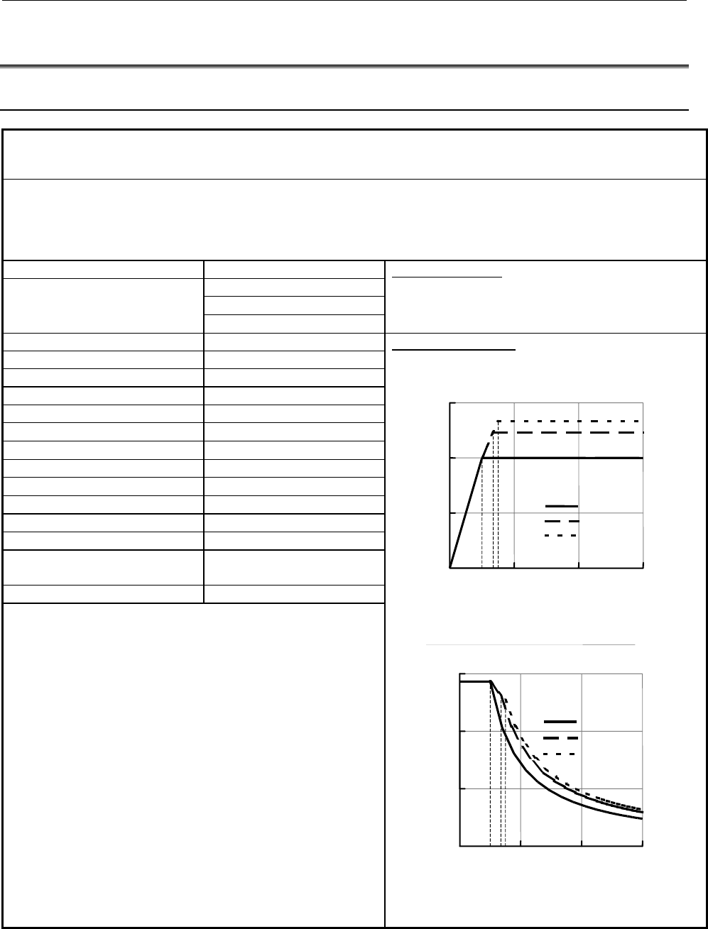
Model: BiS160L4/6000
A06B-1854-B141#0P4A
Amplifier A06B-6122-H045#H553 (αiSP-45HV Type B)
Sub module A06B-6111-H403 (SSM-100)
O-ring Kit A06B-1850-K002
Sensor α
iBZ, αiCZ (*) Check the permissible speed of the sensor.
Amplifier Input 460 V
Max. 430 V
Max. 100 A
Motor input
Rated 77 A
PSM selection data
* These values are not guaranteed output.
Maximum Power 60 kW
Constant Power 30 kW
Mass of Stator 50 kg Output characteristics
Mass of Rotor 16 kg
Rotor moment of Inertia 0.080 kgm
2
Cooling Power More than 6 kW
Cooling medium flow rate More than 10 L/min
Temperature of medium inlet
20 ℃
The rise of outlet from inlet 18 K
Density of medium 0.88 g/cm
3
Specific heat 1.78 J/gK
Thermal class F
Degree of protection Main body IP00 (*2)
Built-in Must be minimum IP54
Allowable angular acceleration
and deceleration (*1)
A06B-1854-B141 7100 rad/sec
2
(*1)Danger :
In any conditions, the angular acceleration (deceleration) of the
spindle must never exceed this value. The excess
acceleration(deceleration) might cause a slip of the rotor, and in
the worst case, there is some possibility being uncontrollable
state because of the loss of pole position.
If some accident is happen, such as the crash of spindle etc., the
motor never been restarted without running a pole position
detecting function.
(*2)Notice :
The stator is IP00 itself. The protection class of the stator
housing must be IP54 or more. Even if the stator is resin molded,
the performance for environment is same as non molded motor.
1500
1000
Power
0
15
30
45
0 2000 4000 6000
min
-
1
kW
S1 Cont.
S2 5min.
S3 15%
1350
1500
37kW S2 5min
40kW S3 15%
30kW S1 cont.
Torque
286.5
0
100
200
300
0 2000 4000 6000
min
-
1
Nm
S1 Cont.
S2 5min.
S3 15%
(*) The S3 is valid for 3 min. duty cycle.
1000
1350
(*) The S3 is valid for 3 min. duty cycle.
Contents Summary of Fanuc Synchronous Built-In Spindle Motor BiS Series Descriptions
- Page 1FANUC SY NCHRONOUS BUILT-IN SPINDLE MOTOR B*S series DESCRIPTIONS B-65342EN/01�
- Page 2FOR USERS Before getting started Be sure to read this manual thoroughly before using FANUC SYNCHRONOUS BUILT-IN SPINDLE MOTOR BiS series. It contains many important items. Do not try operation not described in this manual without permission. Otherwise, your motor may get into trouble. If it is unavo
- Page 3B-65342EN/01 SAFETY PRECAUTIONS SAFETY PRECAUTIONS This "Safety Precautions" section describes the precautions which must be observed to ensure safety when using FANUC synchronous built-in spindle motors. Users of any motor model are requested to read this manual carefully before using the synchrono
- Page 4SAFETY PRECAUTIONS B-65342EN/01 DEFINITION OF WARNING, CAUTION, AND NOTE This manual includes safety precautions for protecting the user and preventing damage to the machine. Precautions are classified into Warning and Caution according to their bearing on safety. Also, supplementary information is
- Page 5B-65342EN/01 SAFETY PRECAUTIONS WARNING WARNING - Wear the appropriate protectors and clothes when you handle the motor Wear safety shoes or gloves when handling a motor as you may get hurt on any edge or protrusion on it or electric shocks. - Keep the rotor away from the person who has medical mach
- Page 6SAFETY PRECAUTIONS B-65342EN/01 - The rotor rushes into the stator, when assembling rotor into spindle When you insert the rotor in the spindle, the rotor will suddenly rush into the stator bore by magnetic force. So, be careful enough not to sandwich your hands, etc. Do not stand on an axial extens
- Page 7B-65342EN/01 SAFETY PRECAUTIONS - Do not touch the terminals, power leads, etc., without checking voltage Even if the power line is turned off, the high voltage is still alive on the power lines for a few minutes. So, do not touch those power line parts without voltage check. - When the motor is run
- Page 8SAFETY PRECAUTIONS B-65342EN/01 CAUTION CAUTION - A magnetic card, magnetic media, computer, etc. should be kept away from the rotor An electric or magnetic equipments, such as camera, cellular phone, magnetic card, etc. might be broken by the leakage flux of the rotor. - Do not touch the running mo
- Page 9B-65342EN/01 SAFETY PRECAUTIONS - Do not drive BiS series without amplifier Applying a power source voltage directly to a motor may burn its windings. Use a specified amplifier to drive BiS series. s-7�
- Page 10SAFETY PRECAUTIONS B-65342EN/01 NOTE NOTE - Do not put on anything nor step on a motor If done, scratches and deformations may be caused. Do not pile up a motor without in package. - Avoid moisture and condensing at the temperature of 0 to 40ºC for the safekeeping If a motor is stored in a bad envir
- Page 11B-65342EN/01 SAFETY PRECAUTIONS - Perform periodic maintenance and inspection to the motor Check the winding resistance and insulation resistance periodically. Clean around the motor periodically. However the excess inspections, such as a dielectric test, an insulation test, may damage its winding.
- Page 12
- Page 13B-65342EN/01 TABLE OF CONTENTS TABLE OF CONTENTS SAFETY PRECAUTIONS............................................................................s-1 DEFINITION OF WARNING, CAUTION, AND NOTE ............................................. s-2 WARNING ......................................................
- Page 14TABLE OF CONTENTS B-65342EN/01 2.3 THE WAY TO ASSEMBLE THE SPINDLE.................................................. 28 2.4 GROUNDING A MOTOR............................................................................. 29 2.5 CABLE CONNECTION (OUTLINE) ...............................................
- Page 15B-65342EN/01 SPECIFICATIONS 1.SPECIFICATIONS 1 SPECIFICATIONS 1.1 132 FRAME .................................................................................3 1.1.1 132 Frame Specifications .................................................3 1.1.2 132 Frame Stator Dimensions .........................
- Page 161.SPECIFICATIONS SPECIFICATIONS B-65342EN/01 Order No. The explanations of Order No. A06B-18□□-B□□□#□□□□ The type of rotor and stator. Stands for the output type. The scope of supply The parts that are supplied by the order no. are the following three items. • Stator • Rotor (with 2 side rings) • Na
- Page 17B-65342EN/01 SPECIFICATIONS 1.SPECIFICATIONS 1.1 132 FRAME 1.1.1 132 Frame Specifications Model: BiS132L2/6000 A06B-1842-B141#0P4A Amplifier A06B-6122-H045#H553 (αiSP-45HV Type B) Sub module A06B-6111-H403 (SSM-100) O-Ring Kit A06B-1840-K002 Sensor αiBZ, αiCZ (*) Check the permissible speed of the s
- Page 181.SPECIFICATIONS SPECIFICATIONS B-65342EN/01 Model: BiS132L3/6000 A06B-1843-B141#0P4B Amplifier A06B-6122-H045#H553 (αiSP-45HV Type B) Sub module A06B-6111-H403 (SSM-100) O-Ring Kit A06B-1840-K002 Sensor αiBZ, αiCZ (*) Check the permissible speed of the sensor. Amplifier Input 460 V PSM selection da
- Page 19B-65342EN/01 SPECIFICATIONS 1.SPECIFICATIONS 1.1.2 132 Frame Stator Dimensions -5-�
- Page 201.SPECIFICATIONS SPECIFICATIONS B-65342EN/01 1.1.3 132 Frame Rotor Dimensions -6-�
- Page 21B-65342EN/01 SPECIFICATIONS 1.SPECIFICATIONS 1.1.4 132 Frame Assembly Installation position dimensions in rotor, stator and your shaft housing seem to become follows. -7-�
- Page 221.SPECIFICATIONS SPECIFICATIONS B-65342EN/01 1.2 160 FRAME 1.2.1 160 Frame Specifications Model: BiS160L4/6000 A06B-1854-B141#0P4A Amplifier A06B-6122-H045#H553 (αiSP-45HV Type B) Sub module A06B-6111-H403 (SSM-100) O-ring Kit A06B-1850-K002 Sensor αiBZ, αiCZ (*) Check the permissible speed of the s
- Page 23B-65342EN/01 SPECIFICATIONS 1.SPECIFICATIONS Model: BiS160L6/6000 A06B-1856-B141#0P4A Amplifier A06B-6122-H045#H553 (αiSP-45HV Type B) Sub module A06B-6111-H403 (SSM-100) O-ring Kit A06B-1850-K002 Sensor αiBZ, αiCZ (*) Check the permissible speed of the sensor. Amplifier Input 460 V PSM selection da
- Page 241.SPECIFICATIONS SPECIFICATIONS B-65342EN/01 1.2.2 160 Frame Stator Dimensions - 10 -�
- Page 25B-65342EN/01 SPECIFICATIONS 1.SPECIFICATIONS 1.2.3 160 Frame Rotor Dimensions - 11 -�
- Page 261.SPECIFICATIONS SPECIFICATIONS B-65342EN/01 1.2.4 160 Frame Assembly - 12 -�
- Page 27B-65342EN/01 SPECIFICATIONS 1.SPECIFICATIONS 1.3 SUB MODULE SM To drive BiS series, it is necessary to connect a Sub module SM(SSM) between motor and amplifier for safety and machine protection. Synchronous motor has permanent magnets inside of the rotor. So, if the motor runs freely by its inertia
- Page 281.SPECIFICATIONS SPECIFICATIONS B-65342EN/01 1.3.1 Type No. Model Type No. SSM-100 A06B-6111-H403 SSM-200 A06B-6111-H404 1.3.2 SSM Dimensions The dimensions of SSM-100 ,SSM-200 are same, and following. The view of with yellow safety cover. (This cover is fasten on the main body with 2-M4.) 55 55 7 U
- Page 29B-65342EN/01 SPECIFICATIONS 1.SPECIFICATIONS 1.4 O-RING 1.4.1 Notes • O-Ring is expendable parts O-Ring is expendable parts. So, check the O-rings periodically. If leakage is found out, change the O-ring immedeately. The period of O-ring’s life is widley changed by the cooling medium or motor’s oper
- Page 301.SPECIFICATIONS SPECIFICATIONS B-65342EN/01 1.4.3 Installation • The grooves to fit Fit O-rings on the 4-grooves indicated in the drawing below. • Drain The middle grooves of each side are for drains. They should be coincided with drain holes on outer sleeve. The actual positions are shown in the d
- Page 31B-65342EN/01 2.SPINDLE DESIGNING AND MOTOR MOUNTING 2 SPINDLE DESIGNING AND MOTOR MOUNTING 2.1 INFORMATION AND INSTRUCTION ...................................18 2.1.1 Safety Information..........................................................18 2.1.2 Protection Class................................
- Page 322.SPINDLE DESIGNING AND MOTOR MOUNTING B-65342EN/01 2.1 INFORMATION AND INSTRUCTION 2.1.1 Safety Information Do not machine to motor parts Do not machine motor parts such as the stator, rotor, and ring by yourself. Other wise, the necessary strength or accuracy cannot be achieved, causing a malfunct
- Page 33B-65342EN/01 2.SPINDLE DESIGNING AND MOTOR MOUNTING Dry condition BiS series is an electric component. It may be damaged by liquid like water and oil. Therefore keep away from them. If the air is supplied into a spindle, take some structure not to catch condensed dew. Even if the air is dried, dew c
- Page 342.SPINDLE DESIGNING AND MOTOR MOUNTING B-65342EN/01 Insulation between winding and frame Measure at 500VDC with mega-ohm tester. And judge according to following. Insulation resistance Judgment Over 100 MΩ Good No problem in normal use. But check the 10 to 100 MΩ insulation on regular intervals. Spe
- Page 35B-65342EN/01 2.SPINDLE DESIGNING AND MOTOR MOUNTING 2.1.2 Protection Class (foreign matter and liquid protection) Protection class of BiS series is IP00 when the delivery. Protection class of motor part in the spindle must be IP54 or more, and the part of drain must be IP44 or more. (Refer to the IE
- Page 362.SPINDLE DESIGNING AND MOTOR MOUNTING B-65342EN/01 2.1.3 Insulation Clearance Clearance between windings and other conductive materials have to be 3mm or more, and this condition have to be applied for all directions of windings. Refer to IEC664-1 for more details. If a motor is mold type, the clea
- Page 37B-65342EN/01 2.SPINDLE DESIGNING AND MOTOR MOUNTING 2.1.4 Conform Standards Note on assembly When installing BiS series on a machine, satisfy Article 19 of IEC60204-1. For details, refer to the standard. IEC60204-1(excerpts) 19 Tests and verification 19.1 General This standard specifies general requ
- Page 382.SPINDLE DESIGNING AND MOTOR MOUNTING B-65342EN/01 2.1.5 Deviation Axial deviation of stator and rotor Axial deviation between the center of stator core and the center of rotor core must be less than 1mm. Over 1mm deviation causes reduction of output power. less than 1mm Center of rotor core Center
- Page 39B-65342EN/01 2.SPINDLE DESIGNING AND MOTOR MOUNTING 2.2 SHRINKING THE ROTOR 2.2.1 Safety Information • The outline flow for process is shown below. Shaft Rotor, Side ring Shrink fit a rotor Finish machining Balancing spindle Assemble into the spindle • The way to fix a rotor on the spindle must be s
- Page 402.SPINDLE DESIGNING AND MOTOR MOUNTING B-65342EN/01 • All the rotor are checked its unbalance in production process. So normally, it is unnecessary to balance for the rotor after shrinkage fit, only to balance the whole main shaft. If user needs more precise balancing of the rotor, the taps on the s
- Page 412.2.2 1. Preheating rotor and ring, and refrigerating shaft 2. Shrinking fit B-65342EN/01 • Preheat rotor and ring to 140°C-150°C. Cool the shaft less than 0°C. • Mount the ring, rotor, ring, quickly and without a break. • The rotor temperature must be measured directly, and the maximum temperature
- Page 422.SPINDLE DESIGNING AND MOTOR MOUNTING B-65342EN/01 2.3 THE WAY TO ASSEMBLE THE SPINDLE Please assemble the spindle, according to following information. WARNING 1 Please be careful to magnetic force on rotor surface. Rotor has very strong magnets inside. Please take great care not to bring rotor clo
- Page 43B-65342EN/01 2.SPINDLE DESIGNING AND MOTOR MOUNTING 2.4 GROUNDING A MOTOR For safety, ground the parts which is conductive to stator core, such as jacket, surely. Refer to the following. The following shows an example of a CE marking conformity. Where to Ground On the part which is conductive to sta
- Page 442.SPINDLE DESIGNING AND MOTOR MOUNTING B-65342EN/01 2.5 CABLE CONNECTION (OUTLINE) For details, refer to the latest Descriptions (B-65282EN) of FANUC SERVO AMPLIFIER αi series. αiSP TYPE B JYA2 Synchronous Spindle Motor Control Cable JYA4 TB2 or CZ2 branch Terminal Connect external αiBZ sensor , if
- Page 45B-65342EN/01 3.PARAMETER 3 PARAMETER The parameters for BiS132L2 will be printed from next edition. - 31 -�
- Page 463.PARAMETER B-65342EN/01 3.1 132 FRAME Motor model: BiS132L3/6000 Output specification: #0P4B Amplifier αiSP-45HV Number of poles 8-pole (4 pairs) Soft version After 9D53/B Power source voltage 460V SSM SSM-100 Parameter No. Setting value NOTE 15i 16i 1 Connect SSM without exceptions. 3006 4006 0000
- Page 47B-65342EN/01 3.PARAMETER 3.2 160 FRAME Motor model: BiS160L4/6000 Output specification: #0P4A Amplifier αiSP-45HV Number of poles 8-pole (4 pairs) Soft version After 9D53/B Power source voltage 460V SSM SSM-100 Parameter No. Setting value NOTE 15i 16i 1 Connect SSM without exceptions. 3006 4006 0000
- Page 483.PARAMETER B-65342EN/01 Motor model: BiS160L6/6000 Output specification: #0P4A Amplifier αiSP-45HV Number of poles 8-pole (4 pairs) Soft version After 9D53/B Power source voltage 460V SSM SSM-100 Parameter No. Setting value NOTE 15i 16i 1 Connect SSM without exceptions. 3006 4006 0000 0000 3007 400
- Page 49B-65342EN/01 INDEX INDEX SHRINKING THE ROTOR............................................25
SPECIFICATIONS ...........................................................1 132 FRAME ................................................................ 3, 32 SPINDLE DESIGNING AND MOTOR MOUNTING...17 1 - Page 50
- Page 51Revision Record FANUC SYNCHRONOUS BUILT-IN SPINDLE MOTOR BiS series DESCRIPTIONS (B-65342EN) 01 Aug., 2005 Edition Date Contents Edition Date Contents�
- Page 52
- Page 53TECHNICAL REPORT (MANUAL) NO.TMS 05/052E Date November 15 2005 General Manager of Servo Laboratory Correctional information for the manual B-65342EN/01 of FANUC SYNCHRONOUS BUILT-IN SPINDLE MOTOR BiS series 1.Communicate this report to: Your information only ○ GE Fanuc-N, GE Fanuc-E FANUC Robotics C
- Page 54Correctional information for the manual B-65342EN/01 of FANUC SYNCHRONOUS BUILT-IN SPINDLE MOTOR BiS series 1. Type of applied technical documents Name FANUC SYNCHRONOUS BUILT-IN SPINDLE MOTOR BiS series DESCRIPTIONS Spec.No./Version B-65342EN/01 2. Summary of change Group Name / Outline New, Add, A
- Page 55This document provides the corrective information for the manual B-65342EN/01 of FANUC SYNCHRONOUS BUILT-IN SPINDLE MOTOR BiS series. The pages of 10, 11, 12 in the manual, although these pages are the 160 frame section, the drawings of 132 frame is printed by some trouble. This document provides th
- Page 561.2.2 160 Frame Stator Dimensions TITLE Correctional information for the manual of BiS series DRAW. NO. CUST. 01 051111 seki first edition B-65342EN/01-2 SHEET EDIT. DATE DESIG. DESCRIPTION FANUC LTD 3 /05�
- Page 571.2.3 160 Frame Rotor Dimensions TITLE Correctional information for the manual of BiS series DRAW. NO. CUST. 01 051111 seki first edition B-65342EN/01-2 SHEET EDIT. DATE DESIG. DESCRIPTION FANUC LTD /05�
- Page 581.2.4 160 Frame Assembly TITLE Correctional information for the manual of BiS series DRAW. NO. CUST. 01 051111 seki first edition B-65342EN/01-2 EDIT. DATE DESIG. DESCRIPTION FANUC LTD SHEET 5 /05�
- Page 59TECHNICAL REPORT (MANUAL) NO.TMS 05/ E Date October 14 2005 General Manager of Servo Laboratory Additional information in shrink fitting of a rotor of SYNCHRONOUS BUILT-IN SPINDLE MOTOR BiS series 1.Communicate this report to: Your information only ○ GE Fanuc-N, GE Fanuc-E FANUC Robotics CINCINNATI
- Page 60Additional information in shrink fitting of a rotor of SYNCHRONOUS BUILT-IN SPINDLE MOTOR BiS series 1. Type of applied technical documents Name FANUC SYNCHRONOUS BUILT-IN SPINDLE MOTOR BiS series DESCRIPTIONS Spec.No./Version B-65342EN/01 2. Summary of change Group Name / Outline New, Add, Applicab
- Page 61This document provides the additional information to the DISCRIPTIONS of FANUC BUILT-IN SPINDLE MOTOR BiS series in shrink fitting. The shrink fitting process described in the DISCRIPTIONS(B-65342EN) is suitable for the smaller rotor and is unsuitable for the heavy rotor on safety point. The shrink
- Page 62(Shrink fitting operation) - The procedure of shrink fitting is shown in the drawing next sheet. - The recommended material for jigs are followings - Aluminium alloy - MC nylon (the type of 150 degree Celsius proof ) - Fluoric synthetic resin (the type of 150 degree Celsius proof ) ,e.g. PTFE TITLE
- Page 63TITLE Additional information in shrink fitting of a rotor of BiS series DRAW. NO. CUST. 01 051013 arimatu first edition B-65342EN/01-1 SHEET EDIT. DATE DESIG. DESCRIPTION FANUC LTD 4 /04�