Series 30i-MODEL A, Tool management extension function Additional Manual Page 15
Additional Manual
A-79345E
Title
Draw
No.
Ed. Date Design Description
Date Jan.06.’04 Design. Apprv.
13/27
page
FANUC Series 30i-MODEL A
Tool management extension function
Setting of spindle position/standby position display
In MG on the tool management data screen, a spindle position or standby position is
displayed as a number such as 11, 12, and 13. With the spindle position/standby position
display setting function, three arbitrary characters can be displayed using the G10 format.
Format
Format
G10L77P4; Set spindle position/standby position display
N_;
P_R_;
G11; Cancel the setting mode
Description of symbols
N_:Spindle position/standby position setting
P_:Character number (1 to 3)
R_:Character code (ANK or Shift JIS)
Explanation
・ Spindle position/standby position setting (N_)
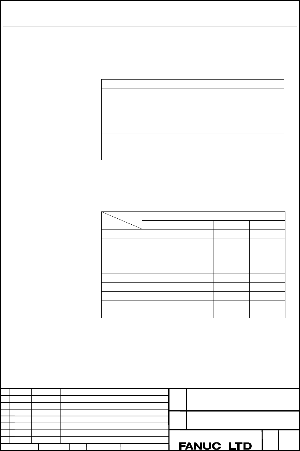
Specify a spindle position or standby position to be renamed. The table below indicates the
values to be specified.
Spindle position
First Second Third Fourth
1st path 111 112 113 114
2nd path 211 212 213 214
3rd path 311 312 313 314
4th path 411 412 413 414
5th path 511 512 513 514
6th path 611 612 613 614
7th path 711 712 713 714
8th path 811 812 813 814
9th path 911 912 913 914
10th path 1011 1012 1013 1014
Contents Summary of Series 30i-MODEL A, Tool management extension function Additional Manual
- Page 1TECHNICAL REPORT NO. TMN 04/020E Date :Mar .30, 2004 General Manager of Software Laboratory FANUC Series 30i-A Newly additional functions 1. Communicate this report to: Your information only GE Fanuc-N, GE Fanuc-E FANUC Robotics MILACRON Machine tool builder Sales agency End user 2. Summary for Sale
- Page 2FANUC Series30i –A newly additional functions Drawing number Functions 1 A-79227E External Data Input 2 A-79226E One Touch Macro call 3 A-79196E Temporary absolute coordinate setting 4 A-79354E System alarm 5 A-79349E Touch Panel Control 6 A-79253E Distance coded linear scale interface 7 A-79364E Li
- Page 3FANUC Series 30i-MODEL A Tool management extension function Specifications FANUC Series 30i-MODEL A Title Tool management extension function Draw A-79345E No. Ed. Date Design Description page 1/27 Date Jan.06.’04 Design. Apprv.
- Page 4Overview The following functions have been added to the tool management function: 1. Customization of tool management data display 2. Setting of spindle position/standby position display 3. Input of customize data with the decimal point 4. Protection of various tool information items with the KEY si
- Page 5Customization of tool management data display With the tool management data screen display customization function, the display positions of screen elements (type number, tool information, life counter, and so forth) on the tool management screen can be changed and whether to display or hide such scr
- Page 6・ Tool management data screen display position number (N_) Specify a display position number on the tool management data screen. ・ A display position number represents an ordinal number from the leftmost position on the tool management data screen. ・ As N, a number from 1 to 200 can be specified. ・T
- Page 7・Items common to machining center systems and lathe systems R Item Display Remarks width -1 End of setting - 0 Blank column 10 1 No. 4 For spindle/standby positions for 10 paths 2 TYPE-NO. 8 3 MG 4 4 POT 5 5 T-INFORMATION 10 6 L-COUNT 10 7 MAX-LIFE 10 8 NOTICE-L 10 The display width is switched by 9
- Page 8・Offset-related items for lathe systems R Item Display Remarks width 40 TG(Tool geometry 4 compensation number) 41 TW(Tool wear 4 compensation number) 42 OFFSET-X 10 43 OFFSET-Z 10 44 OFFSET-R 10 Tool nose radius compensation 45 TIP 10 46 OFFSET-Y 10 Y-axis offset 47 OFFSET-B 10 B-axis control 48 GE
- Page 9・Items related to customize data R Item Display Remarks width 80 CUSTOM 0 10 81 CUSTOM 1 10 82 CUSTOM 2 10 83 CUSTOM 3 10 84 CUSTOM 4 10 85 CUSTOM 5 10 Tool management function 86 CUSTOM 6 10 customize data extension (5 to 87 CUSTOM 7 10 20) or tool management function 88 CUSTOM 8 10 customize data
- Page 10R Item Display Remarks width 116 CUSTOM 36 10 117 CUSTOM 37 10 118 CUSTOM 38 10 119 CUSTOM 39 10 120 CUSTOM 40 10 NOTE ・ If G10 L77 P3 is terminated normally, the power must be turned off before operation is continued. ・ The setting becomes effective after the power is turned off then back on. Examp
- Page 11Example 1: Page 1 Example 1: Page 2 FANUC Series 30i-MODEL A Title Tool management extension function Draw A-79345E No. Ed. Date Design Description page 9/27 Date Jan.06.’04 Design. Apprv.
- Page 122. Example of setting tool offset memory A G10L77P3; Set tool management data screen display customization N1 R1; Set No. as number 1 N2 R2; Set TYPE-NO. as number 2 N3 R3; Set MG as number 3 N4 R4; Set POT as number 4 N5 R5; Set T-INFORMATION as number 5 N6 R6; Set L-COUNT as number 6 N7 R7; Set MA
- Page 13Example 2: Page 1 Example 2: Page 2 FANUC Series 30i-MODEL A Title Tool management extension function Draw A-79345E No. Ed. Date Design Description page 11/27 Date Jan.06.’04 Design. Apprv.
- Page 143. When G10 is set again (Before re-registration) G10L77P3; Set tool management data screen display customization N1 R1; Set No. as number 1 N2 R2; Set TYPE-NO. as number 2 N3 R3; Set MG as number 3 N4 R4; Set POT as number 4 N5 R-1; End G11; Cancel the setting mode (Re-registration) G10L77P3; Set t
- Page 15Setting of spindle position/standby position display In MG on the tool management data screen, a spindle position or standby position is displayed as a number such as 11, 12, and 13. With the spindle position/standby position display setting function, three arbitrary characters can be displayed usin
- Page 16Standby position First Second Third Fourth 1st path 121 122 123 124 2nd path 221 222 223 224 3rd path 321 322 323 324 4th path 421 422 423 424 5th path 521 522 523 524 6th path 621 622 623 624 7th path 721 722 723 724 8th path 821 822 823 824 9th path 921 922 923 924 10th path 1021 1022 1023 1024 ・
- Page 17Example 1. When spindle 1 is named "SP1", and standby 1 is named "WT1" G10L77P4; Set spindle position/standby position N111; Specify spindle 1 P1 R83; 53h as ASCII code for "S" P2 R80; 50h as ASCII code for "P" P3 R49; 31h as ASCII code for "1" N121; Specify standby 1 P1 R87; 57h as ASCII code for "
- Page 18Input of customize data with the decimal point With the function for input of customize data with the decimal point, the number of decimal places can be set using the G10 format for each customize data item (customize data 1, ..., 40) to enable data input with the decimal point. Format Format G10L77
- Page 19Example 1. When customize data 1 and customize data 2 are input with three decimal places G10L77P5; Set the number of decimal places for customize data N1 R3; Set the number of decimal places to 3 for customize data 1 N2 R3; Set the number of decimal places to 3 for customize data 2 G11; Cancel the
- Page 20Protection of various tool information items with the KEY signal When tool management data is in the edit state, various information items can be modified. By setting bit 0 of parameter No. 13204 to 1, tool management data can be protected with the KEY signal so that various information items are no
- Page 21Selection of a tool life count period A tool life count period can be chosen between 1 sec and 8 msec on a tool-by-tool basis. Tool life count period selection Bit 5 of tool information is used to make a life count period selection. Item Description Data length 1 byte (flag data) #5 REV 0:A life cou
- Page 22Input to and output from an external device Input to and output from an external device is enabled only on the ALL IO screen, the tool management screen, or the cartridge screen. ・Input/output using the ALL IO screen By pressing the [ALL I/O] soft key on the
screen, ALL IO screen is display - Page 23System variables The following tool management data of the tool being used as a spindle after a tool change by M06 and the tool to be used next that is specified by a T code can be read through custom macro variables. The custom macro variables are read-only variables. Being used Item #8401 Data num
- Page 24Being used Item #8449 Customize data 19 #8450 Customize data 20 #8451 Customize data 21 #8452 Customize data 22 #8453 Customize data 23 #8454 Customize data 24 #8455 Customize data 25 #8456 Customize data 26 #8457 Customize data 27 #8458 Customize data 28 #8459 Customize data 29 #8460 Customize data
- Page 25G10L77P5; ① Set customize data decimal point position N1 R3; ② Set 3 as decimal point position of customize data 1 N2 R1; ③ Set 1 as decimal point position of customize data 2 G11; ④ Cancel the setting mode ; G10 L75 P1; ⑤ Register tool management data N01; ⑥ Register with No. 1 P1 R12345; ⑦ Set ”12
- Page 26In Example 2, customize data 1 is directly set in customize data 2 by using a custom macro variable. Customize data 1 holds "12.345". In step ⑧, the data is multiplied by 1000 to eliminate the fractional part. So, this command is equivalent to "P2 R12345", so that "1234.5" is set in customize data 2
- Page 27Parameter #7 #6 #5 #4 #3 #2 #1 #0 13201 TDB TDC [Input type] Parameter input [Data type] Bit system common type NOTE When this parameter is set, the power must be turned off before operation is continued. #0 TDC The tool management data screen customization function of the tool management function i
- Page 281.1 ALARM Alarm message Number Message Description 5312 ILLEGAL COMMAND IN In commands from G10 L75/L76/L77 to G10 L75/76/77 G11, there is a format error, or a value beyond the specifiable range is specified. Correct the program. Warning message Warning message Description INPUT IS REJECTED When the
- Page 291.2 Notes This function is optional function. FANUC Series 30i-MODEL A Title Tool management extension function Draw A-79345E No. Ed. Date Design Description page 27/27 Date Jan.06.’04 Design. Apprv.