Fanuc Laser C Series Improved Mirror Stage Additional Manual Page 2
Additional Manual
FANUC LASER C series
Improved Mirror Stage
FANUC LASER C series
Improved Mirror Stage
1. Outline
In laser C1000-E, C2000-E, C4000-E, the improvement design of the mirror stage was
done for the improvement of reliability and maintainability. Because the distortion
when the mirror is mounted by this improvement design decreases, the reproducibility
of the beam mode when you exchanges the mirror, and the mirror is cleaned improves
and shortening the mirror adjustment time can be expected.
2. The change content is detailed.
The mirror stage processed to the output coupler mount and the rear mirror mount in
high accuracy was adopted, and a mirror base was deleted.
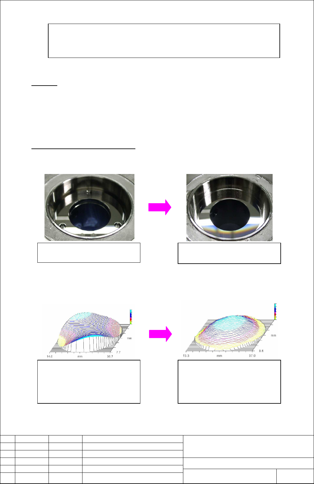
Before
(With "Mirror Base")
After
(Surface high accuracy
processed)
The mirror hits to a personally precise mirror stage without the mirror base and is
mounted. Therefore, the distortion of the mirror when the mirror is mounted is greatly
decreased.
Before
The distortion occurs in the mirro
r
because of the difference of the
accuracy of surface of mirror touched.
(Mirror geometry observation with ZYGO
interferometer)
A
fte
r
The distortion of the mirror decreases
by improving surface of mirro
r
touched accuracy.
(Mirror geometry observation with ZYGO
interferometer)
1/4
FANUC LTD
A-81053E-037
Description Design Date Edit.
01 021007 MURAKAMI
title
Sheet
Draw. No.
MURAKAMI
03 030303 MURAKAMI Add C1000-E, C2000-E at P1∼P4 M. Maed
a
Changed P2, P3
M. Maed
a
02 030127
M. Maed
a
Contents Summary of Fanuc Laser C Series Improved Mirror Stage Additional Manual
- Page 1TECHNICAL REPORT(MANUAL) NO. TML 03/003E Date 24 June, 2003 General Manager of Laser Laboratory The modification for improvement of reliability and maintainability 1. Communicate this report to: ○ Your information only ○ GE Fanuc-N, GE Fanuc-E FANUC Robotics MILACRON ○ Machine tool builder Sales age
- Page 2FANUC LASER C series Improved Mirror Stage 1. Outline In laser C1000-E, C2000-E, C4000-E, the improvement design of the mirror stage was done for the improvement of reliability and maintainability. Because the distortion when the mirror is mounted by this improvement design decreases, the reproducib
- Page 33. Stage block diagram Mirror base Stage This is deleted by the improvement design at this time. O.C., R.M. O-ring Mirror holder O-ring Mirror support Screw It is as usual and there is no change. (There is interchangeability) 4. About the method of maintaining a output coupler and a rear mirror It i
- Page 46-1-2. C4000-E When the Cavity mirrors is specified with A98L-0001-0756 (OC), A98L-0001-0757/B (RM). ITEM Name Old spec. Q'ty New spec. Q'ty STAGE STAGE A290-4540-V161 1 A290-4540-V163#C1 1 (for Output Coupler) A290-4540-V151 A290-4540-V153#C1 FITTING (attached) - A97L-0200-0648#L-2A-B 1 FITTING (at
- Page 57. Identification of oscillator improvement applied In oscillator to which the above-mentioned improvement design is applied, the sticker of the figure below has been added in the panel. Detail of additional sticker (CE mark) Additional sticker Name plate Sticker putting position 8. Application Appl