Tool axis compensation in tool axis direction Additional Manual Page 10
Additional Manual
Title
No.
FANUC Series 16i-MA/MB
Tool axis compensation in tool axis direction
A-78437E
Page
9/24
Newly registered
Ver Date Design Description
01 01.03.16
Hosokawa
1.1 Control Point Compensation of Tool Length Compensation in Tool Axis Direction
Normally, the control point of tool length compensation in tool axis direction is the point
of intersection of the centers of two rotation axes. The machine coordinates also indicate
this control point.
This section explains the compensation performed when the centers of the two rotation
axes do not intersect and also explains how to place the control point at a convenient
position on the machine.
Description
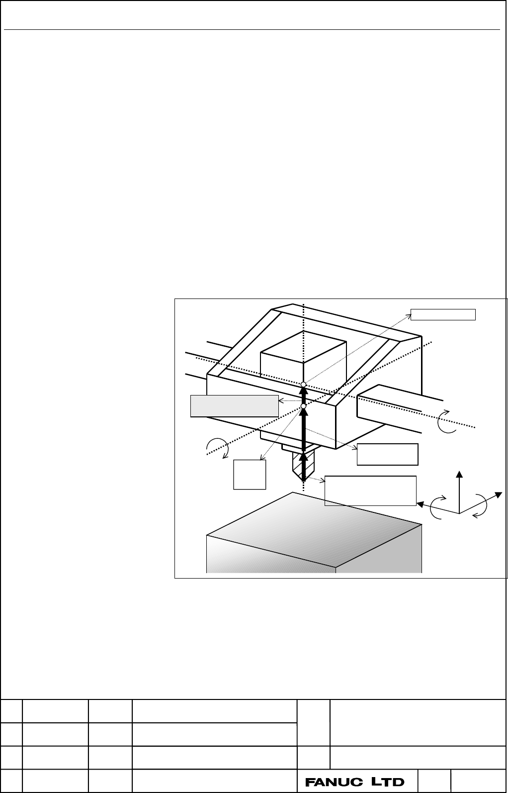
- Compensation of the rotation centers of two rotation axes
Compensation when the rotation centers of two rotation axes do not match is performed.
The length from the tool mounting position to the first rotation axis center is set as the
tool holder offset value in parameter No. 19666.
The vector from the first rotation axis center to the second rotation axis center is set as the
rotation center compensation vector in parameter No. 19661. Since parameter No. 19661
is an axis type parameter, the compensation amount for three axes (X, Y, and Z) can be
set in this parameter.
Workpiece
Tool length
compensation amount
Tool holder
offset
Rotation center
compensation vector
A axis
center
B axis center
B
A
Z
Y
X
B
A
Fig. 1.1 (a) Compensation of Rotation Centers of Two Rotation Axes
Contents Summary of Tool axis compensation in tool axis direction Additional Manual
- Page 1TECHNICAL REPORT (MANUAL) No.TMN 01/048 Date : Mar. 29, 2001 General Manager of Software Laboratory FANUC Series 16i-MA/MB Tool Axis Compensation In Tool Axis Direction 1. Communicate this report to: Your information only ○ GE Fanuc-N, GE Fanuc-E FANUC Robotics MILACRON ○ Machine tool builder Sales
- Page 2FANUC Series 16i-MA/MB Tool axis compensation in tool axis direction This specification may be modified for improvement without notice. FANUC Series 16i-MA/MB Title Tool axis compensation in tool axis direction 01 01.03.16 Hosokawa Newly registered No. A-78437E Ver Date Design Description Page 1/24
- Page 3Contents 1 TOOL LENGTH COMPENSATION IN TOOL AXIS DIRECTION............................................................ 3 Format ......................................................................................................................................................................... 3
- Page 41 TOOL LENGTH COMPENSATION IN TOOL AXIS DIRECTION General When a 5-axis machine that has two axes for rotating the tool is used, tool length compensation can be performed in a specified tool axis direction on a rotation axis. When a rotation axis is specified in tool length compensation in tool axis
- Page 5- Examples of machine configuration and rotation axis calculation formats Let Vx, Vy, Vz, Lc, a, b, and c be as follows : Vx,Vy,Vz : Tool compensation vectors along the X-axis, Y- axis, and Z-axis Lc : Offset value a,b,c : Absolute coordinates on the A-axis, B-axis and C- axis Then, the tool compens
- Page 6(2) B-axis and C-axis, with the tool axis on the Z-axis B C Z Workpiece C B Y X Vx = Lc * sin(b) * cos(c) Vy = Lc * sin(b) * sin(c) Vz = Lc * cos(b) (3) A-axis and B-axis, with the tool axis on the X-axis A B Z A Workpiece X B Y Vx = Lc * cos(b) Vy = Lc * sin(b) * sin(a) Vz = -Lc * sin(b) * cos(a) F
- Page 7(4) A-axis and B-axis, with the tool axis on the Z-axis, and the B-axis used as the master B A Z B X Workpiece Y A Vx = Lc * cos(a) * sin(b) Vy = -Lc * sin(a) Vz = Lc * cos(a) * cos(b) (5) A-axis and B-axis, with the tool axis on the Z-axis, and the A-axis used as the master A B Z Y B Workpiece X A
- Page 8- Tool holder offset The machine-specific length from the rotation center of the tool rotation axes (A- and B- axes, A- and C-axes, and B- and C-axes) to the tool mounting position is referred to as the tool holder offset. Unlike a tool length offset value, a tool holder offset value is set in param
- Page 9- Rotation axis offset Set offsets relative to the rotation angles of the rotation axes in parameter No. 19659. The compensation vector calculation formula is the same as that used for rotation axis origin compensation, except that Bp and Cp are changed to rotation axis offsets. When rotation axis o
- Page 101.1 Control Point Compensation of Tool Length Compensation in Tool Axis Direction Normally, the control point of tool length compensation in tool axis direction is the point of intersection of the centers of two rotation axes. The machine coordinates also indicate this control point. This section ex
- Page 11According to the machine type, set the values listed in the following table: Table 1.1 (a) Setting the Tool Holder Offset and Rotation Center Compensation Vector Machine type Tool holder offset Rotation center Parameter No. 19666 compensation vector Parameter No. 19661 (1) A- and C- axes. Tool axis
- Page 12- Spindle center compensation Compensation of the spindle center is performed. The amount of spindle center compensation is set in parameter No. 19662. Since parameter No. 19662 is an axis type parameter, the compensation amount for three axes (X, Y, and Z) can be set in this parameter. Second rotat
- Page 13Ordinary tool length Tool length compensation in Tool length compensation in tool compensation (G43) tool axis direction(G43.1): axis direction(G43.1): When tool is not tilted When tool is tilted Control point before shift Shift vector Control Control point point Tool length compensation vector Work
- Page 14Jx, Jy, Jz :Rotation center compensation vector Cx, Cy, Cz :Spindle center compensation vector Sx, Sy, Sz:Shift vector Suppose the above. Then, the tool length compensation vector for each axis is calculated depending on the machine type, as follows: (1) A- and C-axes. The tool axis is the Z-axis. é
- Page 15Restriction - Limitation of Functions In the mode for this function, the following functions can be used, but the condition of each function cannot be changed - Inch/metric conversion The alarm is issued when the condition is changed by G20 or G21 command. - Mirror image The condition of DI signal c
- Page 16- Machine coordinate system -G53 - Single direction positioning -G60 - Automatic corner override -G62 - Tapping mode -G63 - Macro call -G65,G66,G67 (Sub program call is available) - Figure copy -G72.1,G72.2 - Canned cycles -G73-G79,G80,G81-G89,G98,G99 - Electric gear box -G80,G81 - Function for hobb
- Page 17- Thc command for the tool life management function (Tool life time is able to be counted in this mode, but the command for the tool life management function cannot be used.) - Macro executor ( Execution macro ) - Manual handle interruption operation - External deceleration External decelaration is
- Page 18Parameter #7 #6 #5 #4 #3 #2 #1 #0 19650 RAP RAM [In pu t t ype] P a r a m et er in pu t [Da t a t ype] Bit a xis #0 RAM Specifies wh et h er t o u se t h e a xis a s t h e r ot a t ion a xis for t ool len gt h compen sa t ion in t ool a xis dir ect ion . 0: Not used as the rotation axis. 1: Used as
- Page 1919656 Tool axis direction [In pu t t ype] P a r a m et er in pu t [Da t a t ype] Wor d t ype [Va lid da t a r a n ge] 1-3 Enter the tool axis direction when the two rotation axes are set at 0 degree. Data Tool axis direction 1 X-axis 2 Y-axis 3 Z-axis FANUC Series 16i-MA/MB Title Tool axis compensat
- Page 2019657 Master rotation axis number [Input type] Parameter input [Data type] wor d t ype [Valid data range] 0 - Max axes When a machine does not have the rotation axis that turns about the tool axis, the axis number of a rotation axis used as the master axis is set. For machines not using the master-a
- Page 21Data No. Data 19655 X Y Z W A B 0 0 0 0 1 2 19656 3 19657 5 19658 Angular displacement of a rotation axis [In pu t t ype] P a r a m et er in pu t [Da t a t ype] 2 wor d a xis [Un it of da t a ] degr ee in cr emen t syst em IS-A IS-B IS-C Un it Rot a t ion a xis 0.01 0.001 0.0001 deg [Min im u m u n
- Page 2219660 Origin offset value of a rotation axis [In pu t t ype] P a r a m et er in pu t [Da t a t ype] 2 wor d a xis [Un it of da t a ] degr ee in cr emen t syst em IS-A IS-B IS-C Un it Rot a t ion a xis 0.01 0.001 0.0001 deg [Min im u m u n it of da t a ] Depen d on t h e in cr em en t syst em of t h
- Page 2319662 Spindle center compensation vector in tool length compensation in tool axis direction [In pu t t ype] P a r a m et er in pu t [Da t a t ype] 2 wor d a xis [Un it of da t a ] m m, in ch (m a ch in e u n it ) in cr em en t syst em IS-A IS-B IS-C u n it Millimeter machine 0.01 0.001 0.0001 mm Inc
- Page 2419666 Tool holder offset for tool length compensation in tool axis direction [In pu t t ype] P a r a m et er in pu t [Da t a t ype] 2 wor d [Un it of da t a ] m m , in ch (m a ch in e u n it ) in cr emen t syst em IS-A IS-B IS-C u n it Millimeter machine 0.01 0.001 0.0001 mm Inch machine 0.001 0.000
- Page 25Alarm and message Number Message Contents P/S5196 ILLEGAL AXIS OPERATION A function which cannot be used during HPCC function or 5- axis control function is being executed was commanded. P/S5435 PARAMETER OUT OF RANGE (TLAC) Illegal parameter setting. (Set value is out of range.) P/S5436 PARAMTER SE