I/O Module Type-2 for Connector Panel, Connection Manual Additional Manual Page 23
Additional Manual
EDIT.
SHEET
DRAW. NO.
CUST.
TITLE
23
/
29
DESCRIPTIONDESIG.DATE
I/O module type-2 fo
r
Connector board
Connection manual
A-80950E
FANUC LTD
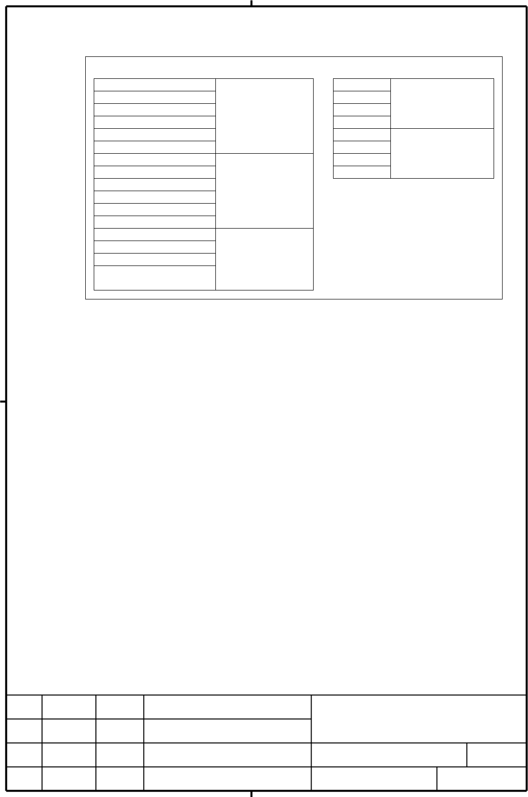
15. Address allocation
For the Connector panel I/O module , I/O addresses are mapped as follows.
I/O module type-2 is allocated a group of DI addresses(16 bytes) and a group of
DO addresses(8 bytes). Expansion module can be added or removed as required.
The reason for this address allocation is explained below.
The MPG interface (MPG counter) occupies a DI space from Xm + 12 through Xm + 14.
These address are fixed regardless of whether Expansion module is used, and Xm + 12 through
Xm + 14 must be allocated as a DI work area to enable the use of the MPG. Therefore, when
using a MPG, allocate DI addresses in units of 16 bytes. Do not use the DI space from
Xm + 12 through Xm + 14 for Ladder; the CNC process the MPG counter value directly.
DI address Xm+15 is used for detecting over current and overheating alarms that occur
in the IC used in the DO driver. This address is fixed regardless of whether Expansion
module is used, and it must be allocated as a work area before it can be used.
When using this area, therefore allocate DI addresses in unit of 16byte.
DI space map DO space map
Xm Yn
Xm + 1 Yn + 1
Xm + 2 Yn + 2
Xm + 3 Yn + 3
Basic module
Xm + 4 Yn + 4
Xm + 5
Basic module
Yn + 5
Xm + 6 Yn + 6
Xm + 7 Yn + 7
Expansion module
Xm + 8
Xm + 9
Xm + 10
Xm + 11
Expansion module
Xm + 12(for 1st MPG)
Xm + 13(for 2nd MPG)
Xm + 14(for 3rd MPG)
Xm + 15
(DO Alarm Detection)
Basic module
Contents Summary of I/O Module Type-2 for Connector Panel, Connection Manual Additional Manual
- Page 1I/O Module type-2 for Connector Panel Connection Manual - Contents - 1. Configuration 2. Connector layout diagram 3. Connection diagram 4. Module Specifications 5. Installation conditions 6. Power supply rating 7. DI/DO Connection Pin Assignment 8. DI(Input signal) Connection 9. DO(Output signal) Co
- Page 21. Configuration Connector for I/O Link interface Fuse Flat Cable for Module connection The modules are Connected directly to the connection printed circuit board. Connector for I/O Link interface Connector for Manual Pulse Generator Expansion module Basic Module Note : Basic module must be installe
- Page 32. Connector layout diagram Basic module Fuse I/O Link Connector (JD1B) Connector for the connection printed I/O Link Connector circuit board.(CB161) (JD1A) Connector for Module connection(CA101) Manual Pulse Generator Connector(JA3) Front side Rear side Expansion module Connector for Module connect
- Page 43. Connection diagram Control unit or preceding slave unit I/O Uint JD1B I/O Link JD1A(JA44) JD1B JD1A MPG JA3 CB161 MPG +24V CA101 Power supply Connector Panel MPG Flat Basic module Cable CA102 Machine side DI/DO CB161 Expansion module Note: The maximum configuration per one group on I/O Link consi
- Page 54. Module Specifications Name Drawing No. Specifications I/O module type-2 A03B-0815-C040 DI/DO=48/32 (Basic module B1) With MPG interface I/O module type-2 A03B-0815-C041 DI/DO=48/32 (Basic module B2) Without MPG interface I/O module type-2 A03B-0815-C042 DI/DO=48/32 (Expansion module E1) Fuse (acc
- Page 67. DI/DO Connection Pin Assignment Base module Expansion module CB161(HONDA MRF-96ML) CB162(HONDA MRF-96ML) A B C A B C 32 +24V +24V +24V 32 +24V +24V +24V 31 0V 0V 0V 31 0V 0V 0V 30 0V 0V 0V 30 0V 0V 0V 29 DICOM0 Xm+0.0 29 DICOM6 Xm+6.0 28 Xm+0.1 Xm+0.2 Xm+0.3 28 Xm+6.1 Xm+6.2 Xm+6.3 27 Xm+0.4 Xm+0
- Page 78. DI(Input signal) Connection Address number Bit number Pin number Xm+0.0 RV CB161(C29) Xm+0.1 RV CB161(A28) Xm+0.2 RV CB161(B28) Xm+0.3 RV CB161(C28) Xm+0.4 RV CB161(A27) Xm+0.5 RV CB161(B27) Xm+0.6 RV CB161(C27) Xm+0.7 RV CB161(A26) Xm+0.0 through Xm+0.7 are CB161(B29 DI pins for which a common D
- Page 8Address number Bit number Pin number Xm+2.0 RV CB161(A23) Xm+2.1 RV CB161(B23) Xm+2.2 RV CB161(C23) Xm+2.3 RV CB161(A22) Xm+2.4 RV CB161(B22) Xm+2.5 RV CB161(C22) Xm+2.6 RV CB161(A21) Xm+2.7 RV CB161(B21) 0V Xm+3.0 RV CB161(C21) Xm+3.1 RV CB161(A20) Xm+3.2 RV CB161(B20) Xm+3.3 RV CB161(C20) Xm+3.4 R
- Page 9Address number Bit number Pin number Xm+4.0 RV CB161(B18) Xm+4.1 RV CB161(C18) Xm+4.2 RV CB161(A17) Xm+4.3 RV CB161(B17) Xm+4.4 RV CB161(C17) Xm+4.5 RV CB161(A16) Xm+4.6 RV CB161(B16) Xm+4.7 RV CB161(C16) 0V Xm+5.0 RV CB161(A15) Xm+5.1 RV CB161(B15) Xm+5.2 RV CB161(C15) Xm+5.3 RV CB161(A14) Xm+5.4 R
- Page 10Address number Bit number Pin number Xm+6.0 RV CB162(C29) Xm+6.1 RV CB162(A28) Xm+6.2 RV CB162(B28) Xm+6.3 RV CB162(C28) Xm+6.4 RV CB162(A27) Xm+6.5 RV CB162(B27) Xm+6.6 RV CB162(C27) Xm+6.7 RV CB162(A26) Xm+6.0 through Xm+6.7 are DI pins for which a common CB162(B29) Voltage can be selected. DICOM6
- Page 11Address number Bit number Pin number Xm+8.0 RV CB162(A23) Xm+8.1 RV CB162(B23) Xm+8.2 RV CB162(C23) Xm+8.3 RV CB162(A22) Xm+8.4 RV CB162(B22) Xm+8.5 RV CB162(C22) Xm+8.6 RV CB162(A21) Xm+8.7 RV CB162(B21) 0V Xm+9.0 RV CB162(C21) Xm+9.1 RV CB162(A20) Xm+9.2 RV CB162(B20) Xm+9.3 RV CB162(C20) Xm+9.4 R
- Page 12Address number Bit number Pin number Xm+10.0 RV CB162(B18) Xm+10.1 RV CB162(C18) Xm+10.2 RV CB162(A17) Xm+10.3 RV CB162(B17) Xm+10.4 RV CB162(C17) Xm+10.5 RV CB162(A16) Xm+10.6 RV CB162(B16) Xm+10.7 RV CB162(C16) 0V Xm+11.0 RV CB162(A15) Xm+11.1 RV CB162(B15) Xm+11.2 RV CB162(C15) Xm+11.3 RV CB162(A
- Page 139. DO(Output signal) Connection Pin number DOCOM01 CB161(A01,B01) +24V 0V Address number Bit number +24V stabilized power supply Yn+0.0 CB161(C01) Realy DV Yn+0.1 DV CB161(A02) Yn+0.2 DV CB161(B02) Yn+0.3 DV CB161(C02) Yn+0.4 DV CB161(A03) Yn+0.5 DV CB161(B03) Yn+0.6 DV CB161(C03) Yn+0.7 DV CB161(A0
- Page 14Pin number DOCOM23 CB161(A07,B07) +24V 0V Address number +24V stabilized Bit number power supply Yn+2.0 CB161(C07) Realy DV Yn+2.1 DV CB161(A08) Yn+2.2 DV CB161(B08) Yn+2.3 DV CB161(C08) Yn+2.4 DV CB161(A09) Yn+2.5 DV CB161(B09) Yn+2.6 DV CB161(C09) Yn+2.7 DV CB161(A10) Yn+3.0 DV CB161(B10) Yn+3.1 D
- Page 15Pin number DOCOM45 CB162(A01,B01) +24V 0V Address number +24V stabilized Bit number power supply Yn+4.0 CB162(C01) Realy DV Yn+4.1 DV CB162(A02) Yn+4.2 DV CB162(B02) Yn+4.3 DV CB162(C02) Yn+4.4 DV CB162(A03) Yn+4.5 DV CB162(B03) Yn+4.6 DV CB162(C03) Yn+4.7 DV CB162(A04) Yn+5.0 DV CB162(B04) Yn+5.1 D
- Page 16Pin number DOCOM67 CB162(A07,B07) +24V 0V Address number Bit number +24V stabilized power supply Yn+6.0 CB162(C07) Realy DV Yn+6.1 DV CB162(A08) Yn+6.2 DV CB162(B08) Yn+6.3 DV CB162(C08 Yn+6.4 DV CB162(A09) Yn+6.5 DV CB162(B09) Yn+6.6 DV CB162(C09) Yn+6.7 DV CB162(A10) Yn+7.0 DV CB162(B10) Yn+7.1 DV
- Page 1710. DI/DO Signal Specifications The specifications of the DI/DO signals used with the basic module and expansion module are shown as below. DI(Input signal specifications) Number of points 48 points (per module) Contact rating DC30V、16mA or more Leakage current between 1mA or less(26.4V) Contacts wh
- Page 18Parallel DO(output signal) connection A DO load current of twice the level can be obtained by connecting DO points in parallel and exercising ON/OFF control at the same time in the sequence. Namely, the maximum load current per DO point is 200mA.By connecting two DO points in parallel and turning on
- Page 1912. I/O Link connection Connection is the same as connector panel I/O module(A03B-0815-C001) Base module JD1B JD1A (PCR-EV20MDT) (PCR-EV20MDT) 1 SIN 11 0V 1 SIN 11 0V JD1B 2 *SIN 12 0V 2 *SIN 12 0V 3 SOUT 13 0V 3 SOUT 13 0V 4 *SOUT 14 0V 4 *SOUT 14 0V 5 15 5 15 6 16 6 16 7 17 7 17 8 18 (+5V) 8 18 (+
- Page 2013. Manual Pulse Generator Connection Connection is the same as connector panel I/O module(A03B-0815-C002) Base module Manual pulse generator #1 JA3 (M3 screw terminal) (PCR-EV20MDT) 3 4 5 6 1 HA1 11 +5V 0V HA1 HB1 2 HB1 12 0V 3 HA2 13 Manual pulse generator #2 4 HB2 14 0V (M3 screw terminal) 5 HA3
- Page 21Cable length for Manual pulse generator The Manual pulse generator operates on 5VDC. The supply voltage drop due to the Cable resistance must me held below 0.2V(when 0-volt and 5-volt wires are combined), as expressed in the following expression: 0.1×R×2L 0.2 ≧ m Where 0.1: Manual pulse generator su
- Page 2214. Connection of Basic and Expansion modules Basic module and Expansion module are connected by using 34-pin flat cable. Install Basic module left side of Expansion module in order to prevent the I/O Link connector from being covered with the flat cable. 40mm A1-Pin Mark 34-Pin flat cable I/O Link
- Page 2315. Address allocation For the Connector panel I/O module , I/O addresses are mapped as follows. DI space map DO space map Xm Yn Xm + 1 Yn + 1 Basic module Xm + 2 Basic module Yn + 2 Xm + 3 Yn + 3 Xm + 4 Yn + 4 Xm + 5 Yn + 5 Expansion module Xm + 6 Yn + 6 Xm + 7 Yn + 7 Xm + 8 Expansion module Xm + 9
- Page 2416. DO(Output signal) alarm detection The DO driver of the Basic module and Expansion module is capable of detecting an over current and measuring its own temperature. If an accident, such as the connecting of the cable to ground, causes an abnormal increase in the load current or in the driver temp
- Page 2517. Dimensions Dimensions of Basic module are same as Expansion module. Weight:Basic module 280g Expansion module 210g TITLE I/O module type-2 for Connector board Connection manual DRAW. NO. CUST. A-80950E SHEET EDIT. DATE DESIG. DESCRIPTION FANUC LTD 25/29
- Page 2618. Module installation Connector panel printed circuit board Hock A C Stopper B Mounting module 1. Insert the hock of the module into the square hole located at the upper part of the connector panel printed circuit board. 2. Using the hock as a fulcrum, push the module in the direction of A and att
- Page 2719. Connector panel printed circuit board thickness:1.7±0.1mm Square hole (14×12)、R1 Printing prohibited area on soldered side (14×5) Printing prohibited area on component side (4 - 5×3) Attach the pedestal I/O module on the backside of Mounting area the connector panel (Mounting printed circuit pro
- Page 2850m 10m 10m Expansion Basic module module 50m Modules need to be spaced at least 40mm. The spaces shown in above figure are required to ensure air flow Note (1) For ventilation, leave a space at least 50mm on the upper and down side, and 10mm on the right and left side. (2) For wiring, leave a space
- Page 2920. Connector panel Printed circuit board connector(HONDA MRF-96FD) dimensions 1 2 3 Unit: mm 1 Insulator 2 lock 3 contact TITLE I/O module type-2 for Connector board Connection manual DRAW. NO. CUST. A-80950E SHEET EDIT. DATE DESIG. DESCRIPTION FANUC LTD 29/29�