F L-net Board for FANUC Series 30i/300i, 31i/310i, 32i/320i-MODEL A Operators manual Page 40
Operators manual
2.CYCLIC TRANSMISSION SPECIFICATION B-64164EN/01
- 30 -
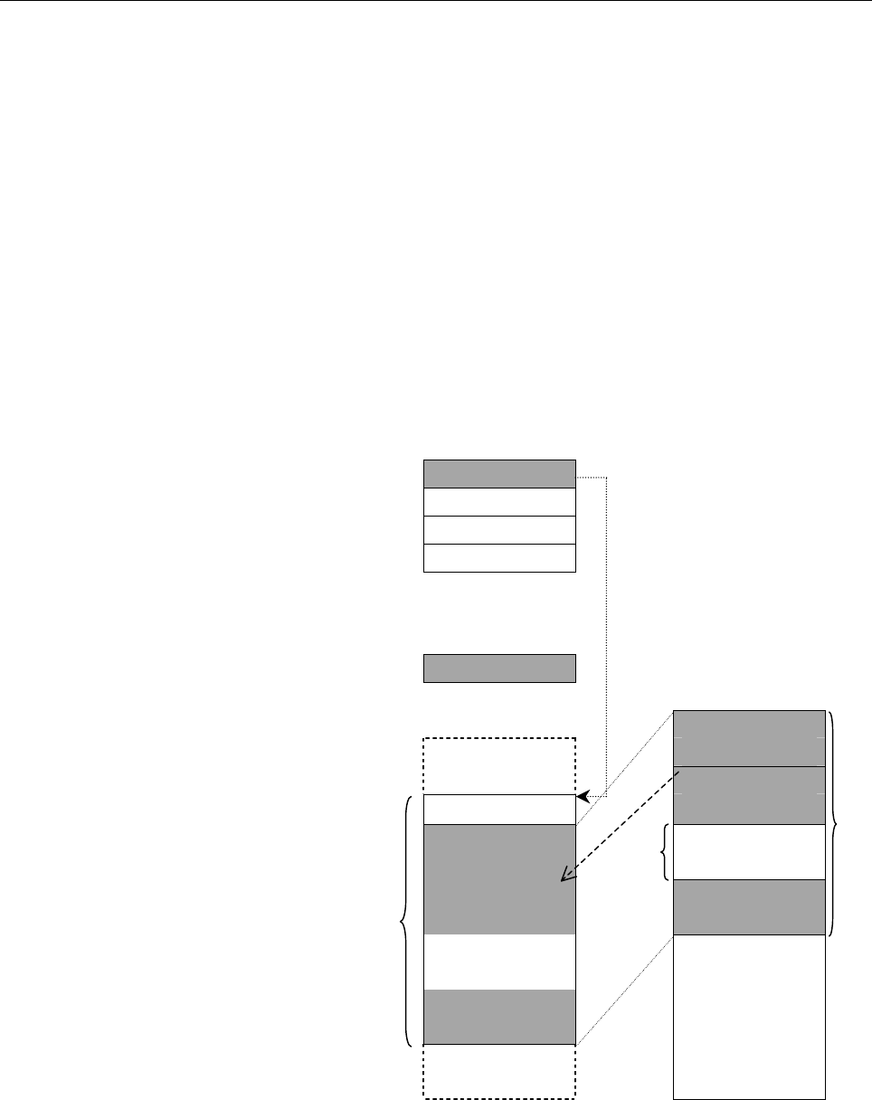
(3) The CNC monitors the switch flag at all times. When FFh is
written, the node number set in the PMC D area are taken in as
internal information, and the switch flag is set to 00h. At this
time, the CNC once updates the specified node status information
according to the new settings before the switch flag is set to 00h.
So, the user program can read the status information immediately
after checking that the switch flag is set to 00h.
(4) Until FFh is written to the switch flag, the user program can read
the node information of a specified node number from the PMC
area.
(5) Until FFh is written to the switch flag, the CNC writes the node
information of a specified node number to the specified area in
the PMC area. The DI data can be read regardless of whether
the switch flag is set to 00h.
PMC D area
7 0
Dxxxx+0 Node number
Dxxxx+2 DI offset
Dxxxx+4 Data size
Dxxxx+6 DO offset
PMC E/R area
Switch flag
Common memory
area 2
15 0
PMC area Transmit data
from other nodes
Transmit data
Information on other
nodes
from other nodes
DI data Transmit data of
the local node
Transmit data
from other nodes
Pa43→
Pa44→
Pa42→
(
Note 3
)
Pa45→
Pa46
Pa40→
Pa41
Contents Summary of F L-net Board for FANUC Series 30i/300i, 31i/310i, 32i/320i-MODEL A Operators manual
- Page 1FANUC F L-net Board For FANUC Series 30*/300*, 31*/310*, 32*/320*-MODEL A OPERATOR’S MANUAL B-64164EN/01
- Page 2• No part of this manual may be reproduced in any form. • All specifications and designs are subject to change without notice. The export of this product is subject to the authorization of the government of the country from where the product is exported. In this manual we have tried as much as possi
- Page 3B-64164EN/01 SAFETY PRECAUTIONS SAFETY PRECAUTIONS This section describes the safety precautions related to the use of CNC units, to ensure safe operation of machines fitted with FANUC CNC units. Read this section carefully before attempting to use any function described in this manual. Users should
- Page 4SAFETY PRECAUTIONS B-64164EN/01 1.1 DEFINITION OF WARNING, CAUTION, AND NOTE This manual includes safety precautions for protecting the user and preventing damage to the machine. Precautions are classified into Warnings and Cautions according to their bearing on safety. Also, supplementary informati
- Page 5B-64164EN/01 SAFETY PRECAUTIONS 1.2 GENERAL WARNINGS AND CAUTIONS WARNING 1 Before operating the machine, thoroughly check the entered data. Operating the machine with incorrectly specified data may result in the machine behaving unexpectedly, possibly causing damage to the workpiece and/or machine
- Page 6SAFETY PRECAUTIONS B-64164EN/01 CAUTION 1 Immediately after switching on the power, do not touch any of the keys on the MDI panel until the position display or alarm screen appears on the CNC unit. Some of the keys on the MDI panel are dedicated to maintenance or other special operations. Pressing a
- Page 7B-64164EN/01 TABLE OF CONTENTS TABLE OF CONTENTS SAFETY PRECAUTIONS............................................................................s-1 I. GENERAL 1 GENERAL ............................................................................................... 3 1.1 ORGANIZATION OF THIS MANUAL ..
- Page 8TABLE OF CONTENTS B-64164EN/01 3.4.1 Byte Block Read.....................................................................................................50 3.4.2 Byte Block Write....................................................................................................52 3.4.3 Word Block Re
- Page 9B-64164EN/01 TABLE OF CONTENTS 2 CABLE CONNECTION ....................................................................... 113 2.1 CONNECTING TO ETHERNET ................................................................ 114 2.2 LEADING OUT THE ETHERNET CABLE ...........................................
- Page 10
- Page 11I. GENERA
- Page 12
- Page 13B-64164EN/01 GENERAL 1.GENERAL 1 GENERAL This manual describes the FL-net functions of the FANUC Series 30i/300i, 31i/310i, 32i/320i -A. This chapter explains the organization of this manual and applied models. -3-
- Page 141.GENERAL GENERAL B-64164EN/01 1.1 ORGANIZATION OF THIS MANUAL This manual consists of the following parts: SAFETY PRECAUTIONS Describes the precautions which must be observed when any of the functions explained in this manual is used. I. GENERAL Explains the organization of this manual, lists appli
- Page 15B-64164EN/01 GENERAL 1.GENERAL 1.2 APPLICABLE MODELS The models covered in this manual are as follows. The abbreviations listed below may be used to refer to the corresponding models. Model name Abbreviation FANUC Series 30i-A Series 30i-A 30i-A 30i-A FANUC Series 300i-A Series 300i-A 300i-A FANUC S
- Page 162.OVERVIEW OF FL-net FUNCTIONS GENERAL B-64164EN/01 2 OVERVIEW OF FL-net FUNCTIONS This chapter describes the specifications of FL-net functions. -6-
- Page 17B-64164EN/01 GENERAL 2.OVERVIEW OF FL-net FUNCTIONS 2.1 WHAT IS THE FL-net The FL-net is a control-level, open FA network standardized by the FA Open Systems Promotion Forum (FAOP) in the Manufacturing Science and Technology Center, which is an outside organization of the Ministry of Economy, Trade
- Page 182.OVERVIEW OF FL-net FUNCTIONS GENERAL B-64164EN/01 Two communication functions available according to the application The FL-net supports both the common memory function and message communication function. The common memory function uses cyclic data transmission to allow the nodes to always share t
- Page 19B-64164EN/01 GENERAL 2.OVERVIEW OF FL-net FUNCTIONS High reliability Each node can participate in or be disconnected from the FL-net at any time. So, the power to each node can be turned on or off without restraint to provide high maintainability. The masterless token method allows communication to
- Page 202.OVERVIEW OF FL-net FUNCTIONS GENERAL B-64164EN/01 2.2 FANUC FL-net FUNCTIONS Cyclic data transmission With the FANUC FL-net, part of large-capacity common memory can be allocated in the PMC E area, R area, or D area to allow the user program to read and write data in the FL-net common memory. Cycl
- Page 21B-64164EN/01 GENERAL 2.OVERVIEW OF FL-net FUNCTIONS Cyclic data transmission FL-net PMC memory PMC memory User User program program FL-net board FL-net board For details of message data transmission, see Chapter 3, "Message Transmission," in "II. Specification." NOTE The FL-net communication standar
- Page 22
- Page 23II. SPECIFICATIO
- Page 24
- Page 25B-64164EN/01 SPECIFICATION 1.PARAMETERS FOR FL-net FUNCTION 1 PARAMETERS FOR FL-net FUNCTION The parameters for the FL-net function are divided into six major groups: (1) Basic parameters (2) State monitoring parameters (3) Area 1 allocation parameters (4) Area 2 allocation parameters (5) Message al
- Page 261.PARAMETERS FOR FL-net FUNCTION SPECIFICATION B-64164EN/01 (2) State monitoring parameters These parameters are used to assign local node status data and remote node status data to the PMC area so that the user program can monitor the statuses of the local node and remote nodes. Table 1-2 State Mon
- Page 27B-64164EN/01 SPECIFICATION 1.PARAMETERS FOR FL-net FUNCTION Table 1-5 Area 2 Allocation Parameters (Separate Allocation for Each of DI and DO) Parameter Parameter name Description number PMC start address Start address of a common Pa40 (for DO) memory area in the PMC E area, R area, or D area that s
- Page 281.PARAMETERS FOR FL-net FUNCTION SPECIFICATION B-64164EN/01 (6) Bit parameters Table 1-7 Bit parameters Parameter Parameter name Description number Parameter 1 Parameter for FL-net data Pa60 transfer Parameter 2 Parameter for FL-net operation Pa61 For each FL-net function used, the parameters below
- Page 29B-64164EN/01 SPECIFICATION 2.CYCLIC TRANSMISSION 2 CYCLIC TRANSMISSION This chapter details how to use the cyclic data transmission function of the FL-net function. - 19 -
- Page 302.CYCLIC TRANSMISSION SPECIFICATION B-64164EN/01 2.1 COMMON MEMORY AREA 1 CYCLIC TRANSMISSION Those areas of common memory area 1 that are to be used for data exchange can be allocated in the PMC E area or R are in direct image. Related parameters (1) Pa11: Area 1 address (2) Pa12: Area 1 size (in w
- Page 31B-64164EN/01 SPECIFICATION 2.CYCLIC TRANSMISSION 2.2 COMMON MEMORY AREA 2 CYCLIC TRANSMISSION Data exchange with common memory area 2 is performed using one of the following two methods: (1) Simultaneous allocation of DI and DO areas Like the method for data exchange with common memory area 1, commo
- Page 322.CYCLIC TRANSMISSION SPECIFICATION B-64164EN/01 2.2.1 Simultaneous DI and DO Area Allocation Areas of common memory area 2 that are to be used for data exchange can be allocated to the E, R, or D area of the PMC just as they are allocated in common memory. Related parameters (1) Pa13: Area 2 addres
- Page 33B-64164EN/01 SPECIFICATION 2.CYCLIC TRANSMISSION 2.2.2 Separate Allocation of DI and DO Areas For data exchange with common memory area 2, DI and DO areas can be set separately to allocate them to the E, R, or D area of the PMC. NOTE When a small amount of data in common memory area 2 is to be excha
- Page 342.CYCLIC TRANSMISSION SPECIFICATION B-64164EN/01 Allocation when common memory area 2 of the local node is too large When common memory area 2 of the local node is too large to prepare DO data of the local node in the PMC area at one time, an offset can be specified by a user program (such as a ladd
- Page 35B-64164EN/01 SPECIFICATION 2.CYCLIC TRANSMISSION PMC area and common memory area 2 PMC D area 7 0 Pa43→ Dxxxx+0 Node number Dxxxx+2 DI offset Dxxxx+4 Data size Dxxxx+6 O offset PMC E/R area Common memory Pa44→ Switch flag area 2 15 0 PMC area Transmit data from other nodes Pa13→ Transmit data of Pa4
- Page 362.CYCLIC TRANSMISSION SPECIFICATION B-64164EN/01 2.2.2.2 DI data allocation Whether to perform dynamic allocation or static allocation of DI data of common memory area 2 can be specified by the setting of Pa46 (allocation size (for DI)). Dynamic DI data allocation of common memory area 2 The user pr
- Page 37B-64164EN/01 SPECIFICATION 2.CYCLIC TRANSMISSION (3) The CNC monitors the switch flag at all times. When FFh is written, the node number, DI offset, and data size set in the PMC D area are taken in as internal information, and the switch flag is set to 00h. At this time, the CNC once reads DI data a
- Page 382.CYCLIC TRANSMISSION SPECIFICATION B-64164EN/01 NOTE 2 Information on other nodes is 4 bytes in size. So, for an area in the PMC area to be allocated for DI, allocate an area 4 bytes larger than the value set in Dxxxx+4 (data size (in words). When the user program handles DI data in area 2, the dat
- Page 39B-64164EN/01 SPECIFICATION 2.CYCLIC TRANSMISSION Static DI data allocation of common memory area 2 This allocation method fixes the DI data area. With this method, an area larger than that allocated with the dynamic allocation method can be allocated in the PMC area. Only node status information can
- Page 402.CYCLIC TRANSMISSION SPECIFICATION B-64164EN/01 (3) The CNC monitors the switch flag at all times. When FFh is written, the node number set in the PMC D area are taken in as internal information, and the switch flag is set to 00h. At this time, the CNC once updates the specified node status informa
- Page 41B-64164EN/01 SPECIFICATION 2.CYCLIC TRANSMISSION NOTE 1 As shown in the above example, the area specified by Pa46 (allocation size (for DI)) can contain the local node transmit data area. In this case, the corresponding PMC area can be specified for Pa40 (PMC start address (for DO)) to allocate no w
- Page 422.CYCLIC TRANSMISSION SPECIFICATION B-64164EN/01 2.2.2.3 Nodes information Information on other nodes and DI data are allocated in the PMC area as follows: 7 0 Pa42→ +0 (Reserved) +1 FA link layer state +2 Upper layer state +4 DI data FA link layer state: 1 byte 7 6 5 4 3 2 1 0 +1 <1> <2> <3> <4> (R
- Page 43B-64164EN/01 SPECIFICATION 2.CYCLIC TRANSMISSION 2.2.2.4 Timing of switching between conditions on data exchange with common memory area 2 In data exchange between common memory area 2 and the PMC area, the user can switch between data (nodes information) exchange conditions. The timing of data swit
- Page 442.CYCLIC TRANSMISSION SPECIFICATION B-64164EN/01 2.3 NODE STATE MONITORING 2.3.1 Allocation of Local Node State The state of the local node can be monitored by allocating the 8-byte state code of the local node in the PMC E area or the PMC R area. Related parameters <1> Pa20: Local node status Data
- Page 45B-64164EN/01 SPECIFICATION 2.CYCLIC TRANSMISSION Table 2-1 Local Node State Item Description Token monitoring time Set when transmission does not terminate error flag within the token monitoring time (Pa15) set for the local node. Initialization error flag Set when an initialization parameter or a p
- Page 462.CYCLIC TRANSMISSION SPECIFICATION B-64164EN/01 Upper layer state: 2 bytes 7 6 5 4 3 2 1 0 +2 <8> <9> <10> <11> <12> <13> <14> <15> +3 <1> <2> <3> (Reserved) <4> <5> <6> <7> U_ERR_CODE <4> (Highest bit) to <15> (Lowest bit) (This code is not used with this device.) <2>, <3> U_ERR 00: NORMAL 01: WAR
- Page 47B-64164EN/01 SPECIFICATION 2.CYCLIC TRANSMISSION Current RCT value: 2 bytes 7 6 5 4 3 2 1 0 +4 <9> <10> <11> <12> <13> <14> <15> <16> +5 <1> <2> <3> <4> <5> <6> <7> <8> Current RCT value: <1> (Highest bit) to <16> (Lowest bit) Table 2-4 Current RCT value Item Description Current RCT value Refresh Cy
- Page 482.CYCLIC TRANSMISSION SPECIFICATION B-64164EN/01 2.3.2 Allocation of a List of Participating Nodes A list of the numbers of the nodes participating in the network can be allocated in the PMC E area or the PMC R area to monitor the participation state. Related parameters (1) Pa20: A list of participa
- Page 49B-64164EN/01 SPECIFICATION 2.CYCLIC TRANSMISSION 2.4 BYTE LIST OF CYCLIC DATA A byte list in a common memory area is related with a byte list in the PMC area as described below. Common memory area and the PMC area On FL-net Common PMC area line memory area 7 0 15 0 7 0 +00 12H +00 3412H +00 34H +01
- Page 503.MESSAGE TRANSMISSION SPECIFICATION B-64164EN/01 3 MESSAGE TRANSMISSION This chapter details how to use the message transmission function of the FL-net function. - 40 -
- Page 51B-64164EN/01 SPECIFICATION 3.MESSAGE TRANSMISSION 3.1 LIST OF MESSAGE TRANSMISSION SERVICES The message transmission function of the FANUC FL-net function supports the services listed in Table 3-1. Table 3-1 List of Services Supported Message service item Client Server function function Byte block r
- Page 523.MESSAGE TRANSMISSION SPECIFICATION B-64164EN/01 3.2 OVERVIEW OF THE MESSAGE TRANSMISSION FUNCTION The function for transmitting messages other than transparent messages involves a client function and server function. For a message transmitted from the client, the server returns a response message.
- Page 53B-64164EN/01 SPECIFICATION 3.MESSAGE TRANSMISSION The format of each interface area is described below. Transmit interface for the client and transparent messages The interface area specified by Pa50 (client function interface) has the format shown below. 7 0 Pa50→ +0 Transmission request/response f
- Page 543.MESSAGE TRANSMISSION SPECIFICATION B-64164EN/01 Table 3-2 Transmit Interface Items Interface item Description Direction Transmission Flag set by the user program to request message U→S request/respons transmission, and set by the CNC to post the S→U e flag (Note 1, 2) reception of a response messa
- Page 55B-64164EN/01 SPECIFICATION 3.MESSAGE TRANSMISSION NOTE 1 Transmission starts when the user program writes 0001h into the transmission request/response flag. Therefore, set 0001h after setting data in all other interface areas. While the transmission request/response flag is 0001h, the user program m
- Page 563.MESSAGE TRANSMISSION SPECIFICATION B-64164EN/01 Table 3-3 Error Codes of the Transmit Interface Error code Description 1st byte 2nd byte 81h 01h A specified node number is incorrect. 02h A specified transaction code is incorrect. 03h An area specified as a transmit/receive buffer in the PMC R area
- Page 57B-64164EN/01 SPECIFICATION 3.MESSAGE TRANSMISSION Receive interface for server function and transparent messages The interface area specified by Pa52 (server function interface) has the format shown below. 7 0 Pa52→ +0 Receive flag +2 Transmission source node number +3 (Reserved) +4 Transaction code
- Page 583.MESSAGE TRANSMISSION SPECIFICATION B-64164EN/01 3.3 PROCEDURE FOR MESSAGE TRANSMISSION OPERATION This section explains how the user program exchanges data with the system when messages are transmitted or received through message transmission. 3.3.1 Procedure for Message Transmission Operation Mess
- Page 59B-64164EN/01 SPECIFICATION 3.MESSAGE TRANSMISSION 3.3.2 Procedure for operating the transparent message transmission Because no response message is used for transparent messages, there is no need to wait for a response message. Transparent message transmission side User program System 1) Transparent
- Page 603.MESSAGE TRANSMISSION SPECIFICATION B-64164EN/01 3.4 MESSAGE TRANSMISSION CLIENT FUNCTION This section explains in detail the interfaces in the message section of each service of the message transmission client function. 3.4.1 Byte Block Read Request message Response message 7 0 7 0 Pa50→ +0 Transm
- Page 61B-64164EN/01 SPECIFICATION 3.MESSAGE TRANSMISSION Table 3-5 Byte Block Read Interface Items Interface item Description Direction Transaction Request message: 65003 U→S code Response message: 65203 S→U Offset address Request message: Offset address on virtual U→S on virtual address space of byte bloc
- Page 623.MESSAGE TRANSMISSION SPECIFICATION B-64164EN/01 3.4.2 Byte Block Write Request message Response message 7 0 7 0 Pa50→ +0 Transmission request +0 Response flag flag 0001h +2 +2 Request status +3 +3 Response status +4 Cancel flag +4 +5 Destination node +5 number +6 (Reserved) +6 (Reserved) +8 Transa
- Page 63B-64164EN/01 SPECIFICATION 3.MESSAGE TRANSMISSION Table 3-6 Byte Block Write Interface Items Interface item Description Direction Transaction Request message: 65004 U→S code Response message: 65204 S→U Offset address Request message: Offset address on virtual U→S on virtual address space of byte add
- Page 643.MESSAGE TRANSMISSION SPECIFICATION B-64164EN/01 3.4.3 Word Block Read Request message Response message 7 0 7 0 Pa50→ +0 Transmission request +0 Response flag flag 0001h +2 +2 Request status +3 +3 Response status +4 Cancel flag +4 +5 Destination node +5 number +6 (Reserved) +6 (Reserved) Pa51 +8 Tr
- Page 65B-64164EN/01 SPECIFICATION 3.MESSAGE TRANSMISSION Table 3-7 Word Block Read Interface Items Interface item Description Direction Transaction Request message: 65005 U→S code Response message: 65205 S→U Offset address Request message: Offset address on virtual U→S on virtual address space of word addr
- Page 663.MESSAGE TRANSMISSION SPECIFICATION B-64164EN/01 3.4.4 Word Block Write Request message Response message 7 0 7 0 Pa50→ +0 Transmission request +0 Response flag flag 0001h +2 +2 Request status +3 +3 Response status +4 Cancel flag +4 +5 Destination node +5 number +6 (Reserved) +6 (Reserved) +8 Transa
- Page 67B-64164EN/01 SPECIFICATION 3.MESSAGE TRANSMISSION Table 3-8 Word Block Write Interface Items Interface item Description Direction Transaction code Request message: 65006 U→S Response message: 65206 S→U Offset address on Request message: Offset address on virtual U→S virtual address address space of
- Page 683.MESSAGE TRANSMISSION SPECIFICATION B-64164EN/01 3.5 MESSAGE TRANSMISSION SERVER FUNCTION 3.5.1 Error Code List In response to a request from a client, the message data transmission server function automatically returns a response message without involving the user program. When the message transmi
- Page 69B-64164EN/01 SPECIFICATION 3.MESSAGE TRANSMISSION 3.5.2 Virtual Address Space Allocation Virtual address space used to read/write byte block and read/write word block is allocated in the PMC area as described below. Virtual address space for byte block data Table 3-10 Virtual Address Space for Byte
- Page 703.MESSAGE TRANSMISSION SPECIFICATION B-64164EN/01 Virtual address space for word block data Table 3-11 Virtual Address Space for Word Block Data Allocation in PMC Virtual address Remarks Symbol Type of signal Address space (decimal) (hexadecimal) X Signal from machine to PMC X0000 or higher 00000000
- Page 71B-64164EN/01 SPECIFICATION 3.MESSAGE TRANSMISSION 3.6 TRANSPARENT MESSAGE TRANSMISSION FUNCTION With the FANUC FL-net function, a transparent message of a transaction code (50000 to 59999) can be used as a transparent message for data transmission/reception by the user program. This section explains
- Page 723.MESSAGE TRANSMISSION SPECIFICATION B-64164EN/01 Table 3-12 Transparent Transmit Message Interface Items Interface item Description Direction Transaction code 50000 to 59999 U→S Data size Size of transparent data to be U→S transmitted (in words) Transmit data buffer Start address of an area in the
- Page 73B-64164EN/01 SPECIFICATION 3.MESSAGE TRANSMISSION 3.6.2 Transparent Message Reception Reception posted Reception confirmed 7 0 7 0 Pa52→+0 Receive flag +0 Completion flag 0001h 0000h +2 Transmission source +2 node number +3 (Reserved) +3 +4 Transaction code +4 Transaction code 50000 to 59999 50000 t
- Page 743.MESSAGE TRANSMISSION SPECIFICATION B-64164EN/01 3.7 SERVER FUNCTION OF TRANSMITTING A MESSAGE WITH CONFIRMATION When an ordinary byte block read/write or word block read/write service of the message transmission server function is executed, data is exchanged with the client without user-program in
- Page 75B-64164EN/01 SPECIFICATION 3.MESSAGE TRANSMISSION 3.7.1 Reception of a Message with Confirmation Reception posted Reception confirmed 7 0 7 0 Pa52→ +0 +0 Receive flag Completion flag 0001h 0000h +2 +2 Transmission source node number +3 +3 (Reserved) +4 +4 Pa53 Transaction code Transaction code 65003
- Page 763.MESSAGE TRANSMISSION SPECIFICATION B-64164EN/01 3.7.2 Response Message Transmission Transmission Transmission requested completed 7 0 7 0 Pa50→ +0 +0 Transmission request flag Completion flag 0001h +2 +2 Request status +3 +3 +4 +4 Cancel flag +5 +5 Destination node number +6 +6 (Reserved) (Reserve
- Page 77B-64164EN/01 SPECIFICATION 3.MESSAGE TRANSMISSION 3.7.3 Virtual Address Space Allocation Virtual address space used for byte block read/write and word block read/write with confirmation is allocated in the PMC area as described below. Virtual address space for byte block data with confirmation Table
- Page 783.MESSAGE TRANSMISSION SPECIFICATION B-64164EN/01 Virtual address space for word block data with confirmation Table 3-1 Virtual Address Space for Word Block Data with Confirmation Allocation in PMC Virtual address Remarks Address space (hexadecimal) Type of Symbol Type of signal (decimal) Symbol sig
- Page 79B-64164EN/01 SPECIFICATION 3.MESSAGE TRANSMISSION 3.8 BYTE LIST OF MESSAGE DATA In message transmission, the relationships between the sequence of data transmission over the network and the byte list in the virtual address space and PMC area are shown below. Byte block data and the PMC area On FL-ne
- Page 803.MESSAGE TRANSMISSION SPECIFICATION B-64164EN/01 Word block data and the PMC area Transparent data and the PMC area On FL-net Virtual address PMC area line space 7 0 15 0 7 0 +00 12H +00 3412H +00 34H +01 34H +01 7856H +01 12H +02 56H +02 78H +03 78H +03 56H The data list in the PMC area can be cha
- Page 81III. SETTIN
- Page 82
- Page 83B-64164EN/01 SETTING 1.SETTING OF FL-net FUNCTION 1 SETTING OF FL-net FUNCTION This part describes how to set the FL-net function CAUTION After setting DI/DO data, make sure communication is performed correctly in a state in which security is retained. Operating the system without confirmation may c
- Page 841.SETTING OF FL-net FUNCTION SETTING B-64164EN/01 1.1 PARAMETERS FOR FL-net FUNCTION The parameters for the FL-net function are divided into six major groups: (1) Basic parameters (2) State monitoring parameters (3) Area 1 allocation parameters (4) Area 2 allocation parameters (5) Message allocation
- Page 85B-64164EN/01 SETTING 1.SETTING OF FL-net FUNCTION (2) State monitoring parameters These parameters are used to assign local node status data and remote node status data to the PMC area so that the user program can monitor the statuses of the local node and remote nodes. Table 1-2 State Monitoring Pa
- Page 861.SETTING OF FL-net FUNCTION SETTING B-64164EN/01 Table 1-5 Area 2 Allocation Parameters (Separate Allocation for Each of DI and DO) Parameter Parameter name Description number PMC start address Start address of a common Pa40 (for DO) memory area in the PMC E area, R area, or D area that serves as t
- Page 87B-64164EN/01 SETTING 1.SETTING OF FL-net FUNCTION (6) Bit parameters Table 1-7 Bit parameters Parameter Parameter name Description number Parameter 1 Parameter for FL-net data Pa60 transfer Parameter 2 Parameter for FL-net operation Pa61 - 77 -
- Page 881.SETTING OF FL-net FUNCTION SETTING B-64164EN/01 Displaying the parameter screen Procedure 1 Press function key SYSTEM . 2 The [FL-net] soft key appears. (If the [FL-net] soft key is not displayed, press the next-menu key several times, which is located at the right end of soft keys.) 3 Pressing th
- Page 89B-64164EN/01 SETTING 1.SETTING OF FL-net FUNCTION Screen 1-1 FL-net PARAMETER Screen 7 As necessary, press the [(OPRT)] soft key, then use the following soft key: 8 If you set bit 2 (DTL) of Pa61 (parameter 2) to 1, the screen for DI/DO allocation of common memory area 2 on the fourth page is displa
- Page 901.SETTING OF FL-net FUNCTION SETTING B-64164EN/01 Setting item Each setting item is described below. Basic parameters Parameters for the FL-net function are set. Table 1-9 Basic Parameters Item Description IP ADDRESS IP address of the local node. Pa10 The host address section (last numeric value) of
- Page 91B-64164EN/01 SETTING 1.SETTING OF FL-net FUNCTION State monitoring parameters The state monitoring parameters are used to allocate areas in the PMC area to which the states of the local node and other nodes are posted. Table 1-10 Area 1 Allocation Parameters Item Description OWN STATUS Specify the s
- Page 921.SETTING OF FL-net FUNCTION SETTING B-64164EN/01 Bit parameters The bit parameters are used to specify data conversion at the time of FL-net data transfer and to make other settings. Table 1-11 Bit Parameters Item Description Parameter 1 Bit parameters for FL-net data transfer. Pa60 Bit 0: CYC Byte
- Page 93B-64164EN/01 SETTING 1.SETTING OF FL-net FUNCTION CAUTION 1 The E area in the PMC area is normally allocated to volatile memory. It, however, can also be used optionally as nonvolatile memory. When the area is set as nonvolatile memory, the contents of the area are retained even after the power is t
- Page 941.SETTING OF FL-net FUNCTION SETTING B-64164EN/01 Area 2 allocation parameters The area 2 allocation parameters are used for allocation-related settings to enable data exchange between common memory area 2 and the PMC E area, the PMC R area, or the PMC D area. Table 1-13 Area 2 Allocation Parameters
- Page 95B-64164EN/01 SETTING 1.SETTING OF FL-net FUNCTION NOTE 1 Only a PMC area at an even-numbered address can be set for the above area. 2 The unit of size set in this parameter is words. This means that for an area used in the PMC E area, the PMC R area or the PMC D area, the number of bytes as many as
- Page 961.SETTING OF FL-net FUNCTION SETTING B-64164EN/01 CAUTION 1 When nonvolatile memory in the PMC area is used, the memory contents are retained even after the power is turned off. So, special attention should be paid not to cause an unpredictable operation when the power is turned on next time. 2 When
- Page 97B-64164EN/01 SETTING 1.SETTING OF FL-net FUNCTION Message allocation parameters The message allocation parameters are used to allocate a message transmit interface area in the PMC E area, the PMC R area, or the PMC D area. Table 1-15 Message Allocation Parameters Item Description CLIENT I/F Specify
- Page 981.SETTING OF FL-net FUNCTION SETTING B-64164EN/01 1.2 MAINTENANCE SCREENS OF FL-net FUNCTION The FL-net maintenance screens include the FL-net NODE MONITOR screen, the FL-net NETWORK screen, and the FL-net LOG screen. The FL-net NODE MONITOR screen provides information such as nodes participating in
- Page 99B-64164EN/01 SETTING 1.SETTING OF FL-net FUNCTION 1.2.1 Participating-Node Management Table Nodes participating in the FL-net network, parameters of each node, and other information are displayed on this screen. Procedure 1 Press the [NODE] soft key. The NODE MONITOR screen (Screen 1-3 FL-net Node M
- Page 1001.SETTING OF FL-net FUNCTION SETTING B-64164EN/01 4 As necessary, press the [(OPRT)] soft key, then use the following soft keys: SELECT NODE When you enter a node number by using the MDI keys then press the [SELECT NODE] soft key, information about the entered node number is displayed. PREV NODE NEX
- Page 101B-64164EN/01 SETTING 1.SETTING OF FL-net FUNCTION Display item Item Description Node status list A list of the statuses of nodes is displayed. *: Local node O: Node participating in the network -: Node not participating in the network NODE NUMBER Indicates a node number. A number from 1 to 254 is di
- Page 1021.SETTING OF FL-net FUNCTION SETTING B-64164EN/01 Item Description LKS The FA link layer status of a node on which the cursor is positioned is indicated in hexadecimal notation. Bit 7: Duplicate address detection flag This bit is set to 1 when a setting for common memory area 1 or 2 is the same as a
- Page 103B-64164EN/01 SETTING 1.SETTING OF FL-net FUNCTION NOTE 1 The token mode varies depending on whether the version of the FL-net communication standards is version 1.00 or version 2.00. If the communication disable detection flag is set, ensure that all nodes comply with FL-net communication standards
- Page 1041.SETTING OF FL-net FUNCTION SETTING B-64164EN/01 1.2.2 Network Management Table The FL-net network management table screen allows the user to reference the parameters of each node in the FL-net network management table. Procedure 1 Press the [NETWORK] soft key. The NETWORK screen (Screen 1-5) then
- Page 105B-64164EN/01 SETTING 1.SETTING OF FL-net FUNCTION 1.2.3 Log Information Management Table This screen provides network log information of the local node. Procedure 1 Press the [LOG] soft key. The LOG screen (Screen 1-6 FL-net Log Screen) then appears. Screen 1-6 FL-net Log Screen 2 As necessary, pres
- Page 1061.SETTING OF FL-net FUNCTION SETTING B-64164EN/01 Item Description DUPLICATED Indicates the number of times a duplicate token was TOKEN detected. DESTROYED Indicates the number of times a token was discarded when its TOKEN duplication was detected, REISSUE TOKEN Indicates the number of times a token
- Page 107B-64164EN/01 SETTING 1.SETTING OF FL-net FUNCTION 1.3 NOTES ON LADDER PROGRAM CREATION This section provides necessary notes on ladder program creation to build a safety system that uses the FL-net. Input and output signals An output signal from the CNC is processed by a ladder program, and written
- Page 1081.SETTING OF FL-net FUNCTION SETTING B-64164EN/01 Ladder program processing and refresh processing of FL-net function Ladder program processing and refresh processing of the FL-net function operate asynchronously. Because ladder program processing can be performed independently of refresh processing
- Page 109B-64164EN/01 SETTING 1.SETTING OF FL-net FUNCTION CAUTION Refresh processing of the FL-net function is performed not in synchronization with the execution of the ladder program. Therefore, when creating a ladder program, note the following: 1 When an FL-net input signal set at a specified PMC addres
- Page 1101.SETTING OF FL-net FUNCTION SETTING B-64164EN/01 Data concurrency When a ladder program uses DI data or DO data in long data (4-byte data) units and in word data (2-byte data) units, concurrency of multiple bytes of data (with no data split) is guaranteed under the restrictions explained below. CAU
- Page 111B-64164EN/01 SETTING 2.EXAMPLE OF CONNECTION 2 EXAMPLE OF CONNECTION This chapter describes an example of connection using the FL-net function with the Series 30i/31i/32i-A. - 101 -
- Page 1122.EXAMPLE OF CONNECTION SETTING B-64164EN/01 2.1 EXAMPLE OF CONFIGURATION Using the example of configuration shown below, this section describes the setting of each parameter. FL-net Series 30i-A Series 31i-A Series 32i-A Node No. #1 Node No. #2 Node No. #3 Fig. 2-1 Example of FL-net Configuration T
- Page 113B-64164EN/01 SETTING 2.EXAMPLE OF CONNECTION 2.2 EXAMPLE OF PARAMETER SETTINGS Assume that the address map of the PMC R area of each node is as shown below. Then, the parameters of each node are set as indicated in Table 2-1 through Table 2-3. PMC R area 1:R0000 Local node information 1:R0008 Partic
- Page 1142.EXAMPLE OF CONNECTION SETTING B-64164EN/01 Table 2-1 Parameters of Node No. #1 Item Setting Item Setting Pa10 IP ADDRESS 192.168.250.1 Area 1 DI/DO allocation - Pa17 NODE NAME FS30i-A Pa30 PMC ADDRESS 1:R0100 Pa11 AREA 1 ADDRESS 0 Pa31 AREA 1 ADDRESS 0 Pa12 AREA 1 SIZE 4 Pa32 ALLOCATED SIZE 12 Pa1
- Page 115B-64164EN/01 SETTING 2.EXAMPLE OF CONNECTION 2.3 IMAGE OF DATA EXCHANGE When data exchange is performed with the examples of configuration and parameter settings described earlier, the illustration below shows how the data of each node is viewed in the PMC R area of each node. Node No. Node No. Node
- Page 116
- Page 117IV. CONNECTIO
- Page 118
- Page 119B-64164EN/01 CONNECTION 1.INSTALLATION 1 INSTALLATION This chapter provides information required for installation of the FL-net board. - 109 -
- Page 1201.INSTALLATION CONNECTION B-64164EN/01 1.1 SPECIFICATIONS This section describes hardware specifications of the FL-net board. Name Ordering code A02B-0303-J272 Board drawing A20B-8101-0031 number FANUC Series 30i/300i/300is-MODEL A FANUC Series 31i/310i/310is-MODEL A5 Applicable model FANUC Series 3
- Page 121B-64164EN/01 CONNECTION 1.INSTALLATION 1.2 INSTALLATION This section describes information about the installation of the FL-net board. 1.2.1 Mounting into the LCD-mounted Type Unit The board is mounted into an option slot of the control unit. It occupies one slot. The option slot does not have mount
- Page 1221.INSTALLATION CONNECTION B-64164EN/01 1.2.3 Total Connection Diagram FL-net board CD38N 1 TX+ 2 TX- 3 RX+ HUB 4 5 6 RX- 7 8 - 112 -
- Page 123B-64164EN/01 CONNECTION 2.CABLE CONNECTION 2 CABLE CONNECTION This chapter describes information relating to the Ethernet connection. CAUTION 1 Devices that transmit communication data of an Ethernet other than the FL-net must not be connected to the FL-net network. If such a device is connected, FL
- Page 1242.CABLE CONNECTION CONNECTION B-64164EN/01 2.1 CONNECTING TO ETHERNET The FL-net board is provided with a 10BASE-T interface. Prepare a hub for connecting the FL-net board to the Ethernet trunk. The following shows an example of a general connection. Some devices (hub, transceiver, etc.) that are ne
- Page 125B-64164EN/01 CONNECTION 2.CABLE CONNECTION 2.2 LEADING OUT THE ETHERNET CABLE 1) LCD-mounted type For this type of control unit, the cable is led out from the bottom of the control unit. See the outline drawing of the board for the location of the connector. Control unit Twisted-pair cable The radiu
- Page 1262.CABLE CONNECTION CONNECTION B-64164EN/01 2.3 10BASE-T CONNECTOR (CD38N) PIN ASSIGNMENTS CD38N Pin No. Signal name Description 1 TX+ Send + 2 TX- Send - 3 RX+ Receive + 4 Not used 5 Not used 6 RX- Receive - 7 Not used 8 Not used - 116 -
- Page 127B-64164EN/01 CONNECTION 2.CABLE CONNECTION 2.4 TWISTED-PAIR CABLE SPECIFICATION 2.4.1 Cable Connection The cable used for connection between the 10BASE-T interface, CD38N, of the FL-net board and the hub is connected as follows: FL-net board HUB CD38N 1 TX+ RJ-45 1 TX+ 2 TX- modular connector 2 TX-
- Page 1282.CABLE CONNECTION CONNECTION B-64164EN/01 2.4.2 Cable Materials CAUTION Unshielded cable (UTP cable) is commercially available as 10BASE-T twisted-pair cable: You should, however, use shielded Category 5 twisted-pair cable (STP cable) to improve the resistance to electrical noise in an FA environme
- Page 129B-64164EN/01 CONNECTION 2.CABLE CONNECTION Recommended cable (for movable parts) Manufacturer Specification Remarks Oki Electric Cable Co., AWG26 4P TPMC-C5-F(SB) Ltd. Dedicated to Shinko Electric Industrial FANUC FNC-118 Co., Ltd. Specification • Electric characteristics: Conforms to EIA/TIA 568A C
- Page 1302.CABLE CONNECTION CONNECTION B-64164EN/01 2.4.3 Connector Specification Use an 8-pin modular connector (RJ-45) with the twisted-pair cable for the Ethernet connection. The following connectors or equivalents must be used. For general use Specification Manufacturer Remarks Solid wire 5-569530-3 AMP
- Page 131B-64164EN/01 CONNECTION 2.CABLE CONNECTION 2.4.4 HUB Recommended hub Manufacturer Specification Remarks Contec Co., Ltd. RT-1008H 10BASE-T Eight ports Phoenix Contact FL HUB 10BASE-T 10BASE-T Four ports NOTE Before using the hub, refer to the operation manual supplied by the manufacturer. Contact po
- Page 1322.CABLE CONNECTION CONNECTION B-64164EN/01 2.5 ELECTRICAL NOISE COUNTERMEASURES 2.5.1 Separating Signal Lines For signal line separation, refer to the description of noise protection in the Connection Manual (Hardware) of CNC. The wiring for the Ethernet cable is of group C. 2.5.2 Clamping and Shiel
- Page 133B-64164EN/01 CONNECTION 2.CABLE CONNECTION The FL–net boards in an optional slots of CNC machines are connected to the hub through twisted pair cables. The cables are shielded with clamping hardware. Be sure to perform shielding since it is very important for stabilization of the system operation. S
- Page 1342.CABLE CONNECTION CONNECTION B-64164EN/01 8mm Ground plate 12mm 20mm Details of clamp fixture mounting holes 55mm max. 28mm 6mm 17mm External dimensions of clamp fixture NOTE 1 Unlike ordinary Ethernet communication, FL-net communication does not perform retransmission processing that is performed
- Page 135B-64164EN/01 CONNECTION 2.CABLE CONNECTION 2.5.3 Grounding the Network Even if the grounding condition on the machine side is satisfied, the communication line can pick up noise from the machine, depending on the machine installation condition and environment, thus resulting in a communication error
- Page 1362.CABLE CONNECTION CONNECTION B-64164EN/01 NOTE 1 The ground between PC/HUB side and machine system side must be separated. If it is impossible to separate the ground because there is only one grounding point, connect the ground cable for each system to the grounding point independently. (See figure
- Page 137V. MAINTENANC
- Page 138
- Page 139B-64164EN/01 MAINTENANCE 1.HARDWARE MAINTENANCE INFORMATION 1 HARDWARE MAINTENANCE INFORMATION This chapter provides hardware maintenance information related to the FL-net functions. - 129 -
- Page 1401.HARDWARE MAINTENANCE INFORMATION MAINTENANCE B-64164EN/01 1.1 BOARD This section describes the maintenance information for the FL-net board. 1.1.1 Component Layout LSI MPU CD38N Name PCB drawing No. Remarks FL-net board A20B-8101-0031 - 130 -
- Page 141B-64164EN/01 MAINTENANCE 1.HARDWARE MAINTENANCE INFORMATION 1.1.2 LED Indications and Meanings The FL-net board has four green LEDs (1 to 4) and one red LED (ALM) for state indication, and two green LEDs (BTX and LIL), one red LED (COL), and one yellow LED (COM) for communication status indication.
- Page 1421.HARDWARE MAINTENANCE INFORMATION MAINTENANCE B-64164EN/01 LED display transition for LED1, LED2, LED3, and LED4 (during power-on) LED indication Status Meaning 4321 Power-off Immediately after Initial state entered immediately after power-on. power-on If the board is stopped in this cond
- Page 143B-64164EN/01 MAINTENANCE 1.HARDWARE MAINTENANCE INFORMATION LED1, LED2, LED3, and LED4 indications (when abnormality occurs) The STATUS LEDs are turned on and off repeatedly with long on-time and short on-time. LED LED Status Description indication indication [Long on-time] [Short on-time] 4321 4321
- Page 1442.SOFTWARE MAINTENANCE INFORMATION MAINTENANCE B-64164EN/01 2 SOFTWARE MAINTENANCE INFORMATION This chapter provides software maintenance information related to the FL-net functions. - 134 -
- Page 145B-64164EN/01 MAINTENANCE 2.SOFTWARE MAINTENANCE INFORMATION 2.1 FL-net COMMUNICATION HISTORY Communication history of the FL-net function is displayed. FL-net COMMUNICATION HISTORY screen Procedure 1 Press function key MESSAGE . 2 Press the [FL-net MSG] soft key. The FL-net COMMUNICATION HISTORY scr
- Page 1462.SOFTWARE MAINTENANCE INFORMATION MAINTENANCE B-64164EN/01 The displayed contents can be changed by using soft keys on the FL-net COMMUNICATION HISTORY screen. (1) [ALL] soft key Displays all communication history information related to FL-net communication. (2) [ERROR] soft key Displays only error
- Page 147B-64164EN/01 MAINTENANCE 2.SOFTWARE MAINTENANCE INFORMATION Error message Meaning and action to be taken The protocol version of the local node is different from the protocol version of the already existing E-0203 My protocol version is different [999] network. The FANUC FL-net employs FL-net commun
- Page 148
- Page 149B-64164EN/01 INDEX INDEX
10BASE-T CONNECTOR (CD38N) PIN Grounding the Network.................................................125 ASSIGNMENTS........................................................... 116 HARDWARE MAINTENANCE INFORMATION .....129 Allocation of a List of Particip - Page 150INDEX B-64164EN/01
Reception of a Message with Confirmation .................... 65 RELATED MANUALS ....................................................5 Response Message Transmission .................................... 66 Separate Allocation of DI and DO Areas ........................ 23 S - Page 151Revision Record FANUC FL-net Board For FANUC Series 30i/300i, 31i/310i, 32i/320i-MODEL A OPERATOR’S MANUAL (B-64164EN) 01 Aug., 2004 Edition Date Contents Edition Date Contents
- Page 152