Specifications of Servo-Spindle synchronous control function Supplement to Manual Page 5
Supplement to Manual
A-78808E
Sheet
Title
Draw
No.
Ed.
Ed.Ed.
Ed. Date
DateDate
Date Design
DesignDesign
Design Description
DescriptionDescription
Description
Date
DateDate
Date May.29.’02 Desig.
Desig.Desig.
Desig. A.Fukumoto Apprv
ApprvApprv
Apprv.
..
. T.Endo
FANUC Series 16i /18i -TB
Specifications of Servo-Spindle synchronous control
function
5/
17
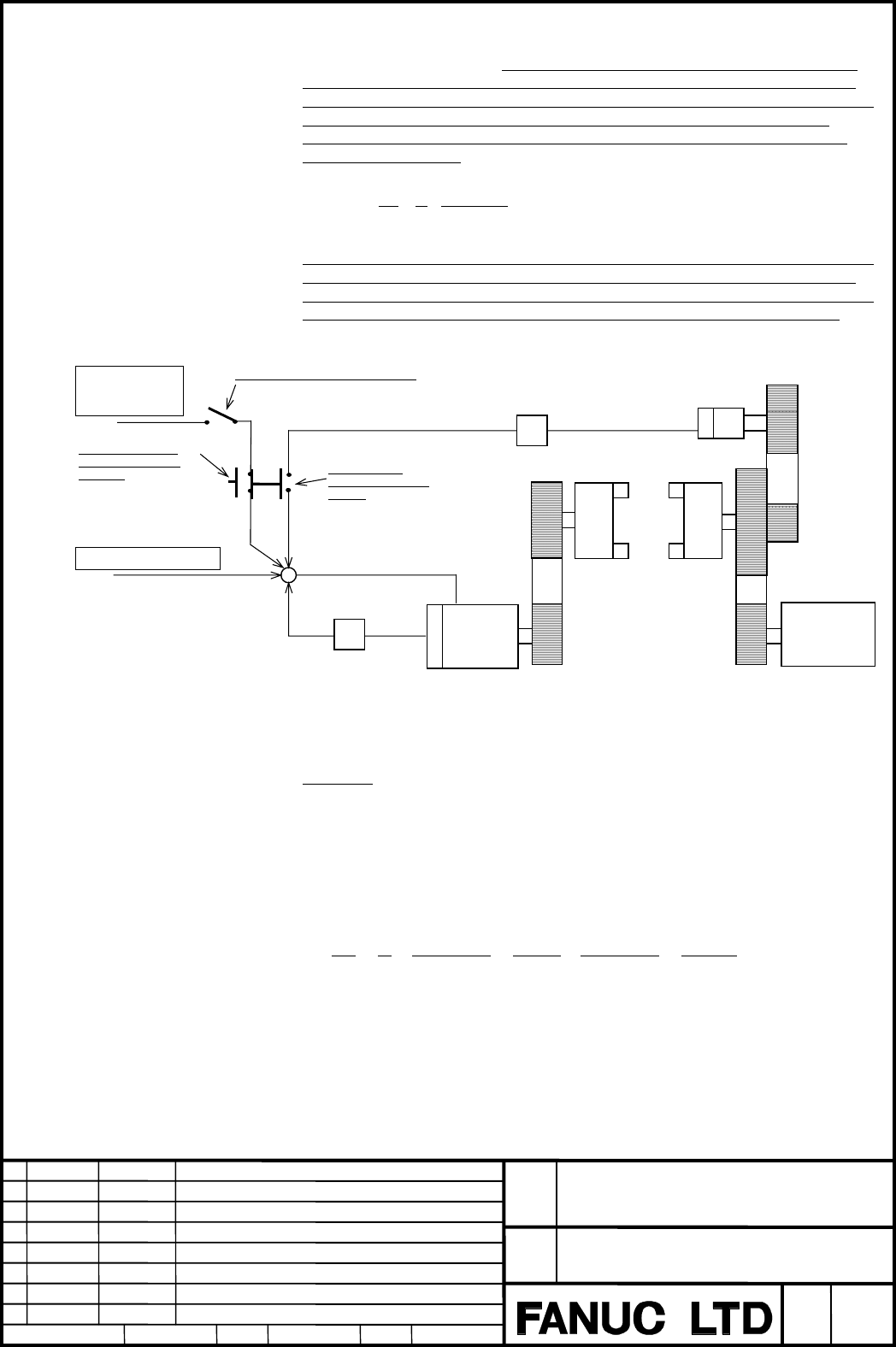
2.2 Configuration
When this function is used, it is necessary to adjust the detection
it is necessary to adjust the detection it is necessary to adjust the detection
it is necessary to adjust the detection unit
unit unit
unit to the
to theto the
to the
value that the number of pulses for spindle one revolution becomes 4096 by
value that the number of pulses for spindle one revolution becomes 4096 byvalue that the number of pulses for spindle one revolution becomes 4096 by
value that the number of pulses for spindle one revolution becomes 4096 by
setting flexible feed gear (M/N). Therefore, it is necessary to select ratio
setting flexible feed gear (M/N). Therefore, it is necessary to select ratio setting flexible feed gear (M/N). Therefore, it is necessary to select ratio
setting flexible feed gear (M/N). Therefore, it is necessary to select ratio a
aa
a:b of
:b of:b of
:b of
the gear of the servo motor and the spindle so that the value of M of the
the gear of the servo motor and the spindle so that the value of M of thethe gear of the servo motor and the spindle so that the value of M of the
the gear of the servo motor and the spindle so that the value of M of the
flexible feed gear requested by the
flexible feed gear requested by the flexible feed gear requested by the
flexible feed gear requested by the undermentioned expression and N may
undermentioned expression and N mayundermentioned expression and N may
undermentioned expression and N may
become 32767 or less.
become 32767 or less.become 32767 or less.
become 32767 or less.
000,000,1
096,4
×=
b
a
N
M
Moreover, the magnification (
Moreover, the magnification (Moreover, the magnification (
Moreover, the magnification (R
RR
R:multiple) is set so that the
:multiple) is set so that the :multiple) is set so that the
:multiple) is set so that the feedback
feedbackfeedback
feedback pulse from
pulse from pulse from
pulse from
the position coder may become 4096 for
the position coder may become 4096 for the position coder may become 4096 for
the position coder may become 4096 for the
thethe
the spindle one revolution to do the
spindle one revolution to do the spindle one revolution to do the
spindle one revolution to do the
synchronous control of the servo motor and the spindle. In a word, the ratio of
synchronous control of the servo motor and the spindle. In a word, the ratio ofsynchronous control of the servo motor and the spindle. In a word, the ratio of
synchronous control of the servo motor and the spindle. In a word, the ratio of
the gear of the position cod
the gear of the position codthe gear of the position cod
the gear of the position coder
erer
er to the spindle should be one for the integer.
to the spindle should be one for the integer. to the spindle should be one for the integer.
to the spindle should be one for the integer.
M/N
4096 p/rev
Servo side
number of teeth : b
(γ)
(β)
(α)
Spindle side
number of teeth : a
Differential velocity
synchronous signal
(DFSYC)
Servo-Spindle
synchronous signal
(SYSS)
Servo-Spindle switch signal (SVSP)
Rotating speed
control signal
(SVR01I—SVR12I)
Axis movement command
Magnification (Parameter 2038)
Flexible feed gear
(Parameter 2084,2085)
Position
feed back
Servo
motor
-
+
+
Position coder
Sub
Spindle
×R
Main
Spindle
Spindle
motor
+
2.3 Example of setting
When A axis of the servo motor (rotation axis) is used as a spindle
Condition
Pulse coder : 1,000,000 (Pulse/rev)
Spindle side number of teeth : 8,000
Servo side number of teeth : 3,600
CMR : 1 (Setting value = 2)
Gear ratio of position coder and spindle: 1:2
The flexible feed gear is determined by the undermentioned formula.
M
N
a
b
=× = × =
4 096
1 000 000
8 000
3600
4 096
1 000 000
256
28 125
,
,,
,
,
,
,, ,
When this setting is done, the spindle is made one rotation when A4.096 is
commanded, and the spindle speed when F4.096 (per minute) is commanded
becomes 1 rpm.
Moreover, because the ratio of the gear of the position coder and the spindle is
1:2, magnification (R) for the synchronous control of the servo motor and the
spindle becomes set of R=2.
Contents Summary of Specifications of Servo-Spindle synchronous control function Supplement to Manual
- Page 1FANUC Series 16i /18i –TB Specifications of Servo-Spindle synchronous control function FANUC Series 16i /18i -TB GFE02/0798_b Title Specifications of Servo-Spindle synchronous control function Draw No. A-78808E Ed. Date Design Description Sheet 1/17 Date May.29.’02 Desig. A.Fukumoto Apprv. Apprv. T.
- Page 2Contents 1 Outline.................................................................................................................................... 3 1.1 Outline ....................................................................................................................................3 2
- Page 31 Outline 1.1 Outline To use the servo motor for the spindle control, this function provides the following functions. (1) Spindle control by servo motor The servo motor can be rotated in the rotating speed specified by the input signal. (2) Servo-Spindle synchronous control The servo motor can be ro
- Page 42 Operation 2.1 Connection Please input the feedback pulse from the position coder to the pulse module. Please set parameter No.1905#7, (PM2), # 6(PM1), and parameter No.1936,1937 to make the feedback pulse input to the pulse module effective. The spindle (position coder) and the servo motor come to
- Page 52.2 Configuration When this function is used, it is necessary to adjust the detection unit to the value that the number of pulses for spindle one revolution becomes 4096 by setting flexible feed gear (M/N). Therefore, it is necessary to select ratio a:b of the gear of the servo motor and the spindle
- Page 62.4 Spindle control by servo motor The servo motor can be rotated in the rotating speed specified by the input signal. • Spindle control mode The servo motor becomes spindle control mode by making Servo-Spindle switch signal SVSP '1', and the servo motor rotates in the rotating speed specified by th
- Page 7• Servo-Spindle synchronous control mode The servo motor becomes a Servo-Spindle synchronous mode by making Servo- Spindle synchronous signal SYSS '1'. The servo motor is accelerated up to the same speed as the spindle specified by parameter No.3844 or decelerates when entering the Servo-Spindle syn
- Page 82.6 Differential velocity synchronization It is possible to make the rotating speed specified by the axis movement command or the input signal from CNC superimposed to the servo motor in Servo-Spindle synchronous mode. However, it is not possible to make both of the signal and the axis movement comm
- Page 93 Signal 3.1 Detail of signals Servo-Spindle switch signal SVSP (G022#7) [Classification] Input signal (Switching ‘β’ in the figure) [Function] The servo motor becomes spindle control mode by turning on SVSP signal, and the speed command is output to the servo motor in the rotating speed set in 12BI
- Page 10Servo-Spindle synchronous signal SYSS (G061#2) [Classification] Input signal (Switching ‘α’ in the figure) [Function] The servo motor becomes a servo-spindle synchronous mode by by making input signal SYSS '1'. At this time, signal SYSSM becomes '1'. A sub-spindle is accelerated up to the rotating s
- Page 113.2 Signal address (PMC→CNC) #7 #6 #5 #4 #3 #2 #1 #0 G061 SYSS G021 SVR08I SVR07I SVR06I SVR05I SVR04I SVR03I SVR02I SVR01I G022 SVSP SVGN DFSYC SVR12I SVR11I SVR10I SVR09I (CNC→PMC) #7 #6 #5 #4 #3 #2 #1 #0 F090 SVSPM SVAR SYSSM SYAR FANUC Series 16i /18i -TB Title Specifications of Servo-Spindle sy
- Page 124 Parameter 3841 Servo axis number of spindle control by servo motor [Data type] type] Word [Valid data range] range] 1– 6 This parameter specifies the servo axis number for spindle control by servo motor and servo-spindle synchronous control. If setting value is ‘0’, these functions are invalid. It
- Page 132038 Magnification of position coder feedback (R) [Data type] type] Word [Valid data range] range] -32767– +32767 Please set the magnification so that feedback from the position coder may become 4096 for spindle one revolution. Number of teeth (spindle side) Paremeter setting value = Number of teeth
- Page 14#7 #6 #5 #4 #3 #2 #1 #0 2003 PIENx [Data type] type] Bit axis PIENx PI control is 0: Disabled. 1: Enabled. Note Please set ‘1’ to use feed forward function. #7 #6 #5 #4 #3 #2 #1 #0 2005 FEEDx [Data type] type] Bit axis FEEDx Feed forward function is 0: Disabled. 1: Enabled. Note Please set ‘1’ to us
- Page 155 Alarm and Message Number Message Content 5211 SERVO SPINDLE ERROR The servo axis was commanded in in the servo main spindle synchronous mode by CNC. Please correct the program. FANUC Series 16i /18i -TB Title Specifications of Servo-Spindle synchronous control function Draw No. A-78808E Ed. Date D
- Page 166 Notes 6.1 Servo alarm When the servo alarm is generated, the spindle control mode and the servo- spindle synchronous mode are released. At this time, signal SVSPM, SYSSM, SVAR, and SYAR(F090) become '0'. After releasing the servo alarm, the spindle control by servo motor and the servo-spindle sync
- Page 176.6 Relation between spindle control by servo motor and servo-spindle synchronous control When the servo-spindle synchronous control is started in the spindle control mode, the spindle control mode is released. However, if the difference velocity synchronization signal is input, the spindle control