SERIES 15i-16i-18i-21i MODEL A Operators manual Page 50
Operators manual
B-63454EN/01 4. OPERATION
-41-
- PARAMETER - SYSTEM CONFIGURATION
-PMC- PITCH ERROR
COMPENSATION
- SERVO SETTING
- DIAGNOSIS - HPCC
-
DI/DO SIGNAL MONITOR - FSSB SETTING
-
PERIODICAL MAINTENANCE - CONTENTS OF MEMORY
-
MAINTENANCE
INFORMATION
MESSAGE
-ALARM
NOTE
If a screen that cannot be displayed while the CNC is
being diagnosed is chosen, the screen cannot be
switched correctly.
4.5.1 Using the Screen Switching Function
The screen of the CNC under remote diagnosis can be switched by
using the screen switching menu, the soft keys on the host software,
and the Page UP/Page DOWN keys. Note that switching switches only,
the CNC screen. Clicking the Get Screen button can transfer the CNC
screen information currently being displayed to the host software.
Thus, the user can view a switched screen on the host software as in the
case of direct CNC operation.
NOTE
1 Information such as coordinates and signal states
cannot be displayed on a real-time basis.
2 Only character data is displayed on the host software.
3 Character attributes (such as color, reverse video,
and the blinking state) cannot be displayed.
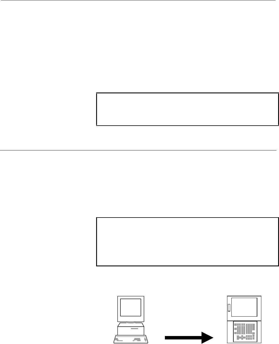
(1) A command based on screen selection/page key/soft key
operation is issued with the host software.
Personal computer on
the host side
Series 15i/16i/18i/21i
Screen selection
Page keys
Soft keys
Contents Summary of SERIES 15i-16i-18i-21i MODEL A Operators manual
- Page 1GE Fanuc Automation Europe Computer Numerical Controls Series 15i / 16i / 18i /21i/ Model A Remote Diagnosis Function Host Software Operators Manual B-63454EN/01 TECHNOLOGY AND MORE�
- Page 2B-63454EN/01 SAFETY PRECAUTIONS SAFETY PRECAUTIONS This manual includes safety precautions for protecting the user and preventing damage to the machine. Precautions are classified into Warnings and Cautions according to their bearing on safety. Also, supplementary information is described as Notes.
- Page 3
- Page 4B-63454EN/01 PREFACE PREFACE This manual descibes the following products. Product Name Abbreviation FANUC Series 15i-MODEL A Series 15i FANUC Series 16i-MODEL A Series 16i FANUC Series 18i-MODEL A Series 18i FANUC Series 21i-MODEL A Series 21i p-1�
- Page 5
- Page 6B-63454EN/01 CONTENTS SAFETY PRECAUTIONS ...................................................................................... s-1 PREFACE ................................................................................................................ p-1 1. OVERVIEW................................
- Page 7CONTENTS B-63454EN/01 4. OPERATION ...................................................................................................... 29 4.1 FUNCTION OVERVIEW ........................................................................................................ 30 4.1.1 Screen Configuration...
- Page 8B-63454EN/01 CONTENTS APPENDIX A. USABLE MODEM CARDS .............................................................................. 57 B. CNC PARAMETERS RELATED TO REMOTE DIAGNOSIS................... 58 c-3�
- Page 9
- Page 10B-63454EN/01 1. OVERVIEW 1 OVERVIEW -1-�
- Page 111. OVERVIEW B-63454EN/01 1.1 GENERAL With the remote diagnosis function, CNC data can be transferred between the FANUC Series 15i/16i/18i/21i and a personal computer, acting as a service terminal, through a telephone line. Modem Card (Note) Telephone line Personal computer Modem Series 15i/16i/18i/2
- Page 12B-63454EN/01 1. OVERVIEW 1.3 MODELS SUPPORTED This software runs under Windows95, Windows98, or Windows NT4.0(*1) on an IBM-PC/AT compatible machine. *1 This software runs under Windows NT4.0 including Microsoft Windows NT4.0 Service Pack 3 or above. 1.3.1 About this Software This software incorpora
- Page 131. OVERVIEW B-63454EN/01 1.4 FUNCTIONS The software provides the functions listed below. 1.4.1 Download Functions (CNC to Computer) (See also: Section 4.6) a. Display (0) CNC series and edition (21) Number of tool groups (1) Maintenance information (22) Number of tools (2) Printed circuit board (23)
- Page 14B-63454EN/01 1. OVERVIEW For the Series 15i (0) Maintenance information (5) Printed circuit board (1) All parameters information (2) All programs (6) System alarm (3) One program (7) Reception of signals in a (4) Operation history/alarm batch history 1.4.2 Upload Function (Computer to CNC) (See also
- Page 151. OVERVIEW B-63454EN/01 1.5 EXAMPLES OF EXECUTION Choose Phone and Dial, then enter the desired telephone number. 0123-45-6789 Clicking the OK button establishes a connection. Once a connection is established, the following screen appears: -6-�
- Page 16B-63454EN/01 1. OVERVIEW Choose Receive, Display, then (0) CNC Series and Edition. Then, the selected data is transferred to the host (in the upper-left part of the screen). CNC series and edition data is also displayed in the lower-left part of the screen. With the Series 16i/18i/21i, this informat
- Page 171. OVERVIEW B-63454EN/01 Clicking the GET Screen button transfers the display data for the current CNC screen. Choose Receive, Display, then (0) Mainte Info. Then, maintenance information is received (on the left side of the screen). -8-�
- Page 18B-63454EN/01 1. OVERVIEW Upon the completion of diagnosis, choose Phone and the Hang to break the connection. Choosing Phone and then Phone history allows the user to check the telephone call history. -9-�
- Page 192. INSTALLATION PROCEDURE B-63454EN/01 2 INSTALLATION PROCEDURE -10-�
- Page 20B-63454EN/01 2. INSTALLATION PROCEDURE 2.1 CAUTIONS ON INSTALLATION - At least 6.5MB of free hard disk space is required to install the host software. - To upgrade the host software, delete the existing "FANUC Remote Diagnosis," then install the new version. If a new version is installed without fir
- Page 212. INSTALLATION PROCEDURE B-63454EN/01 2.2 INSTALLATION (1) Insert the first floppy disk into the floppy disk drive, and then execute "Setup.exe" from the floppy disk. Then, the message shown below appears. (2) After a short while, the message below appears. Click the Next button to proceed to the n
- Page 22B-63454EN/01 2. INSTALLATION PROCEDURE (4) After a short while, the message below appears. Insert the second floppy disk into the drive, and then click the OK button. (5) Upon the normal completion of installation, the message below appears. Clicking the Finish button terminates the installation. (6
- Page 232. INSTALLATION PROCEDURE B-63454EN/01 2.3 UNINSTALLATION (1) Start Add/Remote Programs in the Control Panel. (2) Specify deletion of the application "FANUC Remote Diagnosis." -14-�
- Page 24B-63454EN/01 2. INSTALLATION PROCEDURE (3) The dialog box for deletion confirmation appears. Choose Yes. (4) The dialog box for confirming that files such as the OCX and DLL files may be deleted appears. Choose whether to delete these files. (5) Upon the completion of application deletion, the messa
- Page 253. CONNECTION B-63454EN/01 3 CONNECTION -16-�
- Page 26B-63454EN/01 3. CONNECTION 3.1 CONNECTION BETWEEN THE CNC AND TELEPHONE LINE 3.1.1 Connecting a Modem Card to the CNC For the Series 16i/18i/21i - After turning off the power to the CNC, insert the modem card into the slot on the front of the CNC’s LCD unit. - Turn on the power to the CNC. The modem
- Page 273. CONNECTION B-63454EN/01 WARNING It is dangerous to insert a modem card when the power to the CNC is on. An expected operation can occur. NOTE For an explanation of how to use the modem card, see the operator’s manuals provided with the modem card and mobile telephone. When a mobile telephone line
- Page 28B-63454EN/01 3. CONNECTION - CD signal turned on at all times - ER signal turned on at all times - Data flow control XON/XOFF - Automatic transmission speed adjustment enabled (to allow automatic adjustment for connection at a maximum allowable speed) - Command echo not used - Result code not used E
- Page 293. CONNECTION B-63454EN/01 - Command echo not used - Local echo not used - Result code not used Example of external modem setting In this example, the use of the following modem is assumed for command settings: Omron: ME3314B Connect the modem to the personal computer, then start the terminal softwa
- Page 30B-63454EN/01 3. CONNECTION 3.2 CONNECTION BETWEEN THE PERSONAL COMPUTER AND TELEPHONE LINE Make a connection as explained in the manuals provided with the personal computer and modem. -21-�
- Page 313. CONNECTION B-63454EN/01 3.3 CNC SETTING 3.3.1 Connecting a Modem Card to the CNC For the Series 16i/18i/21i Basically, no parameters need to be set. For transmission at a baud rate other than 9600 bps, make the following settings: - Bit 6 (MCB) of No. 0201 = 1 - No. 0203 = 1 to 12 (For details, s
- Page 32B-63454EN/01 3. CONNECTION When starting remote diagnosis, set bit 0 (RDG) of parameter No. 0002 to 1. Upon the completion of remote diagnosis, set bit 0 of parameter No. 0002 to 0. When bit 0 of No. 0002 = 1, the line status can be checked on the CNC screen by pressing the following keys in this or
- Page 333. CONNECTION B-63454EN/01 3.4 SETTING THE PERSONAL COMPUTER The user must choose Others and Setting comm for communication- related setting. For the Series 16i/18i/21i Set each item according to the parameters for the personal computer, telephone line, and CNC. (See also: Section 4.9.1) For the Ser
- Page 34B-63454EN/01 3. CONNECTION 3.5 LINE CONNECTION/DISCONNECTION 3.5.1 Line Connection (when Using a Modem Card) a) Making a connection for the first time Choose Phone and then Dial. Then, the following window appears: Enter the desired telephone number, then click the OK button to establish the connect
- Page 353. CONNECTION B-63454EN/01 3.5.3 Line Connection/Disconnection (when Connecting an External Modem Via the RS-232-C Interface) For the Series 16i/18i/21i A connection can be made/broken in the same way as when a modem card is used. (See also: Section 3.5.1) (See also: Section 3.5.2) Before making a c
- Page 36B-63454EN/01 3. CONNECTION 3.6 ACCESS RIGHT 3.6.1 About Access Right To access a CNC for which a password is set to protect the CNC machine tool information, the access right must be acquired using the password. Otherwise, the CNC information cannot be acquired. 3.6.2 Password Setting for the CNC Fo
- Page 373. CONNECTION B-63454EN/01 3.6.4 About Passwords Password 1 : Password 1: Enter a password for all remote diagnosis function services. If an entered password is unacceptable, the following dialog box is displayed when an attempt is made to make a connection, and the attempt to connect to the CNC is
- Page 38B-63454EN/01 4. OPERATION 4 OPERATION -29-�
- Page 394. OPERATION B-63454EN/01 4.1 FUNCTION OVERVIEW 4.1.1 Screen Configuration When the remote diagnosis host software is started, the following screen appears: C A B E F H G D A. Diagnosis data display screen : This area displays diagnosis data received from the CNC. B. CNC screen data display : This a
- Page 40B-63454EN/01 4. OPERATION 4.1.2 Pull-Down Menu The menus on the screen are configured as described below. For the Series 16i/18i/21i File Edit Phone Screen Receive Send Others Help File Print Prints the currently displayed host software screen data. US version > Switches the menu language and screen
- Page 414. OPERATION B-63454EN/01 Others Setting comm Makes settings related to the serial port. Folder setting Makes directory settings such as file input/output. Select Path > Chooses a CNC system. AutoGetScreen > Chooses whether to transfer screen data automatically. MDIkey > To be chosen when MDI key in
- Page 42B-63454EN/01 4. OPERATION Send Input > Selects the data to be sent to the CNC. File > Others Setting comm Makes settings related to the serial port. Folder setting Makes directory settings such as file input/output. Select Path > Not used AutoGetScreen > Chooses whether to transfer screen data autom
- Page 434. OPERATION B-63454EN/01 4.2 FILE MENU 4.2.1 Print The user can print the data currently displayed on the host software. NOTE The printer to be used needs to be set in Windows beforehand. 4.2.2 US version/Japanese version The user can select the language used, for example, for the host software men
- Page 44B-63454EN/01 4. OPERATION 4.3 EDIT MENU 4.3.1 Copy This menu item copies the selected data to the Windows clipboard. Right-clicking a selected range of data has the same effect. 4.3.2 Copy to file(I) Selected data can be output to a file. When this menu item is chosen, the file name selection dialog
- Page 454. OPERATION B-63454EN/01 4.4 PHONE MENU 4.4.1 Dial When this menu item is chosen, the following window appears: Enter the desired telephone number, then click the OK button to start the connection of the telephone line. NOTE The type of telephone line must be entered in the communication settings.
- Page 46B-63454EN/01 4. OPERATION (2) To set a new communication destination, choose the New button with the mouse. To modify an existing communication destination, choose the communication destination with the mouse, and the click the Properties button. Then, the following communication destination setting
- Page 474. OPERATION B-63454EN/01 Phone list NOTE Up to ten communication destinations are displayed on the menu. The order of communication destinations can be changed by clicking the UP/DOWN button in comm List. An item for which Add Menu List is not checked in the communication destination setting dialog
- Page 48B-63454EN/01 4. OPERATION 4.5 SCREEN SWITCHING The user can switch from one CNC screen to another. The Get Screen button is used to transfer the information of a switched screen. (See also: Section 4.1.3) For the Series 16i/18i/21i The items indicated below are displayed. Symbols [i], [M], and [T] o
- Page 494. OPERATION B-63454EN/01 SYSTEM - [I] DATA SERVER - PARAMETER MAINTENANCE - DIAGNOSE - [I] DATA SERVER MODE - PMC STORAGE - SYSTEM - [I] VGA COLOR SETTING - MEMORY - [I] PERIODICAL - PITCH ERROR MAINTENANCE DISP - SERVO SETTING - [I] MAINTENANCE - SPINDLE SETTING INFORMATION DISP - [i] C-SERV - [I]
- Page 50B-63454EN/01 4. OPERATION - PARAMETER - SYSTEM CONFIGURATION - PITCH ERROR - PMC COMPENSATION - SERVO SETTING - DIAGNOSIS - HPCC - DI/DO SIGNAL MONITOR - FSSB SETTING - PERIODICAL MAINTENANCE - CONTENTS OF MEMORY - MAINTENANCE INFORMATION MESSAGE - ALARM NOTE If a screen that cannot be displayed whi
- Page 514. OPERATION B-63454EN/01 (2) When the command is received, the CNC screen is switched. (3) CNC screen information is transferred to the host software by using the Get Screen button. GET SCREEN button Supplement : By choosing Others and AutoGetScreen, screen information can also be transferred autom
- Page 52B-63454EN/01 4. OPERATION Choose Screen, (3) SYSTEM, and then (4) SYSTEM, and then click the Get Screen button. The screen display changes to the following: -43-�
- Page 534. OPERATION B-63454EN/01 4.6 RECEIVE DATA 4.6.1 Receive (Display) The following data can be displayed by choosing Receive and then Display from the menu. (0) CNC series and edition (14) Absolute position (27) Cutter compensation number 1 (1) Maintenance information (15) Skip position (28) Cutter co
- Page 54B-63454EN/01 4. OPERATION Supplement: (5) Offset In addition to an offset number, an offset type must be set. Set an offset type as described below M series (machining center) Tool radius Tool length Wear 0 2 Figure 1 3 (Supplement) Set 0 when there is no tool radius/tool length distinction and no w
- Page 554. OPERATION B-63454EN/01 4.6.2 Receive (File) The data files listed below can be received by choosing Receive and File from the menu. (See also: Section 4.8.2) For the Series 16i/18i/21i (0) Maintenance information (1) All parameters (2) All programs (3) One program (4) Operation history (5) Alarm
- Page 56B-63454EN/01 4. OPERATION 4.7 SEND DATA 4.7.1 Send (Input) The following data can be entered by choosing Send and Input. (1) Parameter (4) Signal (2) Offset (5) Message (3) Macro variable Supplement: (2) Offset In addition to an offset number, an offset type needs to be set. Set an offset type as de
- Page 574. OPERATION B-63454EN/01 4.7.2 Send (File) The data described below can be sent by choosing Send and then File. (See also: Section 4.8.2) (1) All parameters (2) Program transmission (3) Program check NOTE 1 Before parameters can be entered or all parameters can be sent, the CNC must be placed in th
- Page 58B-63454EN/01 4. OPERATION 4.8 OTHER MENUS 4.8.1 Setting comm The following dialog box appears. Set each item as described below. For the Series 16i/18i/21i Port : Set a serial port number of the personal computer. BPS : Set the same transmission speed as that set on the CNC. DATA Bit : Set 8. Stop B
- Page 594. OPERATION B-63454EN/01 Flow Control : Set Xon/Xoff. Tone/Pulse : Specify the type of a telephone line to be connected to the host. Device : Set Modem when using a modem line. Set RS-232-C when making a direct connection to the CNC without using a modem. Note, however, that even if RS-232-C is set
- Page 60B-63454EN/01 4. OPERATION 4.8.3 Select Path For the Series 16i/18i/21i When diagnosing a multi-path CNC, select a path to be diagnosed. NOTE The loader cannot be diagnosed. This function can be used only with the Series 16i/18i/21i. 4.8.4 AutoGetScreen When On displayed on the pull-down menu is chos
- Page 614. OPERATION B-63454EN/01 4.8.7 MDIkey When On displayed on the pull-down menu is chosen, the input operation of the MDI keys other than the function keys and soft keys on the CNC can be performed through the full keyboard on the personal computer. (1) Select On. Then, the MDI button (A) appears. (2
- Page 62B-63454EN/01 4. OPERATION 4.9 HELP MENU 4.9.1 Version info This menu item displays the version of the host software. Example of display -53-�
- Page 63
- Page 64APPENDI�
- Page 65
- Page 66B-63454EN/01 APPENDIX A. USABLE MODEM CARDS A USABLE MODEM CARDS The operation of the cards listed below has been confirmed. (1) Cards manufactured by TDK Corp. Type Product name Remarks Modem card (analog) DF2814B For analog lines DF3314ES DF3314EX DF5600 DF5660 Digital communication card DVP3314S
- Page 67B. CNC PARAMETERS RELATED TO REMOTE DIAGNOSIS APPENDIX B-63454EN/01 B CNC PARAMETERS REMOTE DIAGNOSIS RELATED TO Parameters for the Series 16i/18i/21i #7 #6 #5 #4 #3 #2 #1 #0 0002 RDG [Data type] Bit # 0 RDG Remote diagnosis is: 0: Not performed. 1: Performed. When performing remote diagnosis using
- Page 68B-63454EN/01 APPENDIX B. CNC PARAMETERS RELATED TO REMOTE DIAGNOSIS 0203 Baud rate (for remote diagnosis) [Data type] Byte Set a baud rate to be used for data transfer in remote diagnosis according to the tables below. When an RS-232-C serial port is used Setting Baud rate (bps) Setting Baud rate (b
- Page 69B. CNC PARAMETERS RELATED TO REMOTE DIAGNOSIS APPENDIX B-63454EN/01 Password 1: Set a password for all remote diagnosis services. (If this password is not entered on the host (personal computer, for example), none of the remote diagnosis function services are available.) Password 2: Set a password f
- Page 70B-63454EN/01 APPENDIX B. CNC PARAMETERS RELATED TO REMOTE DIAGNOSIS 0000 RDN EIA NCR ISP [Input type] Setting input [Data type] Bit #2 ISP 0: ISO codes includes a parity bit. 1: ISO code does not includes a parity bit. The parity bit of ISO code is channel 8 of punched tape. When performing remote d
- Page 71B. CNC PARAMETERS RELATED TO REMOTE DIAGNOSIS APPENDIX B-63454EN/01 [Data type] Integer [Valid data range] 0 to 16 Set the interface number of an input device for background. When performing remote diagnosis, set this bit to 12. 0023 Interface number of output device for background [Input type] Sett
- Page 72B-63454EN/01 APPENDIX B. CNC PARAMETERS RELATED TO REMOTE DIAGNOSIS [Data type] Integer [Valid data range] 0 to 99999999 Parameter No. 0042, No. 0044, and No. 0046 above are used to set passwords for using the remote diagnosis function. With the remote diagnosis function, the passwords described bel
- Page 73B. CNC PARAMETERS RELATED TO REMOTE DIAGNOSIS APPENDIX B-63454EN/01 Set the device number of a reader/punch connected to the JD5A connector. In parameters No. 5100 through No. 5162, set the specification numbers corresponding to reader/punch device numbers 1 through 6. 5002 Device number of a reader
- Page 74B-63454EN/01 APPENDIX B. CNC PARAMETERS RELATED TO REMOTE DIAGNOSIS Specification No. Reader/punch specification 1 Control codes (DC1-DC4) are used. A feed code is output with the punch. 2 Control codes (DC1-DC4) are not used. A feed code is output with the punch. 3 Control codes (DC1-DC4) are used.
- Page 75B. CNC PARAMETERS RELATED TO REMOTE DIAGNOSIS APPENDIX B-63454EN/01 5132 Baud rate of the reader/punch corresponding to device number 3 5142 Baud rate of the reader/punch corresponding to device number 4 5152 Baud rate of the reader/punch corresponding to device number 5 5162 Baud rate of the reader
- Page 76B-63454EN/01 INDEX FUNCTIONS 4 A About Access Right 27 H About Passwords 28 Hang 36 About this Software 3 HELP MENU 53 ACCESS RIGHT 27 AutoGetScreen 51 I C INSTALLATION PROCEDURE 10 INSTALLATION 12 CAUTIONS ON INSTALLATION 11 CNC MDI Key(C) 51 K CNC PARAMETERS RELATED TO REMOTE DIAGNOSIS 58 Keyfree(
- Page 77INDEX B-63454EN/01 Phone List, comm List 36 PHONE MENU 36 Print 34 Pull-Down Menu 31 R Receive (Display) 44 Receive (File) 46 RECEIVE DATA 44 S Screen Configuration 30 SCREEN SWITCHING 39 Select all 35 Select Path 51 select Range 35 Send (File) 48 Send (Input) 47 SEND DATA 47 Setting comm 49 SETTING
- Page 78Revision Record FANUC Series 15i/16i/18i/21i-MODEL A Remote Diagnostic Function Host Software (For Windows) OPERATOR’S MANUAL (B-63454EN) 01 Dec.,’99 Edition Date Contents Edition Date Contents
- Page 79