Signal processing and parameter setting for Machine Protection Function at Power Failure (B-65162E/03-10) Supplement to Manual Page 2
Supplement to Manual
01
Ed.
1999.08.03
Date
S.Hanyu
Name
Newly designed
Detail of modification
Subject
Spec.
Signal processing and parameter setting
for Machine Protection Function
at Power Failure
B-65162E/03-10
FANUC LTD
Page
2/ 7
Signal processing and parameter setting
for Machine Protection Function at Power Failure
In Machine Protection Function at Power Failure, CNC performs the machine protection control by the power
failure detection signal output from Power Failure Backup Module after the power failure occurs. This document
explains about the signal processing and the parameter setting for Machine Protection Function at Power Failure.
About the specification and the connection of Power Failure Backup Module, refer to “Power Failure Backup
Module Description” B-65162/03-01 (without control power backup function), B-65162/03-08 (with control power
backup function).
1. Retract Function at Power Failure
This function is to retract the tool from the work keeping the tool and the work synchronized in case that the
power failure occurs during synchronized operation. To use this function some Sub Module C are necessary in
addition to Power Failure Backup Module. Refer to “How to define the number of Sub Module C” (B-65162/03-
04).
The retraction is controlled by CNC retract signal (whose address varies with the cutting mode), which is
controlled by the power failure detection signal (*PFL) output from Power Failure Backup Module. The PMC
programming for the retraction should be on the first level (8msec), so as to reduce the energy loss before the
retraction starts after the power failure occurs.
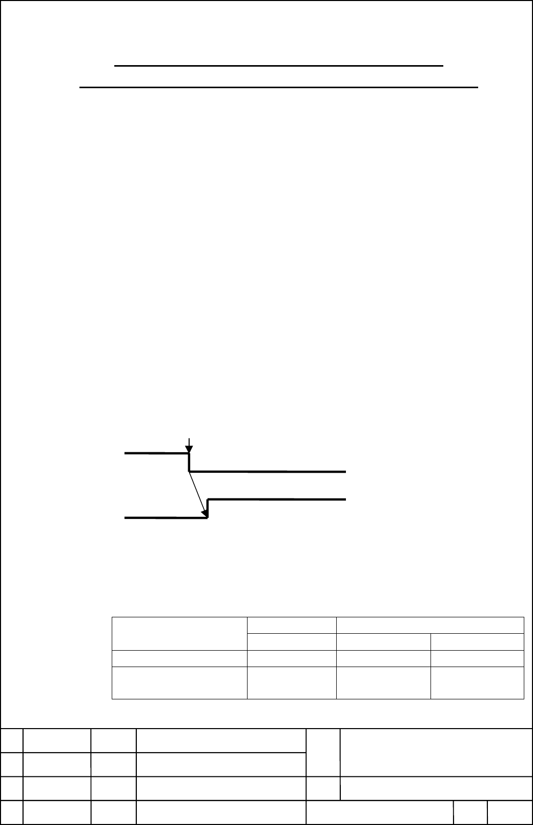
1-1 ELECTRIC GEAR BOX, SIMPLE ELECTRIC GEAR BOX, or HOBBING MACHINE FUNCTION
The retraction is controlled by Retract signal (RTRCT). Set RTRCT to “1” when Power failure detection
signal (*PFL) changes from “1” to “0”
Detect power failure
*PFL
RTRCT
*PFL: Power failure detection signal.
Output from the connector CX16 on Power Failure Backup Module.
RTRCT: Retract signal.
Performs retraction for the axis specified with a parameter when the signal is set to “1”.
The retract speed and amount of retraction are specified with the following parameters.
Signal address Parameter number
CNC RTRCT Retract speed Retract amount
FS15i, FS15-B G042 #4 No.7795 No.7796
FS16i/18i
FS16-B/18-B/16-C/18-C
G066 #4 No.7740 No.7741
Refer to Connection Manual (Function) and Parameter Manual of each CNC in detail.
Contents Summary of Signal processing and parameter setting for Machine Protection Function at Power Failure (B-65162E/03-10) Supplement to Manual
- Page 1POWER FAILURE BACK-UP MODULE DESCRIPTIONS 1.Type of applied technical documents Name FANUC SERVO AMPLIFIER a series DESCRIPTIONS Spec.No./Ver. B-65162E/03 2.Summary of change Group Name / Outline New,Add Applicable Correct,Del Date Basic Function Signal processing and parameter setting Addition Aug.
- Page 2Signal processing and parameter setting for Machine Protection Function at Power Failure In Machine Protection Function at Power Failure, CNC performs the machine protection control by the power failure detection signal output from Power Failure Backup Module after the power failure occurs. This doc
- Page 31-2 HIGH SPEED CYCLE CUTTING High-speed cycle machine retracting function is needed. The retraction is controlled by High-speed cycle machine retracting signal (HSRT). Set HSRT to “1” when Power failure detection signal (*PFL) changes from “1” to “0” Detect power failure *PFL HSRT *PFL: Power failur
- Page 41-3 The other synchronous cutting mode General purpose retract function is needed. The retraction is controlled by Retract signal (RTRCT) as same signal as Electrical gear box function. Set RTRCT to “1” when Power failure detection signal (*PFL) changes from “1” to “0” Detect power failure *PFL RTRC
- Page 52. Stop Distance Reduction Function at Power Failure This function is to stop the feed axes in the equal time constant with the normal operation to prevent the machine being damaged by over-running in case that the power failure occurs during the rapid traverse. It is possible to stop the spindle mo
- Page 6Note) When brake control is applied for a two- or three-axis amplifier, set the brake control parameters for all the axes to be controlled. If an alarm is generated for any of axes connected to the two- or three-axis amplifier, brake control does not operate effectively. Signal processing and parame
- Page 72 -2 Spindle axes stop control at power failure Set the spindle control signal *ESPA (*ESPB) to “0” when Power failure detection signal (*PFL) changes from “1” to “0”. Detect power failure *PFL *ESPA (*ESPB) *PFL: Power failure detection signal. Output from the connector CX16 on Power Failure Backup
- Page 83. Gravity-axis Electrical Brake Function at Power Failure This function is to keep the position of the vertical axis electrically until the mechanical brake of the vertical axis works when the power failure occurs and to prevent the vertical axis from dropping. Set the parameters of Brake Control F