Signal processing and parameter setting for Machine Protection Function at Power Failure (B-65162E/03-10) Supplement to Manual Page 8
Supplement to Manual
01
Ed.
1999.08.03
Date
S.Hanyu
Name
Newly designed
Detail of modification
Subject
Spec.
Signal processing and parameter setting
for Machine Protection Function
at Power Failure
B-65162E/03-10
FANUC LTD
Page
8/ 7
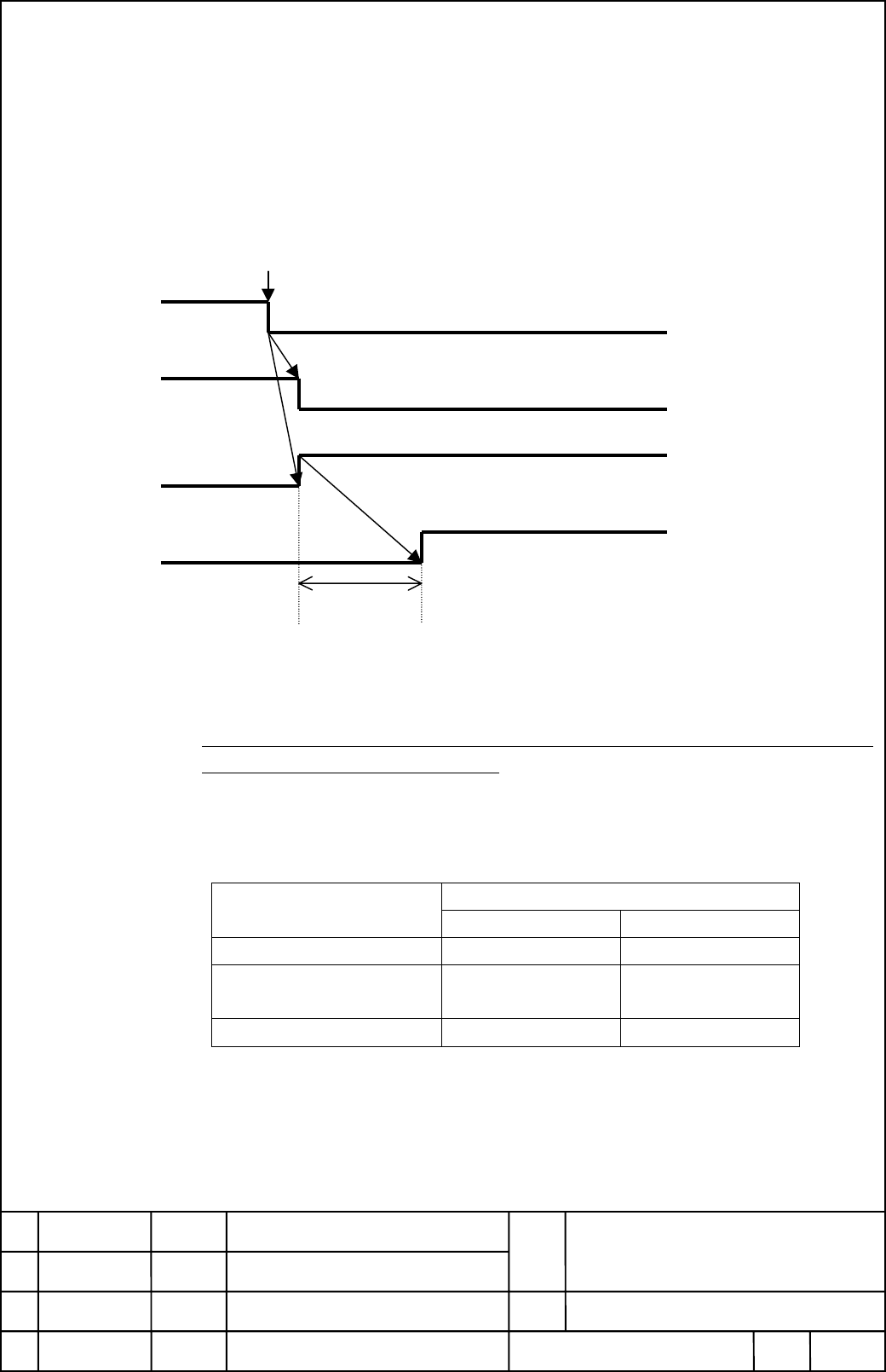
3. Gravity-axis Electrical Brake Function at Power Failure
This function is to keep the position of the vertical axis electrically until the mechanical brake of the vertical axis
works when the power failure occurs and to prevent the vertical axis from dropping.
Set the parameters of Brake Control Function (Servo basic function), and set the emergency stop signal (*ESP)
of CNC to “0” when Power failure detection signal (*PFL) changes from “1” to “0”. And put on the brake of the
vertical axis simultaneously.
Detect power failure
*PFL
*ESP
Relay for Brake
Brake Brake works.
delay time Td
*PFL: Power failure detection signal.
Output from the connector CX16 on Power Failure Backup Module.
*ESP: Emergency stop signal of CNC (See 2-1)
The signal operated by Power failure detection signal (*PFL) is CNC emergency stop
signal, not PSM emergency stop signal.
Parameter setting
(1) BRKC: “1” (The brake control function is used)
(2) Brake control timer: Set a time (Td) until the brake starts operating (about 100msec)
Parameter number
CNC BRKC Brake control timer
FS15i, FS15-A, FS15-B No.1883 #6 No.1976
FS16i/18i/21i
FS16/18/20, Power Mate
No.2005 #6 No.2083
FS0-C No.8X05 #6 No.8X83
Refer to PARAMETER MANUAL (B-65150/03) in detail.
Note) When brake control is applied for a two- or three-axis amplifier, set the brake control
parameters for all the axes to be controlled. If an alarm is generated for any of axes
connected to the two- or three-axis amplifier, brake control does not operate effectively.
Contents Summary of Signal processing and parameter setting for Machine Protection Function at Power Failure (B-65162E/03-10) Supplement to Manual
- Page 1POWER FAILURE BACK-UP MODULE DESCRIPTIONS 1.Type of applied technical documents Name FANUC SERVO AMPLIFIER a series DESCRIPTIONS Spec.No./Ver. B-65162E/03 2.Summary of change Group Name / Outline New,Add Applicable Correct,Del Date Basic Function Signal processing and parameter setting Addition Aug.
- Page 2Signal processing and parameter setting for Machine Protection Function at Power Failure In Machine Protection Function at Power Failure, CNC performs the machine protection control by the power failure detection signal output from Power Failure Backup Module after the power failure occurs. This doc
- Page 31-2 HIGH SPEED CYCLE CUTTING High-speed cycle machine retracting function is needed. The retraction is controlled by High-speed cycle machine retracting signal (HSRT). Set HSRT to “1” when Power failure detection signal (*PFL) changes from “1” to “0” Detect power failure *PFL HSRT *PFL: Power failur
- Page 41-3 The other synchronous cutting mode General purpose retract function is needed. The retraction is controlled by Retract signal (RTRCT) as same signal as Electrical gear box function. Set RTRCT to “1” when Power failure detection signal (*PFL) changes from “1” to “0” Detect power failure *PFL RTRC
- Page 52. Stop Distance Reduction Function at Power Failure This function is to stop the feed axes in the equal time constant with the normal operation to prevent the machine being damaged by over-running in case that the power failure occurs during the rapid traverse. It is possible to stop the spindle mo
- Page 6Note) When brake control is applied for a two- or three-axis amplifier, set the brake control parameters for all the axes to be controlled. If an alarm is generated for any of axes connected to the two- or three-axis amplifier, brake control does not operate effectively. Signal processing and parame
- Page 72 -2 Spindle axes stop control at power failure Set the spindle control signal *ESPA (*ESPB) to “0” when Power failure detection signal (*PFL) changes from “1” to “0”. Detect power failure *PFL *ESPA (*ESPB) *PFL: Power failure detection signal. Output from the connector CX16 on Power Failure Backup
- Page 83. Gravity-axis Electrical Brake Function at Power Failure This function is to keep the position of the vertical axis electrically until the mechanical brake of the vertical axis works when the power failure occurs and to prevent the vertical axis from dropping. Set the parameters of Brake Control F