Notice of the revision of Digital Servo ROM 90A7 series Additional Manual Page 50
Additional Manual
Title 9083 / 9087 / 90A3 / 90A7
Learning Control Operator’s Manual
03 '00.06.07 N.Sonoda Qualified 2'nd issue Draw No.
02 ’99.01.14 K.Maeda Qualified 1’st issue
A - 63639E - 034
01 ’97.12.08 K.Maeda Newly designed Sheet 048
Edit Date Design Description / 070
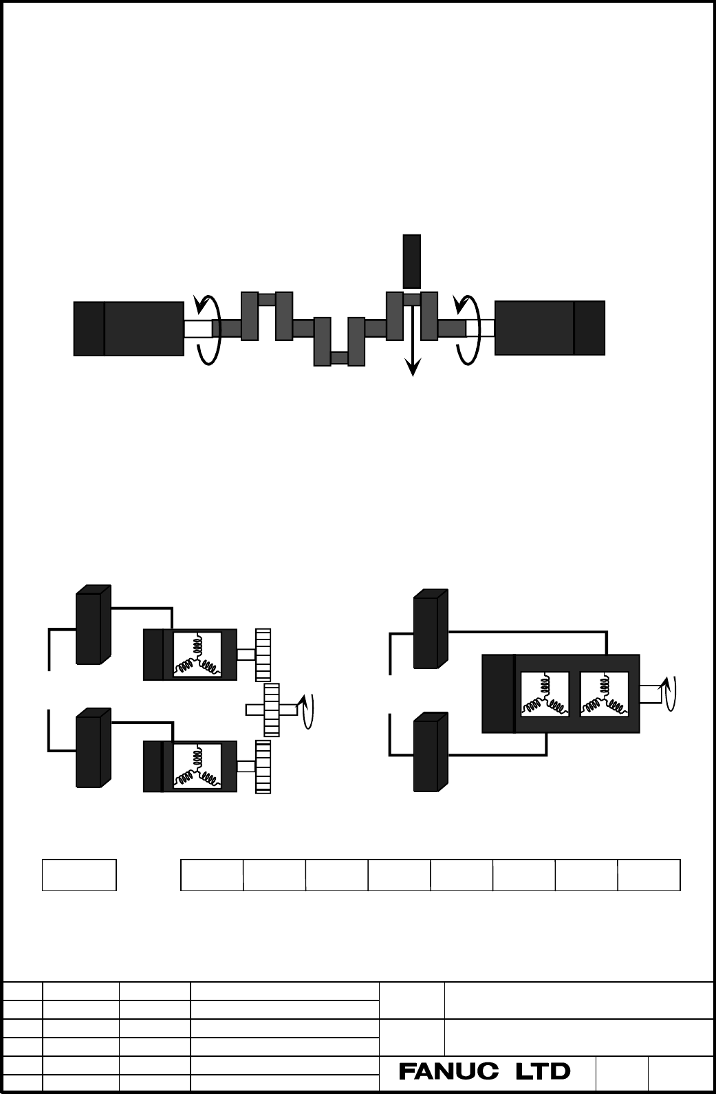
7.6 Tandem Learning control function (only 90A7 series)
7.6.1 Summary
Tandem Learning control is a Learning control combined with Tandem control. By means that two motors are
controlled as one axis, and Learning control is added, this function achieves high precision processing in the
special applications.
1) Position Tandem Learning control
Merit : To Achieve high accuracy to learn the position deviation with both sides of long
workpiece which have weak stiffness chucked and driven by two motors.
Applicable machine : Cam grinder, Crank shaft grinder, and etc
2) Torque tandem Learning control
Merit : Large torque of double motor can achieve leaning of the position deviation due to
large cutting torque.
α 400 or α300 requires torque tandem in spite of single motor,
because they have double coils in one motor and use two amplifiers. We call this
“
double coil tandem control” as a special case of torque tandem.
Applicable machine : Helical gear shaper without helical slide, Helical broach machine, Accurate press, etc
7.6.2 Parameters
TANDEM Tandem control (Power must be off) (NC Option)
0 : Available.
1 : Not available
In case of Torque Tandem Learning control that main and sub motor don’t disconnect mechanically, set
Cutting force
Grinder
MotorMotor
Work
Servo
Large
torque
Amplifier
Motor
Motor
Amplifier
Motor
Amplifier
Servo
Amplifier
Large
torque
1817
TANDEM
Contents Summary of Notice of the revision of Digital Servo ROM 90A7 series Additional Manual
- Page 1Notice of the revision of Digital Servo ROM 90A7 series 1. Type of applied documents Name FANUC Digital AC SERVO 9083 / 9087 / 90A3 / 90A7 series Operator’s manual Spec.No./Ver. A-63639E-034/03 2. Summary of Change Group Name / Outline New, Add Applicable Correct, Del Date Basic Function 1. The exte
- Page 2Notice of the revision of Digital Servo ROM 90A7 series We report the revision of Digital Servo ROM 90A7 series. 1. Update Edition ROM series Old edition New edition Available CNC 90A7 001A 001B FS16i,18i (for Self-Learning function) 2. Content of change a) The extension of Learning period Maximum L
- Page 3FANUC AC SERVO SOFTWARE 9083 / 9087 Series 90A3 / 90A7 Series LEARNING FUNCTION Operator’s Manual 1. Overview 2. System Configuration 3. Application Examples 4. Explanation of Learning Control 5. Servo parameters 6. Learning Control functions 7. Functions detail 8. Adjustment 9. Attentions Appendix
- Page 4Contents 1. Overview ……………………………………………………………………………………. 3 2. System Configuration ………..…………………………………………….…….………... 5 3. Application Examples ………..…………………………………………….…….………... 6 3.1 Lead Cutting ……..……………………………………………………….…….…….. 6 3.2 Piston Lathe …….…..…………………………………………………….…….…..… 7 3.3 Cam grinder ……
- Page 51. Overview This manual describes the only special servo functions and parameters relating to High-speed Cutting and Learning function used in FANUC Digital AC Servo. With respect to the information of the standard servo function for general cutting tools, you can get it from FANUC AC SERVO MOTOR α
- Page 6(Note 1) A High-speed axis or a Learning axis occupies one Servo CPU, and can not coexist with another axis. A High-speed axis or a Learning axis must be allocated to L-axis (odd number axis). A High-speed axis is the axis supporting High-speed Interface (G05 activates the interface). • High-speed a
- Page 72. System Configuration High-speed cutting (G05) can be achieved using three below cases. Fig.2-1 shows a system configuration. (1) Memory operation by “High speed cycle cutting” a) To produce cutting data by Open CNC or personal computer and down load to P-code area of CNC. b) To produce cutting da
- Page 83. Application example 3.1 Lead cutting machine Double slide mechanism Z axis X axis Y axis Byte 1 Byte 2 Cutter movement Zoom Up B C axis (cross section) A Tape driving surface : A Tape driving surface Lead surface : B Fig. 3.1.1 Cnfigulation example of Lead Cutting Machine (1) The tape running sur
- Page 93.2 Piston Lathe Piston axis Y axis Oval cross Section Piston Work X axis Double slide mechanism Z axis Fig. 3.2.1 Configuration example of piston lathe * Cutting Sequence (1) The piston outside is cut by rotating the spindle to move the tool back and forth along the Y axis. By feeding the tool alon
- Page 103.3 Cam Grinding Machine Profile 1 Profile 3 A A - A' cross section C axis Profile 2 Profile 4 CAM work Grinder Grinding tool A' X axis Spiral grinding CAM work Z axis Single slide mechanism Fig. 3.3.1 Example of Configuration of Cam Grinding Machine. * Grinding Sequence (1) The cam form is ground s
- Page 111'st cutting step 2'nd cutting step 3'rd cutting step G05 start G05 end Approach LESTTM L2 PRIOD2 L1 X axis L1 PRIOD Learning start The 2'nd Repetitive count Repetitive count RPTCT2 RPTCT 1/L1 Average speed C axis 1/ L2 Average speed L1 , L2 : C axis rotation period Fig. 3.3.3 Cutting Chart (when pr
- Page 124. Explanation of Learning Control 4.1 Summary of Learning Control FANUC Learning function Learning control Preview Repetitive control Learning Learning Adaptive Preview controller controller controller l What is “Learning Function” ? It is a function for realizing high-speed and high-precision cutt
- Page 134.2 Learning Control Learning controller Suspension Continuation G0(s) + Command 1 Kp + + s - Position Error Position Motor Gain Position feedback [ Merit ] l Replacing the mechanical cam tracing method with the electric master cam. l Minimized position error for repetitive command with specified pe
- Page 14the command within one profile gradually change due to cutting feed, such as the case of single slide mechanism. (Note) Compensation data mode means that compensation data is not clear at G05 finish. Both Suspension and Continuation mode clear it every time G05 finish. And it takes some times to cle
- Page 155. Servo parameters 5.1 Setting parameters (Series 16) 5.1.1 Setting CNC parameters CNC parameters setting related to High-speed Cutting are explained. According to the detail, refer to the “FANUC Series 16 / 18 manual”. (1) Set the following parameter. • No.1004 (Bit type) B1=1, B0=1 (IS-C : 0.1µm
- Page 16(Example 2) In the following configuration, set 1, 2, 3 and 5 for No.1023. Axis name Servo axis number st X axis 1 axis nd Z axis 2 axis rd C axis 3 axis (Learning axis) th Y axis 5 axis (High speed axis) rd th (Note) In case setting Learning axis for the 3 axis, you can not allocate a normal axis f
- Page 175.1.3 Setting servo parameters (In case semi-closed and 0.1µm :Serial pulse coder A, α1000 or α64) According to the detail, refer to “AC SERVO MOTOR α series Parameter Manual”. Because all servo parameters (No.2000 - No.2269) are axis type, you should set it for each axis. (1) Set the following para
- Page 185.1.4 Caution in case of servo parameter setting for High-speed axis High-speed axis is the axis that can accept the high-speed distribution data from CNC. In case that you set a High-speed distribution axis (No.7505#0 = 1) on CNC side, you must set certainly High-speed axis bit (No.2005#4 = 1) on c
- Page 195.2 Setting High gain parameter In case of using Learning control for Cam grinder etc, and the position error does not converge due to the influence of disturbance, it is recommended to use the High gain setting. Refer to “Appendix 3. Parameter table for Learning control”. (Note) This is not the cas
- Page 205.3 Servo parameters List The following parameters number are for FS16. The shaded parameters are detailed in this manual. B7 B6 B5 B4 B3 B2 B1 B0 2000 PGEX DGPR PLC0 2002 2003 VOFS OVSC BLEN NPSP PIEN OBEN TGAL 2004 DLY1 DLY0 TIB1 DLY2 TRW1 TRW0 TIB0 TIA0 2005 SFCM BRKC HSPEED 36RPC FEED 2006 RIPPL
- Page 212067 FILTER Tcmd filter coefficient 2110 MGSTCM Magnetic saturation compensation coefficient 9083/A 2113 Center frequency for resonance eliminate filter (Hz) 90A3/B 2175 RSHFTL R-phase current offset compensation coefficient 9083/B 2176 SSHFTL S-phase current offset compensation coefficient 9083/B 2
- Page 222246 GODMX Maximum order of Gx 2247 GODMN Minimum order of Gx 2248 GCOEF / EXGXK1 Max. coefficient of Gx / Coefficient 1 of expanded Gx 2249 EXGXK2 Min. coefficient of Gx / Coefficient 2 of expanded Gx 2250 EXGXK3 Coefficient 3 of expanded Gx 2251 EXGXK4 Coefficient 4 of expanded Gx 2252 EXGXK5 Coef
- Page 235.4 Servo parameter detail If not necessary, Don’t change the standard parameters of Auto loading. In case of specifying Series and edition, you can use the function from that edition or later. 2003 VOFS OVSC BLEN NPSP PIEN OBEN TGAL PIEN Velocity loop is 1 : PI control 0 : IP control 2005 SFCM BRKC
- Page 242200 PK2VSF PFBSFT OVRNSP 2201 VOCECM RUNLVL CROF PK2VSF Velocity proportional weight (9087/01 or later) 1 : 1/4 ♦ There is a possibility of causing Parameter alarm in case of large 0 : Normal setting Load inertia ratio. In this case, set to 1. PFBSFT Conversion coefficient of hunting control (No.20
- Page 25No.2067 = 4096 × exp(-2π×100×0.001) = 2185 (Example 2) Case of high gain axis (τ = 0.5msec) and fc = 100 [Hz] No.2067 = 4096 × exp(-2π×100×0.0005) = 2992 (Example 3) Case of high speed axis (αL6, αL9, τ = 125µsec) and fc = 100 [Hz] No.2067 = 4096 × exp(-2π×100×0.000125) = 3787 2110 MSGTCM Magnetic s
- Page 266. Learning Control function 6.1 Learning Control parameters 2007 ILMTRL STPRED ADERSL VCMDCL UNTSL TRASMT ADAPT VELHSP 2008 INVSYS ICM SLEN LCON EXGX MSCHK (TNDM) LSTP SLEN Learning control (Option) is 1 : Available. ♦ If you change SLEN, you must turn off and on CNC. 0 : Not available. (Power must
- Page 27because of no need to power off compared to the way of disabling SLEN (No.2008#0). st 2243 PRIOD 1 Learning period (Command period) [msec] Data range : 15 to 16000 ( If No.2007#3 = 1, to 32000) * 90A7/B is up to 32000. You should set Command data period PRIOD corresponding to spindle rotation speed
- Page 28Learning result is memorized by each profile. 2234 LESTTM Learning start time [msec] Data range : 0 to 16000 (When No.2007#3 = 1, to 32000 [Velocity sampling time]) Standard : 0 Learning control starts usually from non-zero command after the High-speed cycle cutting (G05) starts. If this parameter i
- Page 292246 GODMX Maximum order of Gx Data range : 0 to 20 Standard : Refer to Appendix 3. Parameter table for Learning control. 2247 GODMN Minimum order of Gx Data range : 0 to GODMX Standard : Refer to Appendix 3. Parameter table for Learning control. (Note) In case of Expanded Gx being enable (No.2008#3
- Page 30Profile 1 Profile 5 Com m and Com m and G05 G05 Learning Controller W hen IC M=0, MC is Mem ory clear switch (MC) available at tim e of G05 finish. Profile 1 (Mem ory) Low pass filter Profile 2 + No.2244 (Mem ory) All profile num ber No.2264 F(z-1) + Suspension (LCO N) Profile 5 (Mem ory) Dynam ic c
- Page 316.2 Adaptive Preview Control Parameters 2007 ILMTRL ADERSL VCMDCL UNTSL TRASMT ADAPT VELHSP 2008 INVSYS ICM SLEN LCON EXGX MSCHK (TNDM) LSTP INVSYS Adaptive Preview Control is 1 : Available. ♦ CNC software option is necessary 0 : Not available. (Note) If you use this function, you must set to 1 for
- Page 322256 FORW1 - − Feed forward coefficient W1 - W6 2261 FORW6 Data range : -32768 to 32767 Standard : 0 Feed forward coefficients FORWi are usually decided by Adaptive mode. Also you can calculate by the following expression. fi PULCO SDMR2 1 FORWi = × 2 16 × × × 100 PPLS SDMR1 80 fi is feed forward co
- Page 337. Functions detail 7.1 Servo trace function Servo Trace function transmits inner servo data to CNC program area for analyzing the servo variables such as the actual motor position or the torque command. You can output servo data to a personal computer through RS232C. You can do the same analysis by
- Page 342027 DTKND Kinds of trace data B0 : Position feedback (Position loop) B1 : Motion command (Position loop) B2 : Position Error (Position loop) B3 : Velocity command (Position loop) ∗B4 : Σ Motion command (Position loop) ∗B5 : Σ Position feedback (Position loop) B6 : Torque command (Velocity loop) ∗∗B
- Page 357.1.3 Operation of Servo trace (1) How to open Servo trace screen A-1 Push SYSTEM key on MDI. A-2 Push [ ] of Soft-key, and push [SV-PRM] of soft-key. A-3 Push [SV.TRC] of soft-key, and push [(OPRT)]. Then [TRACE] and [TRNSF] of soft-key display in Servo trace screen. (Note) [TRNSF] displays only in
- Page 36(2) Case of Piston lathe (semi-closed) A-1 Select Σ Motion command (B4) and Σ Position feedback (B8) as the kind of trace data. (No.2027 set to 272.) And get these data in your computer by tracing these data. A-2 The 1st data is Σ Motion command. The next N data are Σ Position feedback data. These o
- Page 377.2 Learning Memory expanded function Learning Memory expanded function allows the application to take advantage of many profiles up to Max. Profile number and many learning steps up to Max. Learning step number as the following table. (Option) This function is available in the following edition. •
- Page 387.2.2 Processing flow Grinding start ∗ ♦ When old spec. (LEBFEX = 0), you Set Total profile number according to camshaft G10 don’t use the marked “∗”. ∗ Did you change Total profile number ? Yes ∗ No ♦ When Total profile number is changed or Clear out all learning buffer Compensation data mode is in
- Page 397.2.3 Cautions Learning memory expanded function realize the specification by the learning memory to alter a sample rate. It have automatically the sampler gather the data roughly every 2 to Nth power in case of long Learning period or many profiles and Learning steps, because of which case many com
- Page 407.3 Learning Data Transmission Function 7.3.1 Overview For the purpose of preserving the servo learning data after NC powered off, The learning data can be preserved in the hard disk device (HD), which store the learning data through CNC and load it the memory of servo control. (Learning data transm
- Page 417.3.4 How to transmit Learning Data l To SAVE Learning Data (Servo → HD) 1) All of the first, you must confirm the error of Learning control converged well. 2) Set No.2233 of Profile number to zero in case of the lump deal method. Check No.2264 of Total Profile number beforehand. Note) You can SAVE
- Page 42l To LOAD Learning Data (HD → Servo ) 1) Set No.2233 of the Profile number to zero in case of the lump deal method. Learning Data saved by the lump deal method must be loaded by the lump deal method. Check No.2264 of the total number of Profile to be same value as saved before.(It must be so!) l Set
- Page 43Examples (1) Correspondence with processing program and Work Total profile number O0001 ; Profile i Profile j G10 L50 ; C axis N2264 P (Axis) R (Total profile number) ; G11 ; G10 L50 ; Grinding N2233 P (Axis) R (Profile number i) ; X axis CAM work N2242 P (Axis) R (Learning count) ; N2243 P (
- Page 44(2) Example of file management by Partial deal method We describe the case that Work 1 and Work 2 on right figure is processed in that order. This case suppose PC has already Learning data in the HD of A,B,C,D,E,F. A B C D 1) At first you should fix Total profile number PRFALL to 4 . 2) According to
- Page 457.4 Ultra high precision Velocity feedback function (Separate semi-closed) 7.4.1 Summary In 9087 series, Ultra high precision Velocity feedback (Abbreviation : separate semi-closed) function can be realized by using the rotary encoder RON8xx (36000 slits) or RON7xx(18000 slits) made by Heiden-Hain a
- Page 46(3) Series 16i-A (FSSB I/F) Refer to following 7.4.6. 7.4.3 Parameter setting concerned to Position feedback The following parameter must be set for this function available. • Set No.2006#3 to 1. Ultra high precision velocity feedback is available. (Note) Power must be OFF. This is valid for only Hi
- Page 477.4.5 Cautions 1) Rotation direction of Rotary encoder • Because the signal from Rotary encoder is used as the velocity feedback, connect the A-phase and B- phase as positive feedback returns when Rotary encoder rotates the CCW (Counter Clock-wise) direction from view of Motor shaft side. You can ma
- Page 487.4.6 High resolution encoder RCN723F Heidenhain absolute encoder RCN723F is available in 90A7/B for i-series CNC. This encoder has 223 resolution. 1) Cable connection method RCN723F CNC AMP Motor i-series SVM FSSB JF 2) Parameter setting This encoder is applied as 7,200,000 pulse / revolution becau
- Page 497.5 Torsion compensation during high speed cycle cutting function This function adds the compensation at the point of the command reversing sign during high speed I/F mode (G05), This function is useful for the case that the reverse point of work piece has sharp drop because it is easy to bend for t
- Page 507.6 Tandem Learning control function (only 90A7 series) 7.6.1 Summary Tandem Learning control is a Learning control combined with Tandem control. By means that two motors are controlled as one axis, and Learning control is added, this function achieves high precision processing in the special applic
- Page 51this bit to 1. But in case of the application that both motors disconnect by the operator such as double side chucking, set this bit to 0 to enable “Sub axis separation function” exclusively or “Synchronous Learning function”. Of course the double coil tandem requires TANDEM to be one due to the for
- Page 522087 Preload torque (Note) Set for both Main and Sub axes. Set zero in case of double coil tandem or the position tandem learning control. Set a value that is as small as possible but greater than the static friction torque. A set preload torque is applied to each motor at all times. So, set a value
- Page 53“FANUC Series 16i-Model A Connection Manual (Function)” (B-63003EN). In addition, Coupling flag is available from the following CNC software edition. B0F1/20 (FS16i-MA), B1F1/18 (FS16i-TA), BDF1/20 (FS16i-MA), BEF1/18 (FS16i-TA) 7.6.4 The others 1) In condition Simple synchronous control is availabl
- Page 549. Cautions 9-1. ITP Delay Alarm In case that CNC operation is delayed during G05 (High speed cycle cutting or High speed DNC operation), work piece is not processed normally. For this reason, High speed axis checks this delay (ITP delay) during G05. You can confirm that whether this delay happened
- Page 559-5. Full-closed system In series 16 or 18 (Model B or C), Servo axis module (A20B-2902-0061) for Learning control does not support separate serial pulse coder. You should use the scale or encoder of A/B phase type. In addition, Servo axis module for standard (A20B-2092-0070) does not have this rest
- Page 56Appendix 1. Notes on the order 1-1. Servo axis Module (series 16) or Servo axis Card (i-series) You must specify the Main CPU board for Learning Control in series 16 or series 18. • 2 axes A02B-022x-H004 • 4 axes A02B-022x-H005 • 4 axes A02B-022x-H006 (Note) Servo Module : A20B-2902-0061 You must sp
- Page 57Appendix 2. Making method for cutting data PROFILE 2 PROFILE 1 X-axis RIFT C-axis ANGLE MMC or Personal Computer X-axis RIFT C-axis ANGLE 1cycle 1cycle P10004 BINARY DATA P10001 X-axis Command per C-axis Command per Distribution cycle Distribution cycle ∗ Distribution cycle = 0.5msec, 1msec, 2msec D
- Page 58Appendix 3. Parameter table for Learning control Standard parameter setting for Learning control 1/4 Motor Model αL9 αL9 αL9 αL6 αL6 Motor Spec. 0564 0564 0564 0562 0562 Motor ID. 74 74 (74) 75 75 Velocity 0.5ms High 0.5ms High 0.5ms High 0.5ms High 0.5ms High Remark Piston Lead (Piston) Lead Lead A
- Page 59Standard parameter setting for Learning control 2/4 Motor Model 6000B αM9 α12/2000 α22/3000 α100 Motor Spec. 0412 0163 0142 0148 332 Motor ID. (92) (26) (18) (21) 40 Velocity 0.5ms 0.5ms 0.5ms 0.5ms 1ms Remark Piston ring Cam Cam X for Cam Gear shaper Amp. 80Ap 80Ap 40Ap 130Ap 240Ap Pg No.1825 5000
- Page 60Standard parameter setting for Learning control 3/4 Motor Model α30/1200 α30/1200 αM40/2000 Motor Spec. 0151 0151 0170 Motor ID. (28) 28 (109) Velocity 0.5ms 1ms 0.5ms High Remark Cam Cam Gear shaper Amp. 80Ap 40Ap 240Ap Pg No.1825 6000 3000 16000 PI No.2003 00001000 00000000 00001000 INT. etc No.20
- Page 61Standard parameter setting for Learning control 4/4 Motor Model IP-control PI-control High gain Motor Spec. Motor ID. Velocity 1ms 1ms 0.5ms Remark C-axis C-axis Amp. Pg No.1825 3000 3000 6000 PI No.2003 xxxx0xxx xxxx1xxx xxxx1xxx INT. etc No.2004 xx0x0110 xx0x0110 xx1x0001 High speed
- Page 62Appendix 4. Functions table for Servo edition Functions for Editions of Servo Software series 1/5 Standard Special Servo Software series 9 9 9 9 9 9 9 9 9 0 0 0 0 0 0 0 0 0 Functions 7 8 9 A 7 8 8 A A 0 0 0 0 3 3 7 3 7 2 steps Backlash Acceleration F A C A - - - - - 2 steps Backlash Acceleration off
- Page 63Functions for Editions of Servo Software series 2/5 Standard Special Servo Software series 9 9 9 9 9 9 9 9 9 0 0 0 0 0 0 0 0 0 Functions 7 8 9 A 7 8 8 A A 0 0 0 0 3 3 7 3 7 Abnormal load Alarm output at hard disconnect - O F A - - - - - Current phase-leading comp. at deceleration A A C A A A A A A P
- Page 64Functions for Editions of Servo Software series 3/5 Standard Special Servo Software series 9 9 9 9 9 9 9 9 9 0 0 0 0 0 0 0 0 0 Functions 7 8 9 A 7 8 8 A A 0 0 0 0 3 3 7 3 7 Detecting Soft disconnect - K C A - Meandering compensation - - - - - - - - Electric gear box function with Tandem S - - - - -
- Page 65Functions for Editions of Servo Software series 4/5 Standard Special Servo Software series 9 9 9 9 9 9 9 9 9 0 0 0 0 0 0 0 0 0 Functions 7 8 9 A 7 8 8 A A 0 0 0 0 3 3 7 3 7 Notch filter 500us C A C A - - - B B Resonance eliminate filter - - E - - - B B Backlash compensation (minus) A A C A A A A A A
- Page 66Functions for Editions of Servo Software series 5/5 Servo Software Standard Special series 9 9 9 9 9 9 9 9 9 0 0 0 0 0 0 0 0 0 Functions 7 8 9 A 7 8 8 A A 0 0 0 0 3 3 7 3 7 Stopping motor function at alarm happened - - - - A A A A A Learning buffer expanding function - - - - - B A A A Learning data
- Page 67Appendix 5. Method of changing parameter in CNC Program 1. Overview Learning control is available only during High-speed cycle cutting (G05). You can change some parameters for Learning control in program by using G10 code (Programmable data input) before G05 execution. For example, by changing Comm
- Page 68Appendix 6. Checking Position Error by Check-board 1. Setting Learning axis can put out the position error to Check-board. The output signal range is ±5V. Conversion value is variable by both No.2012#5 and #4 as follows. Least detect 0.1µm Least detect 0.003deg Parameter B5 B4 Magnification Pulses /
- Page 69Appendix 7. Notes on using SD.EXE In the servo software for Learning control, The using way of SD.EXE is different from in standard servo software. We describe the difference and cautions. Regarding the details of SD.EXE, refer to the manual attached SD.EXE. 7.1 Dip-switch and data contents You can
- Page 707.3 Connection In case of connecting JA8A (JA26) connector of CNC with CNI3 connector of Digital check-board, the relation of the axis on SD.EXE and servo axis on CNC is the following. SD.EXE Digital check-board Servo axis 1 axis or 5 axis ∗4 st th X : CH0 AXIS1 2 axis or 6 axis ∗4 nd th Y : CH1 AXI
- Page 711-2. Setting of sampling period In High-speed axis or High gain axis, you can accept the data every 0.5msec. The sampling period of SD.EXE is minimum 1msec. If 0.5msec sampling, you need to modify “sdp=0.xxx” to “sdp=0.5” and "msec=0.xxx" to "msec=0.5" in the “SD.CFG” file by editor. When you gather
- Page 72Index • Adaptive preview control .................................................................................................... 10,12,29,30 • Backup module for power failure ....................................................................................................... 52 • Command dat