Analog Input Separate Detector Interface Unit Additional Manual Page 16
Additional Manual
Title
Sheet
Draw. No.
A
nalog input
separate detector interface unit
16/18
FANUC LTD
A-56731E-0099
Description Desig. Date Edit.
01 050714 Matsukane
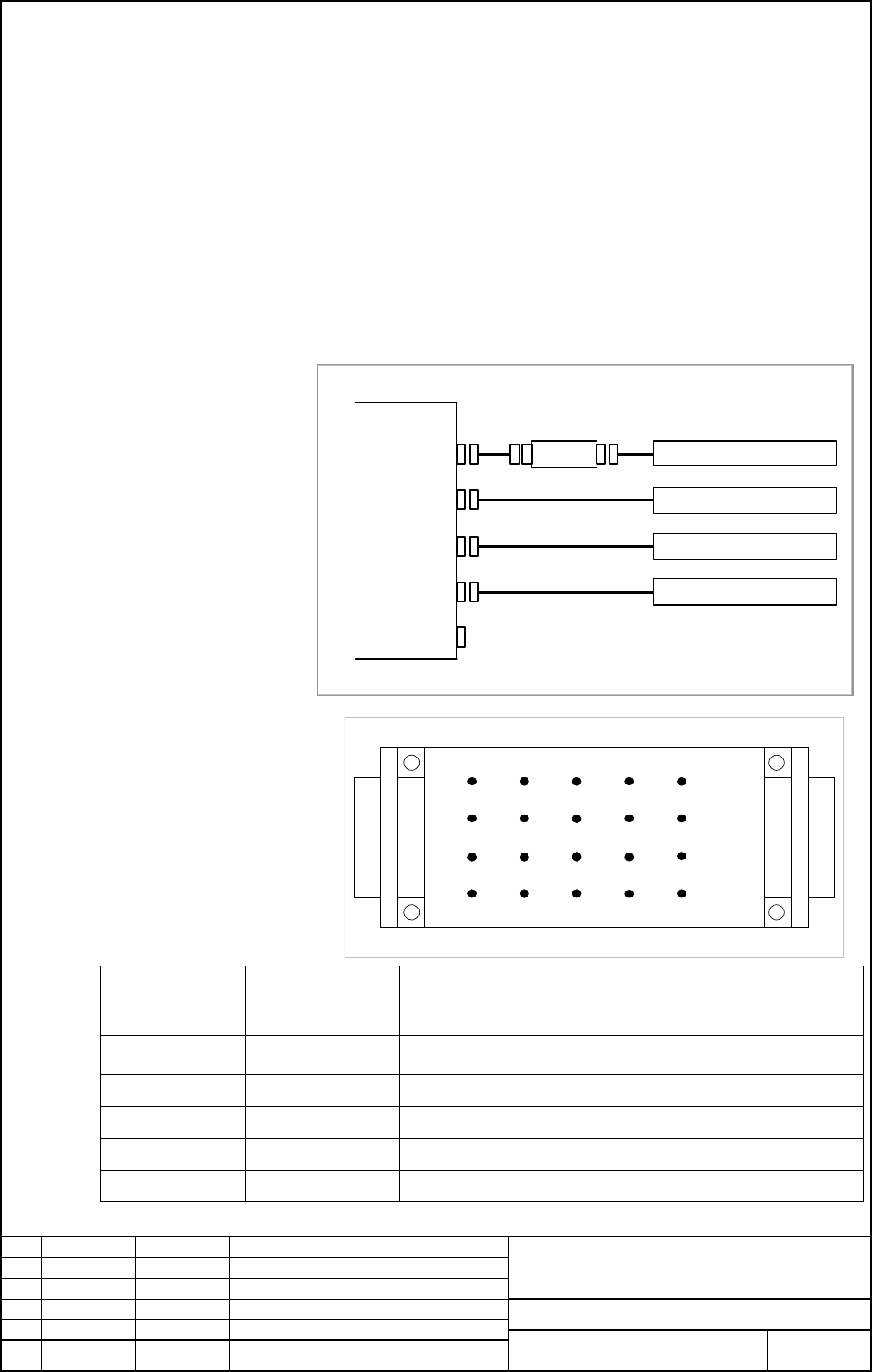
15. Check pin board
When using the check pin board, the signals, ADIF (Differential amplified signal from A
and XA input signals), BDIF (Differential amplified signal from B and XB input signals),
T0 (Reference voltage), PZ (Compared digital signal from Z and XZ input signals) can be
observed.
(1) Order specifications A06B-6071-K290
contents A20B-1005-0340 printed circuit board with check pins.
A660-2042-T031#L200R0 200mm Cable.
(2) Connection
Attach the check pin board to the cable that you want to observe the signal of the axis.
(3) Signal output
PIN number Signal name Remark
<11>
ADIF
Differentially amplified signal from A and XA input signals.
ADIF = 2 x ( XA – A )
<13> BDIF
Differentially amplified signal from B and XB input signals.
BDIF = 2 x ( XB – B )
<15> T0
2.5V DC (=1/2 Vcc)
<19> PZ
Compared digital signal from Z and XZ input signals.
<9>,<18>,<20> +5V Power source
<12>,<14>,<16> 0V Signal ground
Encoder with analog I/F(1)
Encoder with analog I/F(2)
JF111
JF112
JF113
JF114
JA4A
Encoder with analog I/F(3)
Encoder with analog I/F(4)
Check pin board
Analog input separete detector interface unit
<6>
<1> <2> <3> <4> <5>
<7> <8> <9> <10>
<11> <12> <14> <15>
<17>
<13>
<19>
CN1 CN2
<20> <18> <16>
Contents Summary of Analog Input Separate Detector Interface Unit Additional Manual
- Page 1Analog input separate detector interface unit 1. Type of applied technical documents Name Analog input separate detector interface unit Spec. No. / A-56731EN-0099 Version 2. Summary of Change New, Add, Applicable Group Name / Outline Correct, Data Delete Basic Function Optional Function Unit Mainten
- Page 23. Summary Analog input separate detector interface unit enables to directly connect encoders with analog 1Vp-p interface, having the 2048 times (Series 30i, 31i, 32i) interpolation circuit inside or the 512 times (Series 16i, 18i, 21i). Highly accurate interpolation can be achieved by the offset vo
- Page 35. Block diagram Analog input separate detector interface unit CP11A Servo amplifier module Controller unit or the previous stage servo COP10B amplifier module COP10A Linear encoder or rotary encoder with analog 1Vp-p interface Title Analog input separate detector interface unit Draw. No. A-56731E-0
- Page 46. Connection example Analog input separate detector interface unit is connected to FSSB line by optical cables. Four encoders with analog interface are available for one unit. Expansion unit of Analog input separate detector interface unit is not prepared, so, in the case that five or more encoders
- Page 51) Case of using one to four encoders with analog 1Vp-p interface CNC Servo card Servo amplifier module Optical cable COP10A COP10B COP10A COP10B COP10A Optical cable COP10B COP10A Analog input separate detector interface unit COP10B JF101 Encoder with analog I/F (1) COP10A JF102 Encoder with analog
- Page 63)Case of using one to four encoders with analog 1Vp-p interface and one to four encoders with digital interface*1) Optical cable Analog input separate detector interface unit COP10B JF111 Encoder with analog I/F (1) COP10A JF112 Encoder with analog I/F (2) DC24V CP11A JF113 Encoder with analog I/F
- Page 77. Specification Order number : A06B-6061-C201 Power supply capacity : Voltage DC24V+/-10%, Current 0.9A Method of installation : Screws or DIN rail. 8. Connection of Power supply Analog input External power supply separate detector interface unit CP11A DC24V regulated 1 +24V power supply 2 0V 3 DC2
- Page 8GND1 To the ground of the cabinet Connect the ground cable to the ground terminal at the bottom of Analog input separate detector interface unit by M3 screws as above figure. The ground cable should be connected to the ground of the cabinet. NOTE Tightening torque of the screw should be less than 0.
- Page 99. Connection with the encoder with analog 1Vp-p interface Analog input separate detector interface unit Encoder with analog interface JF111~JF114 (PCR-EV20MDT) 1 A 11 NC(ADIF) 2 XA 12 0V 3 B 13 NC(BDIF) 4 XB 14 0V 5 Z 15 NC(T0) 6 XZ 16 0V 7 17 No connection to “NC” pins 8 18 +5V 9 +5V 19 NC(PZ) 10
- Page 1010. Specification of input signal A/B(type I) Z(type I) TZ,LZ VB a/2 VXA,VXB a c/2 Usable VA Component a/2 c VOZ c/2 VOA,VOB 0V 0V A/B(type Ⅱ) Z(type Ⅱ) VB VA b/2 Vxz b d/2 Usable VXA VOZ, component b/2 d/2 VXB Vz VOXZ d VOA,VOXA 0V VOB,VOXB 0V Item Symbol Specification Unit Min. Typ. Max. typeⅠ a o
- Page 1111. Outer dimensions Title Analog input separate detector interface unit Draw. No. A-56731E-0099 01 050714 Matsukane Sheet Edit. Date Desig. Description FANUC LTD 11/18
- Page 1212. Connector locations GND1 13. Installation 1) Notes on installation (1) Install this unit in a completely enclosed cabinet. (2) Install this unit on a vertical surface, and provide a space of 100mm above and below the unit. Below the unit, do not place equipments that generate a large amount of h
- Page 13Expansion unit of Analog input Separate Separate detector detector interface unit interface unit 2) Installation using screws When using an Expansion unit of Separate detector interface unit, install the units as shown above, with the mounting holes horizontally separated by 70 to 80 mm. Title Analo
- Page 1414. Notes on installing Caution To install/remove the unit, a screwdriver has to be inserted obliquely, so sufficient access clearance are required on both sides of the units. As a guideline, if the front of an adjacent unit appears flush with the unit or slightly set back, allow a clearance of abou
- Page 15Installing the unit on the DIN rail Installing the unit on th DIN rail DIN rail Removing the unit from the DIN rail DIN rail Installing the unit 1. Hook the unit on the top of the DIN rail. 2. Push the unit in until it clicks. Removing the unit 1. Push down the lock by using a screwdriver. 2. Remove
- Page 1615. Check pin board When using the check pin board, the signals, ADIF (Differential amplified signal from A and XA input signals), BDIF (Differential amplified signal from B and XB input signals), T0 (Reference voltage), PZ (Compared digital signal from Z and XZ input signals) can be observed. (1) O
- Page 1716.Parameters setting (1) Series and editions of applicable servo software (Series 30i,31i,32i) Series 90D0/J(10) and subsequent editions Series 90E0/J(10) and subsequent editions (Series 16i,18i,21i) Swries 90B1/C(03) and subsequent editions NOTE Series 16i,18i,21i The maximum allowable speed is (P
- Page 181891 (FS15i) Number of position pulses (PPLS) 2024 (FS30i,16i) Set the number of position pulses according to the following equation: (Equation for parameter calculation) Amount of movement per motor revolution [mm] Number of position pulses = Detector signal pitch [mm]/512 If the calculation result