Series 30i-MODEL A, Improvement of stored stroke limit 1 Additional Manual Page 7
Additional Manual
A-79360E
Title
Draw
No.
Ed. Date Design Description
Date Jan.06.’04 Design. Apprv.
5/9
page
FANUC Series 30i-MODEL A
Improvement of stored stroke limit 1
Alarm 500,501:Stored stroke limit check 1
Alarm 502,503:Stored stroke limit check 2
Alarm 504,505:Stred stroke limit check 3.
Alarm 506,507:Hardware OT
Alarm 510,511:Storoke check before move
The axis which signal turns on to “1” and its direction will be registered. This axis can not
be moved the same direction still more. Only the direction which is opposite direction with
the registered direction, the axis moving can be available. The signal will be “0” by the
opposite direction moving.
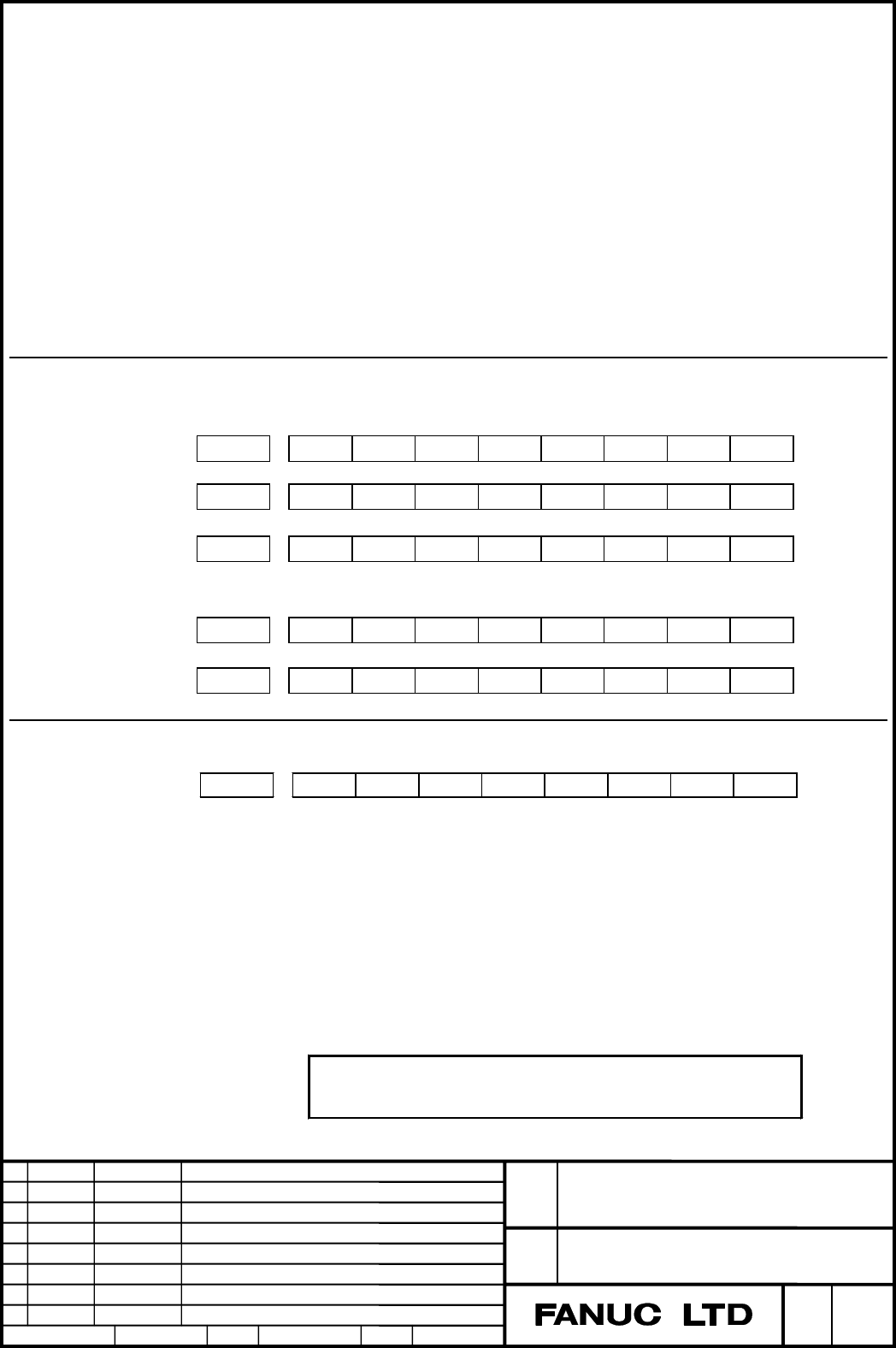
Signal address
#7 #6 #5 #4 #3 #2 #1 #0
Gn007 RLSOT EXLM
Gn104 +EXL8 +EXL7 +EXL6 +EXL5 +EXL4 +EXL3 +EXL2 +EXL1
Gn105 -EXL8 -EXL7 -EXL6 -EXL5 -EXL4 -EXL3 -EXL2 -EXL1
#7 #6 #5 #4 #3 #2 #1 #0
Fn124 +OT8 +OT7 +OT6 +OT5 +OT4 +OT3 +OT2 +OT1
Fn126 -OT8 -OT7 -OT6 -OT5 -OT4 -OT3 -OT2 -OT1
Parameter
#7 #6 #5 #4 #3 #2 #1 #0
1300 BFA LMS NAL
[Input type] Setting input
[Data type] Bit path
# 1 NAL Specifies whether to issue an alarm related to stored stroke check 1, as
follows:
0: To issue an alarm.
1: Not to issue an alarm; the stroke limit reached signal F124 or F126 is
output (for a manual operation).
NOTE
When this parameter is set to “1”, if the axis enters to the stored
stroke limit 1 in auto operatin
g
mode, the alarm has been issued.
Contents Summary of Series 30i-MODEL A, Improvement of stored stroke limit 1 Additional Manual
- Page 1TECHNICAL REPORT NO. TMN 04/020E Date :Mar .30, 2004 General Manager of Software Laboratory FANUC Series 30i-A Newly additional functions 1. Communicate this report to: Your information only GE Fanuc-N, GE Fanuc-E FANUC Robotics MILACRON Machine tool builder Sales agency End user 2. Summary for Sale
- Page 2FANUC Series30i –A newly additional functions Drawing number Functions 1 A-79227E External Data Input 2 A-79226E One Touch Macro call 3 A-79196E Temporary absolute coordinate setting 4 A-79354E System alarm 5 A-79349E Touch Panel Control 6 A-79253E Distance coded linear scale interface 7 A-79364E Li
- Page 3FANUC Series 30i-MODEL A Improvement of stored stroke limit 1 Specifications FANUC Series 30i-MODEL A Title Improvement of stored stroke limit 1 Draw A-79360E No. Ed. Date Design Description page 1/9 Date Jan.06.’04 Design. Apprv.
- Page 4In the “2.3.2 Stored Stroke Check 1” of the CONNECTION MANUAL (B-63943EN-1), the following description of the specification has been added. 1.The following descriptions have been added in the “explanation”. In this time, the “Stroke limit reached signals” can be output by the setting of the paramete
- Page 52.3.2 Stored Stroke Check 1 Overview A machine movable range is set with coordinates in the machine coordinate system in parameters. If the machine attempts to move beyond the range, it is decelerated and stopped and an alarm is displayed. This function is enabled after manual reference position ret
- Page 6Stroke check release signal RLSOT
- Page 7Alarm 500,501:Stored stroke limit check 1 Alarm 502,503:Stored stroke limit check 2 Alarm 504,505:Stred stroke limit check 3. Alarm 506,507:Hardware OT Alarm 510,511:Storoke check before move The axis which signal turns on to “1” and its direction will be registered. This axis can not be moved the s
- Page 8#2 LMS The EXLM signal for switching stored stroke check 0: Disabled 1: Enabled When bit 0 (DLM) of parameter No. 1301 is set to 1, the stored stroke check 1 switch signal EXLM (G007#6) is made invalid. #7 BFA When the stored stroke check 1, 2, or 3 alarm is issued, an function (T series), or a chuc
- Page 91320 Positive (+) direction coordinate of stored stroke limit 1 of each axis I 1321 Negative (-) direction coordinate of stored stroke limit 1 of each axis I [Input type] Parameter input [Data type] Real axis [Unit of data] mm, inch, degree (machine unit) [Minimum unit of data]Depend on the incremen
- Page 101326 Coordinate II along each axis in the plus direction of stored stroke limit 1. 1327 Coordinate II along each axis in the minus direction of stored stroke limit 1 [Input type] Parameter input [Data type] Realaxis [Unit of data] mm, inch, degree (machine unit) [Minimum unit of data]Depend on the i
- Page 11Caution CAUTION 1. If the two points for specifying a forbidden area are identical, all areas are handled as forbidden areas for stored stroke check 2. The size of a forbidden area must be set carefully. If the size is set incorrectly, the stroke becomes infinite. Note NOTE 1. Specify diameter value