Series 0i - Model A Connection manual (Hardware) Page 28
Connection manual (Hardware)
B–63503EN/02
3. INSTALLATION
16
System ground
SERVO1
JS1A
A–OUT
JA 8A
IOL INK
JD 1A
CPS
4
MAIN
STATUS
ALARM
BATTERY
231
MEMORY
CARD
CNMC
RSW1
I/O
PSU
MPG
JA3B
FUSE75A
PIL
CP1A
DCIN
24V
5A
CP1B
DCOUT
24V
1A
R
L
SPDL–1
JA 7A
SERVO2
JS2A
SERVO3
JS3A
CRT
JA1
MDI
JA2
R232–1
JD5A
R232–2
JD5B
SCALE1
JF21
SCALE2
JF22
SCALE3
JF23
SC–ABS
JF25
MINI
SLOT
FA-
NUC
FANUC
R
L
FANUC
Control unit
M3 terminal for
signal ground (SG)
Ground plate
M3
Ground cable
Frame
ground
(FG)
= Ground plate of
the cabinet
Ground cable
(upper 2mm
2
)
SERVO4
JS4A
SCALE4
JF24
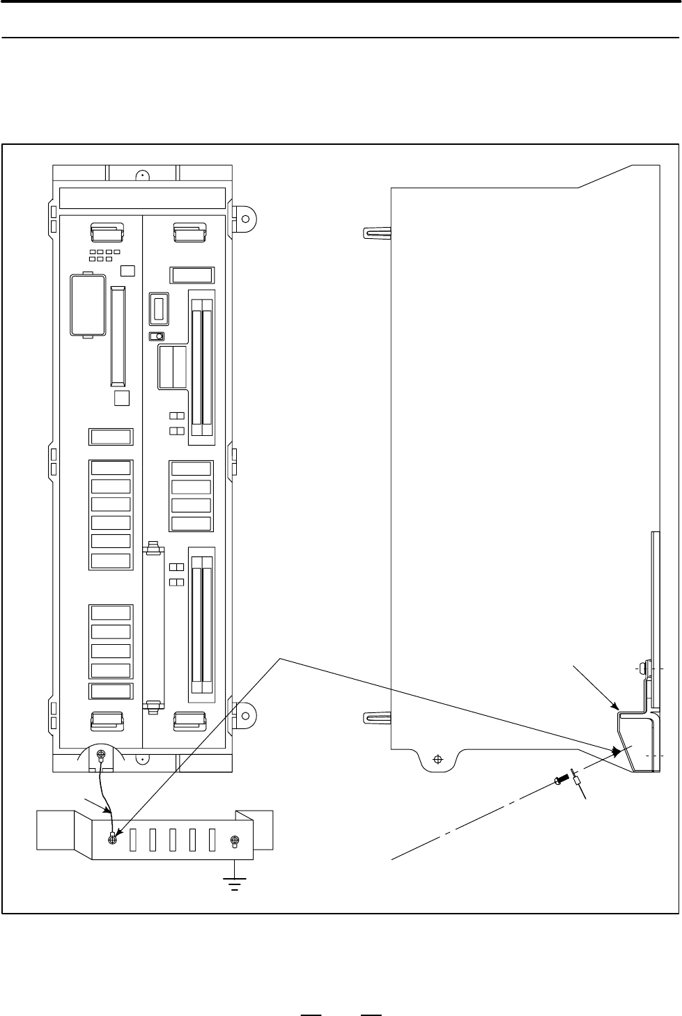
Connect the 0 V line of the electronic circuit in the control unit with the
ground plate of the cabinet via the signal ground (SG) terminal.
The SG terminal is located below the main board of the control unit.
3.5.3
Connecting the Signal
Ground (SG) of the
Control Unit
Contents Summary of Series 0i - Model A Connection manual (Hardware)
- Page 1CONNECTION MANUAL (HARDWARE) B-63503EN/02�
- Page 2Ȧ No part of this manual may be reproduced in any form. Ȧ All specifications and designs are subject to change without notice. In this manual we have tried as much as possible to describe all the various matters. However, we cannot describe all the matters which must not be done, or which cannot be
- Page 3B–63503EN/02 DEFINITION OF WARNING, CAUTION, AND NOTE DEFINITION OF WARNING, CAUTION, AND NOTE This manual includes safety precautions for protecting the user and preventing damage to the machine. Precautions are classified into Warning and Caution according to their bearing on safety. Also, supplem
- Page 4
- Page 5B–63503EN/02 PREFACE PREFACE This manual describes the electrical and structural specifications required for connecting the FANUC Series 0i CNC control unit to a machine tool. The manual outlines the components commonly used for FANUC CNC control units, as shown in the configuration diagram in Chapt
- Page 6PREFACE B–63503EN/02 Configuration of the This manual consists of Chapters 1 to 15 and Appendixes. manual Chapter title Description Chapter 1 Outlines connections for the Series 0i and guides the reader concerning addi- CONFIGURATION tional details. Chapter 2 This chapter shows the total connection
- Page 7B–63503EN/02 PREFACE Related manuals The table below lists manuals related to the Series 0i. In the table, this manual is marked with an asterisk (*). Manuals Related to the Series 0i Specification Manual name number DESCRIPTIONS B–62502EN CONNECTION MANUAL (Hardware) B–62503EN * CONNECTION MANUAL (
- Page 8
- Page 9B–63503EN/02 Table of Contents DEFINITION OF WARNING, CAUTION, AND NOTE . . . . . . . . . . . . . . . . . . . . . . . . . . s–1 PREFACE . . . . . . . . . . . . . . . . . . . . . . . . . . . . . . . . . . . . . . . . . . . . . . . . . . . . . . . . . . . . . . . . p–1 1. CONFIGURATION . . . . . . . .
- Page 10Table of Contents B–63503EN/02 5.1.4 Various LCD Units Interface . . . . . . . . . . . . . . . . . . . . . . . . . . . . . . . . . . . . . . . . . . . . . . . . . . . . . . . . . 47 5.1.5 Adjusting the 8.4″ Color LCD . . . . . . . . . . . . . . . . . . . . . . . . . . . . . . . . . . . . . . . . . .
- Page 11B–63503EN/02 Table of Contents 9.4.3 Connections . . . . . . . . . . . . . . . . . . . . . . . . . . . . . . . . . . . . . . . . . . . . . . . . . . . . . . . . . . . . . . . . . . . . . 116 9.4.3.1 Pin assignment . . . . . . . . . . . . . . . . . . . . . . . . . . . . . . . . . . . . . . . . . . .
- Page 12Table of Contents B–63503EN/02 10.EMERGENCY STOP SIGNAL . . . . . . . . . . . . . . . . . . . . . . . . . . . . . . . . . . . . . . . . . . . 172 11.HIGH–SPEED SERIAL BUS (HSSB) . . . . . . . . . . . . . . . . . . . . . . . . . . . . . . . . . . . . . 174 11.1 OVERVIEW . . . . . . . . . . . . . . .
- Page 13B–63503EN/02 1. CONFIGURATION 1 CONFIGURATION 1
- Page 141. CONFIGURATION B–63503EN/02 1.1 The following figure shows the configuration of FANUC Series 0i control unit. NAME OF EACH PART This manual describes how to connect the units illustrated in this diagram. OF CONTROL UNIT The numbers in parentheses shown in the diagram are section references for thi
- Page 15B–63503EN/02 1. CONFIGURATION 1.2 GENERAL OF HARDWARE Main board I/O board S Main CPU S Power PCB (built–in) S Memory DC–DC converter System software, S DI/DO Macro program, S Reader/puncher I/F Ladder program, S MDI control Parameter, and etc. S Display control S PMC control S Manual pulse generato
- Page 162. TOTAL CONNECTION DIAGRAM B–63503EN/02 2 TOTAL CONNECTION DIAGRAM Power C Main board supply o 24VDC n t Units that can be r connected with the o I/O Link l u n i t Position coder Analog spindle Analog amplifier spindle Position coder Serial spindle amplifier Serial spindle Servo amplifier L–axis s
- Page 17B–63503EN/02 2. TOTAL CONNECTION DIAGRAM I/O Board D C I/O Board o n Power supply t 24VDC r Power supply unit o Display unit DC–IN (CP1A) l DC–OUT(CP1B) (CN2)DC–IN u (CN1)CRT n CRT(JA1) (JA1)LCD i t MDI unit MDI(JA2) (CK1)MDI R232C–1(JD5A) RS–232–C I/O device (channel 1) R232C–2(JD5B) RS–232–C I/O d
- Page 183. INSTALLATION B–63503EN/02 3 INSTALLATION 6
- Page 19B–63503EN/02 3. INSTALLATION 3.1 ENVIRONMENT FOR INSTALLATION 3.1.1 The peripheral units, such as the control unit and CRT/MDI, have been Environmental designed on the assumption that they are housed in closed cabinets. In this manual “cabinet” refers to the following: Requirements Outside (1) Cabin
- Page 203. INSTALLATION B–63503EN/02 3.2 POWER SUPPLY 3.2.1 The following units related to the CNC control unit require input power Power Supply for CNC of 24 VDC ±10%. Control Units Table 3.2.1 Power supply Power supply Unit Power supply voltage 0i control unit 24 VDC ±10% 3.5A (only control unit) ± ±10% i
- Page 21B–63503EN/02 3. INSTALLATION 3.3 When a cabinet is designed, it must satisfy the environmental conditions described in Sec. 3.1. In addition, the magnetic interference on the CRT DESIGN AND screen, noise resistance, and maintenance requirements must be INSTALLATION considered. The cabinet design mus
- Page 223. INSTALLATION B–63503EN/02 (9) The CRT screen can be distorted by magnetic interference. Arranging magnetic sources must be done with care. If magnetic sources (such as transformers, fan motors, electromagnetic contactors, solenoids, and relays) are located near the CRT display, they frequently di
- Page 23B–63503EN/02 3. INSTALLATION 3.4 The purpose of the thermal design of the cabinet is to limit the difference in temperature between the air in the cabinet and the outside air to 10°C THERMAL DESIGN OF or less when the temperature in the cabinet increases. THE CABINET The internal air temperature of
- Page 243. INSTALLATION B–63503EN/02 3.4.3 Heat Loss of Each Unit Name Heat loss Control unit Series 0i 60W Display unit 9″CRT unit 14W 8.4″LCD color unit 20W 7.2″LCD unit 10W 10.4″LCD unit 20W Multi–tap transformer for control unit 51W Heat from the MDI unit is negligible. 12
- Page 25B–63503EN/02 3. INSTALLATION 3.5 The CNC has been steadily reduced in size using surface–mount and custom LSI technologies for electronic components. The CNC also is ACTION AGAINST designed to be protected from external noise. However, it is difficult to NOISE measure the level and frequency of nois
- Page 263. INSTALLATION B–63503EN/02 Group Signal line Action Cable between the CNC and servo Bind the cables in group C sepa- amplifier rately from group A, or cover group C with an electromagnet- Cable for position and velocity ic shield. feedback Separate group C as far from Group B as possible. Cable be
- Page 27B–63503EN/02 3. INSTALLATION 3.5.2 The following ground systems are provided for the CNC machine tool: Ground (1) Signal ground system (SG) The signal ground (SG) supplies the reference voltage (0 V) of the electrical signal system. (2) Frame ground system (FG) The frame ground system (FG) is used f
- Page 283. INSTALLATION B–63503EN/02 3.5.3 Connecting the Signal Ground (SG) of the Control Unit Control unit MAIN I/O PSU 1 2 3 4 STATUS ALARM CPS MPG JA3B FUSE75A PIL BATTERY MEMORY CARD CNMC CP1A CP1B DCIN DCOUT 24V 24V 5A 1A RSW1 R IOL INK L JD 1A SPDL–1 CRT JA 7A JA1 A–OUT MDI JA 8A JA2 SERVO1 R232–1 J
- Page 29B–63503EN/02 3. INSTALLATION MDI CRT Approx. 15mm M4 stud Approx. 20 mm (for 9″ CRT/MDI unit) 9″ CRT/MDI unit Approx. 150 mm (for 8.4″ LCD/MDI unit) 8.4″ LCD/MDI unit MDI LCD M4 stud Approx. 17mm Approx. 151mm 7.2″ LCD/MDI unit LCD M4 stud Approx. 20mm 10.4″ LCD unit Approx. 50mm 17
- Page 303. INSTALLATION B–63503EN/02 Approx. 17mm M3 screw hole Approx. 60mm 8.4″ LCD unit M4 stud Approx. 17mm Stand–alone type MDI unit (small) Approx. 32mm M4 stud Approx. 30mm Stand–alone type MDI unit (Full–key for 10.4″ LCD) Approx. 25mm 18
- Page 31B–63503EN/02 3. INSTALLATION 3.5.4 The AC/DC solenoid and relay are used in the power magnetics cabinet. Noise Suppressor A high pulse voltage is caused by coil inductance when these devices are turned on or off. This pulse voltage induced through the cable causes the electronic circuits to be distu
- Page 323. INSTALLATION B–63503EN/02 3.5.5 The CNC cables that require shielding should be clamped by the method Cable Clamp and shown below. This cable clamp treatment is for both cable support and proper grounding of the shield. To insure stable CNC system operation, Shield Processing follow this cable cl
- Page 33B–63503EN/02 3. INSTALLATION ÇÇ Machine side installation ÇÇ board ÇÇ Control unit ÇÇ ÇÇ ÇÇ ÇÇ ÇÇ ÇÇ ÇÇ ÇÇ Ground plate ÇÇ ÇÇ ÇÇ Metal fittings ÇÇ ÇÇ for clamp ÇÇ Shield cover Fig.3.5.5(b) Cable clamp (2) Prepare ground plate like the following figure. Ground terminal (grounded) Hole for securing me
- Page 343. INSTALLATION B–63503EN/02 Ground 8mm plate 12mm 20mm Fig.3.5.5(d) Ground plate holes (Reference) Outer drawings of metal fittings for clamp. Max. 55mm 28mm 6mm 17mm Fig.3.5.5(e) Outer drawings of metal fittings for clamp Ordering specification for metal fittings for clamp A02B–0124–K001 (8 pieces
- Page 35B–63503EN/02 3. INSTALLATION 3.6 CONTROL UNIT 3.6.1 The rack consists of a plastic box, fan motors and a backplane PCB. The Installation of the air comes into the rack from the bottom and goes out through the fan motor, which is located on the top of the rack. Space as shown in Fig. Control Unit 3.6
- Page 363. INSTALLATION B–63503EN/02 3.7 Fig. 3.7 (a) shows the grid of connector location. Control board may not have all connectors as shown in Fig. 3.7 (a). CABLE LEAD–IN For actual connector layout of each board, please see the connector layout DIAGRAM diagrams in Fig. 3.8 (a) or later. 8 36 74 129 173
- Page 37B–63503EN/02 3. INSTALLATION Memory card (80) 172 Unit : mm Fig.3.7 (b) 25
- Page 383. INSTALLATION B–63503EN/02 3.8 CONNECTOR LAYOUT DIAGRAM LED display Connector name and comment Function Upper Lower LED STATUS/ALARM Battery for memory CPB Battery BATTERY Memory card MEMORY/CARD CNMC Rotary switch RSW1 for maintenance Serial I/O Link IOLINK JD1A Serial spindle SPDL–1 JA7A Analog
- Page 39B–63503EN/02 3. INSTALLATION Connector name and comment Function Upper Lower Position 1 Serial port R232–1 JD5A 2 Fuse FUSE 3 4 Pilot lamp PIL 5 24VDC output (R side) DC OUT CP1B 6 24VDC input (L side) DC IN CP1A 7 R Operator’s panel I/O (R side) DI/DO–1 CB104 8 L Machine side I/O (L side) DI/DO–2 C
- Page 403. INSTALLATION B–63503EN/02 Function Comment Mode switch SW LED display ST– 4 3 2 1 AL– 1 2 High–speed serial COP7 bus interface Fig.3.8 (c) High–speed serial bus interface board 28
- Page 41B–63503EN/02 4. POWER SUPPLY CONNECTION 4 POWER SUPPLY CONNECTION 29
- Page 424. POWER SUPPLY CONNECTION B–63503EN/02 4.1 This section explains the connection of power supply for Series 0i control unit. GENERAL 30
- Page 43B–63503EN/02 4. POWER SUPPLY CONNECTION 4.2 TURNING ON AND OFF THE POWER TO THE CONTROL UNIT 4.2.1 Supply power (24VDC) to the control uint of Series 0i from an external Power Supply for the sources. Control Unit Provide ON/OFF circuit A for turning the AC power on and off or ON/OFF circuit B for tu
- Page 444. POWER SUPPLY CONNECTION B–63503EN/02 ON/OFF circuit (example) For example, “ON/OFF circuit” is as follows : (Fig. 4.2.1 (b) ) Select the circuit devices, in consideration of its capacity. +24V +24V ry1 OUTPUT 24 VDC RY1 The power rating is the DC INPUT sum of power requirements 24 V on the load s
- Page 45B–63503EN/02 4. POWER SUPPLY CONNECTION 4.2.2 Specifications of recommended external 24 VDC power supply +24V Input Power (regulated power supply): (The power supply must satisfy UL1950.) Specifications Output voltage: +24 V (10% (21.6 V to 26.4 V) (including ripple voltage and noise. See the figure
- Page 464. POWER SUPPLY CONNECTION B–63503EN/02 S Notes to take when the When the vertical axis exists, select the DC power supply that has a long voltage vertical axis exists hold time to decrease the amount of vertical axis falling during power–off (including a power failure). If the operating voltage dro
- Page 47B–63503EN/02 4. POWER SUPPLY CONNECTION Example 2 Regulated AC input power CNC unit supply Device with large rush current For a circuit configuration in 2, connect another regulated power supply to be specifically used for the device with remarkable load fluctuations so that the CNC and other units
- Page 484. POWER SUPPLY CONNECTION B–63503EN/02 The following circuit configuration is recommended. The power to the CNC and other units (A unit with I/O Link, FANUC Servo Unit (Series with an I/O link (β amplifier with an I/O link), and so on in the sample configuration below)) is assumed to be turned on a
- Page 49B–63503EN/02 4. POWER SUPPLY CONNECTION 4.2.3 Turn on the power to each unit in the following order or all at the same Procedure for Turning time. On the Power 1. Power to the overall machine (200 VAC) 2. Servo amplifier control power supply (200 VAC) 3. Power to the slave I/O units connected via th
- Page 504. POWER SUPPLY CONNECTION B–63503EN/02 4.2.4 Turn off the power to each unit in the following order or all at the same Procedure for Turning time. Off the Power 1. Power to the slave I/O units connected via the I/O link, power to the display unit (24VDC), and power to the CNC control unit (24 VDC),
- Page 51B–63503EN/02 4. POWER SUPPLY CONNECTION 4.3 Supply power to the control unit from external resouce. CABLE FOR Series 0i control unit External power POWER SUPPLY TO CONTROL UNIT CP1A 1 +24V 24VDC stabilized 2 0V power 3 24VDC "10% Cable CP1A AMP Japan 1–178288–3 (housing) 1–175218–5 (Contact) Externa
- Page 524. POWER SUPPLY CONNECTION B–63503EN/02 4.4 BATTERY 4.4.1 Part programs, offset data, and system parameters are stored in CMOS Battery for Memory memory in the control unit. The power to the CMOS memory is backed up by a lithium battery mounted on the front panel of the control unit. The Backup (3VD
- Page 53B–63503EN/02 4. POWER SUPPLY CONNECTION Front panel of control MAIN unit main board 1 2 3 4 STATUS ALARM CP8 Battery connector Battery case BATTERY MEMORY CARD CNMC Battery (Ordering drawing RSW1 number A02B–0177–K106) Fig.4.4.1(a) Replacing the battery(1) 4 Remove the connector from the battery. Fr
- Page 544. POWER SUPPLY CONNECTION B–63503EN/02 4.4.2 One battery unit can maintain current position data for six absolute pulse Battery for Separate coders for a year. When the voltage of the battery becomes low, APC alarms 3n6 to 3n8 (n: Absolute Pulse Coders axis number) are displayed on the CRT display.
- Page 55B–63503EN/02 5. CONNECTION TO CNC PERIPHERALS 5 CONNECTION TO CNC PERIPHERALS 43
- Page 565. CONNECTION TO CNC PERIPHERALS B–63503EN/02 5.1 CONNECTION TO THE DISPLAY UNIT 5.1.1 The display unit is used for displaying the programs, parameters etc, and Outline supporting the machine operation. The Series 0i supports the following display units: D 9″ monochrome CRT unit D 7.2″ monochrome LC
- Page 57B–63503EN/02 5. CONNECTION TO CNC PERIPHERALS 5.1.2 Connection to Display Unit Connection to Series 0i Control unit CP1B DC OUT Power supply cable CRT JA1 Video cable CN2 (CRT) CN1 (CTR) CP5 (LCD) JA1 (LCD) CRT/MDI, LCD/MDI unit 45
- Page 585. CONNECTION TO CNC PERIPHERALS B–63503EN/02 5.1.3 9″ CRT Display Unit Interface Series 0i CRT unit JA1 CN1 (PCR–EV20MDT) (MR–20RM) 01 VDR 11 1 VDR 14 8 0V 02 0V 12 VSYNC 2 HSYNC 15 9 0V 03 VDG 13 3 VSYNC 16 10 0V 04 0V 14 0V 4 VDG 17 (0V) 11 0V 05 VDB 15 5 VDB 18 (0V) 12 0V 06 0V 16 0V 6 19 13 07
- Page 59B–63503EN/02 5. CONNECTION TO CNC PERIPHERALS 5.1.4 Various LCD Units Interface Series 0i LCD unit JA1 JA1 (PCR–HV20MDT) (PCR–HV20MDT) 01 VDR 11 01 VDR 11 02 0V 12 VSYNC 02 0V 12 VSYNC 03 VDG 13 03 VDG 13 04 0V 14 0V 04 0V 14 0V 05 VDB 15 05 VDB 15 06 0V 16 0V 06 0V 16 0V 07 17 07 17 08 18 HSYNC 08
- Page 605. CONNECTION TO CNC PERIPHERALS B–63503EN/02 5.1.5 (1) Applied unit Adjusting the 8.4″ Name Specification number Color LCD 8.4″ color LCD/MDI unit A02B–0279–C081#TA, #TAS A02B–0279–C081#MA, #MAS 8.4″ color LCD unit A02B–0279–C050 (2) Adjustment point (as viewed from the rear of the display unit TM1
- Page 61B–63503EN/02 5. CONNECTION TO CNC PERIPHERALS 5.1.6 (1) Applied unit Adjusting the 7.2″ Name Specification number Monochrome LCD 7.2″ STN monochrome LCD/MDI unit A02B–0279–C071#MA, MAS, TA, TAS (2) Adjustment point (as viewed from the rear of the display unit) VRP1 SW1 (3) Adjustment method (a) Disp
- Page 625. CONNECTION TO CNC PERIPHERALS B–63503EN/02 5.1.7 (1) Applied unit Adjusting the 10.4″ Name Specification number Color LCD 10.4″ TFT color LCD unit A02B–0279–C060 (2) Tuning locations Color Liquid Crystal Display(Rear Part) TM1 SW1 (3) Adjustment method (a) Tuning flicker (TM1) If the display flic
- Page 63B–63503EN/02 5. CONNECTION TO CNC PERIPHERALS 5.2 CONNECTION OF MDI UNIT 5.2.1 Manual data input devices for the Series 0i are called MDI units. MDI units are keyboards used to enter data such as CNC programs and General parameters into the CNC. 5.2.2 Connection to the MDI Unit Control unit MDI JA2
- Page 645. CONNECTION TO CNC PERIPHERALS B–63503EN/02 5.2.3 Connection to the Standard MDI Unit Series 0i control unit MDI unit JA2 CK1 01 :KEY00 11 :KEY01 01 :KEY00 11 :KEY01 02 :KEY02 12 :KEY03 02 :KEY02 12 :KEY03 03 :KEY04 13 :KEY05 03 :KEY04 13 :KEY05 04 :KEY06 14 :KEY07 04 :KEY06 14 :KEY07 05 :COM00 15
- Page 65B–63503EN/02 5. CONNECTION TO CNC PERIPHERALS 5.2.4 Varied MDI Key Switch D 9″CRT/MDI unit (T series) D 7.2″LCD/MDI unit (T series) D 8.4″LCD/MDI unit (T series) D Stand–alone type small MDI unit (T series) English display Symbol display 53
- Page 665. CONNECTION TO CNC PERIPHERALS B–63503EN/02 D 9″CRT/MDI unit (M series) D 7.2″LCD/MDI unit (M series) D 8.4″LCD/MDI unit (M series) D Stand–alone type small MDI unit (M series) English display Symbol display 54
- Page 67B–63503EN/02 5. CONNECTION TO CNC PERIPHERALS D Stand–alone type full–key MDI unit (T series) English display Symbol display 55
- Page 685. CONNECTION TO CNC PERIPHERALS B–63503EN/02 D Stand–alone type full–key MDI unit (M series) English display Symbol display 56
- Page 69B–63503EN/02 5. CONNECTION TO CNC PERIPHERALS 5.3 CONNECTING I/O DEVICES 5.3.1 I/O devices are used for inputting various data such as CNC programs and General parameters from external devices to the CNC or outputting data from the CNC to external devices. The Handy File is one of the I/O devices fo
- Page 705. CONNECTION TO CNC PERIPHERALS B–63503EN/02 5.3.2 Connecting I/O Devices Control unit Punch panel R232–1 JD5A R232–2 JD5B Handy File 58
- Page 71B–63503EN/02 5. CONNECTION TO CNC PERIPHERALS 5.3.3 RS–232–C Serial Port CNC RELAYING CONNECTOR JD5A, JD5B (DBM–25S) (PCR–EV20MDT) 1 FG 14 1 RD 11 SD 2 SD 15 2 0V 12 0V 3 RD 16 3 DR 13 ER 4 RS 17 4 0V 14 0V 5 CS 18 5 CS 15 RS 6 DR 19 6 0V 16 0V 7 SG 20 ER 7 CD 17 8 CD 21 8 0V 18 9 22 9 19 +24V 10 23
- Page 725. CONNECTION TO CNC PERIPHERALS B–63503EN/02 5.3.4 RS–232–C Interface Specification RS–232–C Interface Generally signals as follows are used in RS–232–C interface. signals CNC Output SD (Send data) Input RD (Recieve data) RS (Request to Send) When CS is not used short CS and RS. CS (Enable to send)
- Page 73B–63503EN/02 5. CONNECTION TO CNC PERIPHERALS Signal description of RS–232–C Signal RS–232–C interface name circuit I/O Description number SD 103 Out- Sending Start bit Stop bit put data RD 104 Input Receiv- ON 1 2 3 4 5 6 7 8 OFF ing (When ISO code “0” is sent) data RS 105 Input Sending This signal
- Page 745. CONNECTION TO CNC PERIPHERALS B–63503EN/02 Transmission Method of RS–232–C interface Start–stop Generally, two transmission methods are available at the serial interface. Series 0i use the start–stop method. With this method, start and stop signals are output before and after each data bit. One c
- Page 75B–63503EN/02 5. CONNECTION TO CNC PERIPHERALS Table 5.3.4(a) ISO code EIA code Meaning Character 8 7 6 5 4 3 2 1 Character 8 7 6 5 4 3 2 1 0 f f F 0 f F Numeral 0 1 f f f F f 1 F f Numeral 1 2 f f f F f 2 F f Numeral 2 3 f f F f f 3 f F f f Numeral 3 4 f f f F f 4 F f Numeral 4 5 f f F f f 5 f F f f
- Page 765. CONNECTION TO CNC PERIPHERALS B–63503EN/02 NOTE 1 When the external device is equipped with an ISO/EIA converter, the following items must be noted in Table 5.3.4(a). Control out (Comment field start) Control in (Comment field end) EIA code (.......................) CR o .................... Cond
- Page 77B–63503EN/02 5. CONNECTION TO CNC PERIPHERALS (iv) Cable length The cable length depends on the external device type. Consult with the device manufacturers for actual connecting cable lengths. When cable A (A66L–0001–0041) is used, cable length is as follows by the specification of NC. for RS–232–C
- Page 785. CONNECTION TO CNC PERIPHERALS B–63503EN/02 Time chart when the NC (1) NC output DC2. send data (Punch out) (2) NC outputs punch data in succession. (3) When data processing is delayed at the external device. (a) Data output stops within two characters including a currently transmitting character
- Page 79B–63503EN/02 5. CONNECTION TO CNC PERIPHERALS Connection between RS–232–C interface and I/O devices CNC I/O device side SD SD RD RD RS RS CS CS ER ER DR DR CD CD SG SG FG FG 67
- Page 805. CONNECTION TO CNC PERIPHERALS B–63503EN/02 5.3.5 FANUC Handy File Connection Cable side connector Connector: DBM–25P (Japan Aviation Elec- tronic Inc., Ltd.) CNC Cover: DB–C2–J9 (Japan Aviation Electronic Inc., Ltd.) JD5A, JD5B (PCR–EV20MDT) Relaying 1 RD 11 SD cable FANUC 2 0V 12 0V Handy File 3
- Page 81B–63503EN/02 5. CONNECTION TO CNC PERIPHERALS 5.4 CONNECTING THE MANUAL PULSE GENERATOR 5.4.1 Manual pulse generators are used to manually move an axis in the handle General feed mode. Up to two manual pulse generators can be connected with the 0i–TA. Up to three manual pulse generators can be conne
- Page 825. CONNECTION TO CNC PERIPHERALS B–63503EN/02 5.4.2 Connection to Manual Pulse Generators CNC Manual Pulse Generator I/O PCB Manual Pulse Generator unit #1 JA3B (PCR–EV20MDT) (M3 screw terminal) 1 HA1 11 0V 3 4 5 6 2 HB1 12 0V +5V 0V HA1 HB1 3 HA2 13 0V Manual Pulse Generator unit #2 4 HB2 14 0V (M3
- Page 83B–63503EN/02 5. CONNECTION TO CNC PERIPHERALS 5.4.3 Manual pulse generators are supplied with 5 VDC power the same as Cable Length When pulse coders. The drop in voltage due to cable resistance must not exceed 0.2V (on 0V and 5V lines in total). Only One Manual Pulse Generator is Used 0.2y 0.1 R 2L
- Page 846. SPINDLE CONNECTION B–63503EN/02 6 SPINDLE CONNECTION The following two configurations of the spindle interface are available in Series 0i. Serial spindle P/C Serial Spindle SPDL–1(JA7A) JA7B spindle Motor JA7A amplifier Main board Analog spindle Position coder return signal (A/B/Z phase) SPDL–1(J
- Page 85B–63503EN/02 6. SPINDLE CONNECTION 6.1 SERIAL SPINDLE INTERFACE CNC Spindle amplifier module JA7A (Main board) JA7B (PCR–EV20MDT) (PCR–E20MDT) 1 SIN 11 0V 1 SIN 11 0V 2 :SIN 12 0V 2 :SIN 12 0V 3 SOUT 13 0V 3 SOUT 13 0V 4 :SOUT 14 0V 4 :SOUT 14 0V 5 15 0V 5 15 0V 6 16 0V 6 16 0V 7 17 7 17 8 18 8 18 9
- Page 866. SPINDLE CONNECTION B–63503EN/02 6.2 ANALOG SPINDLE INTERFACE CNC JA8A (Main board) Signal name Description (PCR–EV20MDT) SVC, ES Spindle command voltage and common line 1 0V 11 0V 2 CLKX0 12 CLKX1 ENB1, ENB2 Spindle enable signal 3 0V 13 0V (Note 1) 4 FSX0 14 FSX1 CLKX0, CLKX1, Feed axis check si
- Page 87B–63503EN/02 6. SPINDLE CONNECTION 6.3 POSITION CODER CNC INTERFACE JA7A(Main board) Name Description (PCR–EV20MDT) SC, :SC Position coder C–phase signal 1 SC 11 2 :SC 12 0V PA, :PA Positon coder A–phase signal 3 SOUT 13 4 :SOUT 14 0V PB, :PB Position coder B–phase signal 5 PA 15 6 :PA 16 0V SOUT, S
- Page 887. SERVO INTERFACE B–63503EN/02 7 SERVO INTERFACE 76
- Page 89B–63503EN/02 7. SERVO INTERFACE 7.1 This chapter describes how to connect the servo unit to the Series 0i. OUTLINE For connection on control motor amplifier α series or β series, refer to the Descriptions manual. 7.1.1 Interface to the Servo Amplifier Series 0i Servo Amplifier Module JSnA JSnB (PCR–
- Page 907. SERVO INTERFACE B–63503EN/02 NOTE 1 The total length of the cable between the CNC and amplifier and that between the amplifier and motor shall not exceed 50m. 2 As the current feedback lines (IRn and ISn), use the middle twisted pair of the recommended cable. If any other pair is used, abnormal n
- Page 91B–63503EN/02 7. SERVO INTERFACE 7.1.2 Separate Type Detector Interface Control unit Linear scale SCALE1 JF21 SCALE2 JF22 SCALE3 JF23 SCALE4 JF24 79
- Page 927. SERVO INTERFACE B–63503EN/02 7.1.3 Connection of Battery for Separate Type Absolute Detector Control unit + Battery case for separate type absolute detector. SC–ABS JF25 + 80
- Page 93B–63503EN/02 7. SERVO INTERFACE CNC Battery case JF25 (PCR–EV20MDT) (M3 terminal) 01 11 02 12 0V + – 03 13 +6V 0V 04 14 05 15 06 16 07 +6V 17 08 18 09 19 10 20 Cable connection JF25 Battery case +6V 7 + +6V 12 – 0V 0V Recommended Cable Material y0.2mm2(7/0.18) Recommended Cable Specification A02B–01
- Page 947. SERVO INTERFACE B–63503EN/02 Linear scale interface CNC Linear scale JF21 to JF24 (PCR-EV20MDT) 1 PCA 11 2 *PCA 12 0V 3 PCB 13 4 *PCB 14 0V 5 PCZ 15 6 *PCZ 16 0V 7 (+6V) 17 +6V and REQ are for separate absolute pulse coders. 8 (REQ) 18 +5V 9 +5V 19 10 20 +5V Cable wiring 1 PCA PCA 2 *PCA *PCA 3 P
- Page 95B–63503EN/02 7. SERVO INTERFACE Separate type pulse coder interface D For absolute detector CNC JF21 to JF24 Separate type detector (PCR–EV20MDT) Pulse coder 1 PCA 11 (MS3102A–22–14P) 2 *PCA 12 0V 3 PCB 13 A PCA B *PCA C PCB D *PCB 4 *PCB 14 0V E PCZ F *PCZ G H 5 PCZ 15 J K L +5V M 0V 6 *PCZ 16 0V N
- Page 967. SERVO INTERFACE B–63503EN/02 D For incremental detector CNC Separate type detector JF21 to JF24 Pulse coder (PCR-EV20MDT) (MS3102A–20–29P) 1 PCA 11 2 *PCA 12 0V 3 PCB 13 A PCA B PCB C +5V D *PCA 4 *PCB 14 0V E *PCB F PCZ G *PCZ H SHLD 5 PCZ 15 J +5V K +5V L M 6 *PCZ 16 0V N 0V P 0V R S 7 +6V 17 T
- Page 97B–63503EN/02 7. SERVO INTERFACE Input signal The standard of the feedback signal from the additional detector is as requirements shown below. (1) A and B phase signal input This is a method to input position information by the mutual 90 degree phase slip of A and B phase signals. Detection of the po
- Page 987. SERVO INTERFACE B–63503EN/02 Time requirements Requirements for the signals at the input pins of input connectors JF21 to JF24 TD y 0.15 µsec The signals for these connectors are differential input signals with A and B phases. An important factor is time TD from point A, when the potential differ
- Page 99B–63503EN/02 8. CONNECTING MACHINE INTERFACE I/O 8 CONNECTING MACHINE INTERFACE I/O 87
- Page 1008. CONNECTING MACHINE INTERFACE I/O B–63503EN/02 8.1 The Series 0i has a built–in I/O board for machine interface I/O. Number of DI/DO points for built–in I/O card are 96/64 points. If the number of GENERAL DI/DO points is not sufficient, external I/O units such as the dispersed I/O can be added usi
- Page 101B–63503EN/02 8. CONNECTING MACHINE INTERFACE I/O 8.2 The following cautions must be observed when using I/O signal receivers and drivers for the machine interface. CAUTIONS 8.2.1 DI signals are basically of the sink type (a type that drains energy). Some DI Signals and DI signals, however, can be se
- Page 1028. CONNECTING MACHINE INTERFACE I/O B–63503EN/02 8.3 BUILT–IN I/O CARD CONNECTION Control unit Machine Operator’s panel Magnetic cabinet circuit 90
- Page 103B–63503EN/02 8. CONNECTING MACHINE INTERFACE I/O 8.3.1 Connector Pin Arrangement CB104 CB105 CB106 CB107 HIROSE 50PIN HIROSE 50PIN HIROSE 50PIN HIROSE 50PIN A B A B A B A B 01 0V +24V 01 0V +24V 01 0V +24V 01 0V +24V 02 X1000.0 X1000.1 02 X1003.0 X1003.1 02 X1004.0 X1004.1 02 X1007.0 X1007.1 03 X100
- Page 1048. CONNECTING MACHINE INTERFACE I/O B–63503EN/02 8.3.2 Connecting DI/DO For example, connecting DI Terminal No. Address No. Bit No. +24V CB104(B01) X1000.0 CB104(A02) RV X1000.1 CB104(B02) RV X1000.2 CB104(A03) RV X1000.3 CB104(B03) RV X1000.4 CB104(A04) RV X1000.5 CB104(B04) RV X1000.6 CB104(A05) R
- Page 105B–63503EN/02 8. CONNECTING MACHINE INTERFACE I/O Terminal No. Address No. Bit No. +24V CB104(B01),CB105(B01) X1002.0 CB104(A10) RV X1002.1 CB104(B10) RV X1002.2 CB104(A11) RV X1002.3 CB104(B11) RV X1002.4 CB104(A12) RV X1002.5 CB104(B12) RV X1002.6 CB104(A13) RV X1002.7 CB104(B13) RV X1003.0 CB105(A
- Page 1068. CONNECTING MACHINE INTERFACE I/O B–63503EN/02 Terminal No. Address No. Bit No. +24V CB106(B01) X1004.0 CB106(A02) RV X1004.1 CB106(B02) RV X1004.2 CB106(A03) RV X1004.3 CB106(B03) RV X1004.4 CB106(A04) RV X1004.5 CB106(B04) RV X1004.6 CB106(A05) RV X1004.7 CB106(B05) RV COM4 CB106(A14) CB106(A01)
- Page 107B–63503EN/02 8. CONNECTING MACHINE INTERFACE I/O Terminal No. Address No. Bit No. +24V CB106(B01),CB107(B01) X1006.0 CB106(A10) RV X1006.1 CB106(B10) RV X1006.2 CB106(A11) RV X1006.3 CB106(B11) RV X1006.4 CB106(A12) RV X1006.5 CB106(B12) RV X1006.6 CB106(A13) RV X1006.7 CB106(B13) RV X1007.0 CB107(A
- Page 1088. CONNECTING MACHINE INTERFACE I/O B–63503EN/02 Terminal No. Address No. Bit No. +24V CB105(B01) X1008.0 CB105(A06) RV X1008.1 CB105(B06) RV X1008.2 CB105(A07) RV X1008.3 CB105(B07) RV X1008.4 CB105(A08) RV X1008.5 CB105(B08) RV X1008.6 CB105(A09) RV X1008.7 CB105(B09) RV X1009.0 CB105(A10) RV X100
- Page 109B–63503EN/02 8. CONNECTING MACHINE INTERFACE I/O Terminal No. Address No. Bit No. +24V CB107(B01) X1010.0 CB107(A06) RV X1010.1 CB107(B06) RV X1010.2 CB107(A07) RV X1010.3 CB107(B07) RV X1010.4 CB107(A08) RV X1010.5 CB107(B08) RV X1010.6 CB107(A09) RV X1010.7 CB107(B09) RV X1011.0 CB107(A10) RV X101
- Page 1108. CONNECTING MACHINE INTERFACE I/O B–63503EN/02 For example, connecting DO Terminal No. Address No. Bit No. CB104(A24,B24,A25,B25) CB105(A24,B24,A25,B25) CB106(A24,B24,A25,B25) DOCOM CB107(A24,B24,A25,B25) +24V 0V +24V stabilized power supply DV Y1000.0 CB104(A16) Relay Y1000.1 CB104(B16) DV Y1000.
- Page 111B–63503EN/02 8. CONNECTING MACHINE INTERFACE I/O Terminal No. Address No. Bit No. CB104(A24,B24,A25,B25) CB105(A24,B24,A25,B25) CB106(A24,B24,A25,B25) CB107(A24,B24,A25,B25) +24V 0V +24V stabilized power supply DV Y1002.0 CB105(A16) Relay Y1002.1 CB105(B16) DV Y1002.2 CB105(A17) DV Y1002.3 CB105(B17
- Page 1128. CONNECTING MACHINE INTERFACE I/O B–63503EN/02 Terminal No. Address No. Bit No. CB104(A24,B24,A25,B25) CB105(A24,B24,A25,B25) CB106(A24,B24,A25,B25) CB107(A24,B24,A25,B25) +24V 0V +24V stabilized power supply DV Y1004.0 CB106(A16) Relay Y1004.1 CB106(B16) DV Y1004.2 CB106(A17) DV Y1004.3 CB106(B17
- Page 113B–63503EN/02 8. CONNECTING MACHINE INTERFACE I/O Terminal No. Address No. Bit No. CB104(A24,B24,A25,B25) CB105(A24,B24,A25,B25) CB106(A24,B24,A25,B25) DOCOM CB107(A24,B24,A25,B25) +24V 0V +24V stabilized power supply DV Y1006.0 CB107(A16) Relay Y1006.1 CB107(B16) DV Y1006.2 CB107(A17) DV Y1006.3 CB1
- Page 1148. CONNECTING MACHINE INTERFACE I/O B–63503EN/02 8.3.3 I/O Signal Requirements Contact capacity : Requirements and for DI signals 30 VDC 16 mA or more External Power Supply Leakage current between contact points for an open circuit : 1 mA or less (at 26.4 V) for DO Voltage drop between contact point
- Page 115B–63503EN/02 8. CONNECTING MACHINE INTERFACE I/O CAUTION 2 When using a dark lighting resistor as shown in the following figure, use a leakage–proof diode. DOCOM +24V 0V Dark lighting resister DV Lamp Leakage–proof diode 103
- Page 1168. CONNECTING MACHINE INTERFACE I/O B–63503EN/02 NOTE Output signal driver Each of the output signal driver devices used on this I/O board outputs eight signals. A driver device monitors the current of each output signal. If it detects an overcurrent on an output, it turns off the output. Once an ov
- Page 117B–63503EN/02 8. CONNECTING MACHINE INTERFACE I/O DOCOM OHD CONTROL IN#0 OUT#0 LOGIC OCD CONTROL IN#1 OUT#1 LOGIC OCD ⋅ ⋅ ⋅ ⋅ ⋅ ⋅ ⋅ ⋅ ⋅ ⋅ CONTROL IN#7 OUT#7 LOGIC OCD HD : Over –heat detector circuit OCD : Over–current detector circuit 105
- Page 1188. CONNECTING MACHINE INTERFACE I/O B–63503EN/02 8.4 Up to four high–speed skip signals (HDI0 to HDI3) can be input to Series 0i machines. CONNECTION TO THE See Subsec. 8.3.1 for the connector pin arrangement. HIGH–SPEED SKIP (HDI) Circuit configuration CNC liL/liH FILTER RECEIVER DRIVER VH/VL SHIEL
- Page 119B–63503EN/02 8. CONNECTING MACHINE INTERFACE I/O Cable connections Example) When the HDI0 is used I/O card CB106 A15 HDI0 A01 0V Shield Ground plate The connector CB106 also contains general–purpose DI/DO pins. Use caution so that their signals do not adversely affect the HDI signal. 107
- Page 1209. CONNECTION TO FANUC I/O Link B–63503EN/02 9 CONNECTION TO FANUC I/O Link 108
- Page 121B–63503EN/02 9. CONNECTION TO FANUC I/O Link 9.1 The FANUC I/O Link is a serial interface which connects the CNC, cell controller, dispersed I/O, machine operator’s panel, or Power Mate and GENERAL transfers I/O signals (bit data) at high speeds between each device. The FANUC I/O Link regards one de
- Page 1229. CONNECTION TO FANUC I/O Link B–63503EN/02 9.2 On Series 0i, the interface connector JD1A for I/O Link is provided on the main board. CONNECTION In the I/O Link there are the master station and its slave stations. As the Series 0i control unit, the master is connected to slaves such as a distribut
- Page 123B–63503EN/02 9. CONNECTION TO FANUC I/O Link Control unit + I/O Link cable KX1 JD1B I/O module for machine operator’s panel KX2 Other units that have an I/O Link interface + 24VDC 111
- Page 1249. CONNECTION TO FANUC I/O Link B–63503EN/02 9.2.1 Connection of FANUC I/O Link by Electric Cable Control unit or preceding slave unit JD1A JD1B (PCR–EV20MDT) (PCR–E20LMD) JD1A (PCR–E20LMD) 1 SIN 11 0V JD1B 1 SIN 11 0V 2 :SIN 12 0V 2 :SIN 12 0V 3 SOUT 13 0V 3 SOUT 13 0V Next slave 4 :SOUT 14 0V 4 :S
- Page 125B–63503EN/02 9. CONNECTION TO FANUC I/O Link 9.3 Basically, the Series 0i can be connected to any unit that has a FANUC I/O Link slave interface. The following table lists general units that can UNITS THAT CAN BE be connected to the Series 0i. Detailed descriptions of each unit are given CONNECTED U
- Page 1269. CONNECTION TO FANUC I/O Link B–63503EN/02 9.4 CONNECTION TO MACHINE OPERATOR’S PANEL 9.4.1 This machine operator’s panel is connected with CNC by I/O Link, which Overview is composed with the following 2 operator’s panels. Sub panel B1 Main panel B 114
- Page 127B–63503EN/02 9. CONNECTION TO FANUC I/O Link 9.4.2 Total Connection Diagram Machine operator’s panel CNC Main panel B CM68 General–purpose JD1B I/OLink (JD1A) DI/DO CM69 JD1A Next I/O unit +24V Power CA64(IN) +24V Power CA64(OUT) CM65 Sub panel B1 CM66 Power magnetic cabinet CA65 CM67 115
- Page 1289. CONNECTION TO FANUC I/O Link B–63503EN/02 9.4.3 Connections 9.4.3.1 Pin assignment CA64 (Power source) CA65 (Power magnetic cabinet) 3 2 0V 1 +24V A01 EON B01 EOFF 6 5 0V 4 +24V A02 COM1 B02 COM2 Recommended connector for cable: A03 *ESP B03 ESPCM1 Housing: AMP 1–178288–3 (3 pins type) A04 TR1 B0
- Page 129B–63503EN/02 9. CONNECTION TO FANUC I/O Link 9.4.3.2 To the connector CA64 (IN), shown in the figure below, supply the power Power supply necessary for this operator’s panel to operate and the power necessary for general–purpose DI. To facilitate power branching, the powers supplied connection to CA
- Page 1309. CONNECTION TO FANUC I/O Link B–63503EN/02 9.4.3.3 I/O link connection Control unit preceding slave unit Main panel B JD1A JD1B (PCR–E20MDK–SL–A) (PCR–E20MDK–SL–A) JD1A 1 SIN 11 0V JD1B 1 SIN 11 0V 2 :SIN 12 0V 2 :SIN 12 0V 3 SOUT 13 0V 3 SOUT 13 0V Next slave 4 :SOUT 14 0V 4 :SOUT 14 0V unit 5 15
- Page 131B–63503EN/02 9. CONNECTION TO FANUC I/O Link 9.4.3.4 A signal generated by the emergency stop switch on the machine Emergency stop signal operator’s panel can be sent to the power magnetic cabinet. (This signal cannot be sent to the FANUC I/O Link.) connection When MTB uses the Sub panel B1, wiring
- Page 1329. CONNECTION TO FANUC I/O Link B–63503EN/02 9.4.3.6 DI (input signal) connection Pin number +24V CM68(A1),CM69(A1), Address number JA58(10),JA58(19) Bit Sub panel B1 CM65(A04) D Rotary switch CM65(B05) A (SA1) Xm+0.0 RV Xm+0.1 CM65(A03) F RV Xm+0.2 CM65(A05) B RV Xm+0.3 CM65(B03) E RV Xm+0.4 CM65(B
- Page 133B–63503EN/02 9. CONNECTION TO FANUC I/O Link Address number Pin number +24V Bit JA58(17) Xm+2.0 CM68(A03) RV JA58(8) Xm+2.1 CM68(B03) RV JA58(3) Xm+2.2 CM68(A04) RV JA58(4) Xm+2.3 CM68(B04) RV JA58(5) Xm+2.4 CM68(A05) RV JA58(6) Xm+2.5 CM68(B05) RV Xm+2.6 CM69(B01) RV Xm+2.7 CM69(A02) RV Xm+3.0 CM69
- Page 1349. CONNECTION TO FANUC I/O Link B–63503EN/02 9.4.3.7 DO (output signal) connection Pin number DOCOM CM68(A10),CM69(A10) Address No. Bit +24V 0V +24V Power JA58(7) Yn+5.3 CM68(A08) Relay DV Yn+5.7 DV CM68(B08) Yn+6.3 DV CM68(A09) Yn+6.7 DV CM68(B09) Yn+7.3 DV CM69(A08) Yn+7.4 DV CM69(B08) Yn+7.5 DV C
- Page 135B–63503EN/02 9. CONNECTION TO FANUC I/O Link 9.4.3.8 Connector (on the cable side) specifications Connector Maker Specification Order specification JD1A, JD1B Stand wire press– Hirose A02B–0236–K302 (Operator’s panel mount type FI30–20S (Connector) depth=60mm min.) FI–20–CV7 (Case) JD1A, JD1B Solder
- Page 1369. CONNECTION TO FANUC I/O Link B–63503EN/02 9.4.4 DI/DO address of Keyswitches and LED on the keyboard of Main panel DI/DO Address A/B are as follows. 9.4.4.1 Keyboard of main panel BIT 7 6 5 4 3 2 1 0 Key/LED Xm+4/Yn+0 B4 B3 B2 B1 A4 A3 A2 A1 Xm+5/Yn+1 D4 D3 D2 D1 D4 C3 C2 C1 Xm+6/Yn+2 A8 A7 A6 A5
- Page 137B–63503EN/02 9. CONNECTION TO FANUC I/O Link 9.4.4.2 Table of gray code output is as follows when the Sub panel A/B/C is used Override signals Rotary switch (SA1) % 0 1 2 4 6 8 10 15 20 30 40 50 60 70 80 90 95 100 105 110 120 Xm+0.0 0 1 1 0 0 1 1 0 0 1 1 0 0 1 1 0 0 1 1 0 0 Xm+0.1 0 0 1 1 1 1 0 0 0
- Page 1389. CONNECTION TO FANUC I/O Link B–63503EN/02 9.4.5 I/O address map is as follows. DI/DO Mapping DI map DO map Xm+0 Yn+0 Xm+1 General– Yn+1 purpose Xm+2 DI/DO Yn+2 Keyboard Xm+3 Yn+3 (LED) Include Xm+4 Yn+4 general– Xm+5 Yn+5 Purpose DO Xm+6 Yn+6 Keyboard of Xm+7 Main panel Yn+7 Xm+8 (keyswitches) Xm
- Page 139B–63503EN/02 9. CONNECTION TO FANUC I/O Link 9.4.7 Specifications 9.4.7.1 Environmental requirement Temperature At operation 0°C to 58°C Around a unit Storing or transporting –20°C to 60°C Temperature variance Max. 1.1°C/min Humidity Normally 75% or less (Relative humidity) Short time (Within one mo
- Page 1409. CONNECTION TO FANUC I/O Link B–63503EN/02 9.4.7.3 Main panel A/B specification Item Specification Note General–purpose DI points 32 points 24VDC type input General–purpose DO points 8 points 24VDC type output Keyswitches of Machine operator’s panel 55 keys Matrix DI LED Color : Green Attached to
- Page 141B–63503EN/02 9. CONNECTION TO FANUC I/O Link 9.4.7.6 General–purpose DI signal definition Capacity 30VDC, 16mA or more Interconnect leakage current in closed circuit 1mA or less (at 26.4V) Interconnect voltage drop in closed circuit 2V or less (including the voltage drop in the cables) Delay time Re
- Page 1429. CONNECTION TO FANUC I/O Link B–63503EN/02 9.4.8 Key Symbol Indication on Machine Operator’s Panel 9.4.8.1 Meaning of key symbols Symbol Meaning of key indication AUTO mode selection signal; Sets automatic operation mode. EDIT mode selection signal; Sets program edit opera- tion mode. MDI mode sel
- Page 143B–63503EN/02 9. CONNECTION TO FANUC I/O Link Symbol Meaning of key indication Program restart; A program may be restart at a block by specifying the sequence number of the block, after au- tomatic operation is stopped because of a broken tool or for holidays. Dryrun; Sets the axis feedrate to the jo
- Page 1449. CONNECTION TO FANUC I/O Link B–63503EN/02 9.4.8.2 Keyboard of machine operator’s panel has 55 keys. All key tops are Detachable key top detachable. MTB can customize keys and make his original key layout easily. And using transparent key top (optional), a film sheet with marking is inserted into
- Page 145B–63503EN/02 9. CONNECTION TO FANUC I/O Link 9.4.9 The keyboard of this operator’s panel is a matrix composition. When three Others or more keys are pushed, the bypass current cause unrelated key to be available. This malfunction can be prevented with ladder program. One example is shown as follows.
- Page 1469. CONNECTION TO FANUC I/O Link B–63503EN/02 [1] The number of datalines where the keyinput exists is examined. Logical add R1 of the data of all addresses is calculated. The number of bits which are “1” in the 8bits data of R1 corresponds to the number of datalines where the keyinput exists. (1) Wh
- Page 147B–63503EN/02 9. CONNECTION TO FANUC I/O Link Ex. When there is one dataline where input exists. State (b) : R2 + FCh State (c) : R2 + F8h When there are two datalines where input exists. State (d) : R2 + 00h State (e) : R2 + FCh [4] Judgment 2 (1) In case of R2 + 00h ³ There are two or less dataline
- Page 1489. CONNECTION TO FANUC I/O Link B–63503EN/02 9.5 CONNECTION OF OPERATOR’S PANEL I/O MODULE (FOR MATRIX INPUT) 9.5.1 Overall Connection Diagram CNC I/O UNIT JD1B I/O Link JD1A JD1B JD1A CE53 JA3 Machine operator’s panel CE54 +24 V power supply CPD1(IN) +24 V power supply CPD1(OUT) NOTE For Series 0i
- Page 149B–63503EN/02 9. CONNECTION TO FANUC I/O Link Connectors that cannot be used on the cable side Specification Manufacturer Connector FI–20–CV7 Hirose Electric Co., Ltd. Connector case and FI30–20S–CV7 Hirose Electric Co., Ltd. connector 9.5.2 Provide the CPD1 (IN) connector, shown below, with the powe
- Page 1509. CONNECTION TO FANUC I/O Link B–63503EN/02 9.5.3 DI/DO Connector Pin CE53 CE54 Arrangement A B A B 01 0V 0V 01 0V 0V 02 N.C. +24V 02 COM1 +24V 03 Xm+0.0 Xm+0.1 03 Xm+1.0 Xm+1.1 04 Xm+0.2 Xm+0.3 04 Xm+1.2 Xm+1.3 05 Xm+0.4 Xm+0.5 05 Xm+1.4 Xm+1.5 06 Xm+0.6 Xm+0.7 06 Xm+1.6 Xm+1.7 07 Yn+0.0 Yn+0.1 07
- Page 151B–63503EN/02 9. CONNECTION TO FANUC I/O Link 9.5.4 DI (General–purpose Input Signal) Pin number Connection Address number CE53(B02) +24V Bit number CE54(B02) Xm+0.0 CE53(A03) RV Xm+0.1 CE53(B03) RV Xm+0.2 CE53(A04) RV Xm+0.3 CE53(B04) RV Xm+0.4 CE53(A05) RV Xm+0.5 CE53(B05) RV Xm+0.6 CE53(A06) RV Xm
- Page 1529. CONNECTION TO FANUC I/O Link B–63503EN/02 NOTE Xm+1.0 through Xm+1.7 are DI pins for which a common voltage can be selected. That is, by connecting the COM1 CE54(A02) pin to the +24 V power supply, a DI signal can be input with its logical state reversed. If, however, a cable is connected to grou
- Page 153B–63503EN/02 9. CONNECTION TO FANUC I/O Link 9.5.5 d A maximum of 56 points are provided. DI (Matrix Input Signal) Connection *KCM1 CE53(A23) Xn+4.0 Xn+4.1 Xn+4.2 Xn+4.3 Xn+4.4 Xn+4.5 Xn+4.6 Xn+4.7 CE53(B23) Xn+5.0 Xn+5.1 Xn+5.2 Xn+5.3 Xn+5.4 Xn+5.5 Xn+5.6 Xn+5.7 *KCM2 CE53(A24) Xn+6.0 Xn+6.1 Xn+6.2
- Page 1549. CONNECTION TO FANUC I/O Link B–63503EN/02 9.5.6 d A maximum of 56 points are provided. DO (Output Signal) Connection Pin number CE53(A25,B25) DOCOM CE54(A25,B24,B25) Address number Bit number +24V 0V +24 V stabilized power supply Yn+0.0 CE53(A07) Relay DV Yn+0.1 CE53(B07) DV Yn+0.2 CE53(A08) DV Y
- Page 155B–63503EN/02 9. CONNECTION TO FANUC I/O Link Pin number CE53(A25,B25) DOCOM CE54(A25,B24,B25) Address number Bit number +24V 0V +24 V stabilized power supply Yn+2.0 CE53(A15) Relay DV Yn+2.1 CE53(B15) DV Yn+2.2 CE53(A16) DV Yn+2.3 CE53(B16) DV Yn+2.4 CE53(A17) DV Yn+2.5 CE53(B17) DV Yn+2.6 CE53(A18)
- Page 1569. CONNECTION TO FANUC I/O Link B–63503EN/02 Pin number CE53(A25,B25) DOCOM CE54(A25,B24,B25) Address number Bit number +24V 0V +24 V stabilized power supply Yn+4.0 CE54(A11) Relay DV Yn+4.1 CE54(B11) DV Yn+4.2 CE54(A12) DV Yn+4.3 CE54(B12) DV Yn+4.4 CE54(A13) DV Yn+4.5 CE54(B13) DV Yn+4.6 CE54(A14)
- Page 157B–63503EN/02 9. CONNECTION TO FANUC I/O Link Pin number CE53(A25,B25) DOCOM CE54(A25,B24,B25) Address number Bit number +24V 0V +24 V stabilized power supply Yn+6.0 CE54(A19) Relay DV Yn+6.1 CE54(B19) DV Yn+6.2 CE54(A20) DV Yn+6.3 CE54(B20) DV Yn+6.4 CE54(A21) DV Yn+6.5 CE54(B21) DV Yn+6.6 CE54(A22)
- Page 1589. CONNECTION TO FANUC I/O Link B–63503EN/02 9.5.7 External View 5–f3.2 65 95 95 24 V power supply connection I/O Link signal connection Machine operator’s panel DI/DO interface Note) Lead wires and other components are mounted on the rear Note face of the printed circuit board. Ensure that printed
- Page 159B–63503EN/02 9. CONNECTION TO FANUC I/O Link 9.5.8 Installation specifications Specifications Ambient temperature During operation 0°C to 58°C During storage and transportation –20°C to 60°C Temperature change Max. 1.1°C/min. Relative humidity Normal : 75% or less Short term (1 month or less) : 95%
- Page 1609. CONNECTION TO FANUC I/O Link B–63503EN/02 DI (input signal) specifications (General–purpose input signal) Contact rating 30 VDC, 16 mA or more Open circuit intercontact 1 mA or less (at 26.4 V) leakage current Closed circuit intercontact 2 V or less voltage drop (including cable voltage drop) Del
- Page 161B–63503EN/02 9. CONNECTION TO FANUC I/O Link 9.5.9 Other Notes DO signal reaction to a If a system alarm occurs in the CNC using the operator’s panel I/O system alarm module, or if I/O Link communication between the CNC and operator’s panel I/O module fails, all the DO signals of the I/O module are
- Page 1629. CONNECTION TO FANUC I/O Link B–63503EN/02 When DI addresses are allocated in units of 16 bytes, starting at X0008 X0008 General–purpose input signal X0009 X0010 Reserved X0011 X0012 X0013 X0014 X0015 Matrix input signal X0016 X0017 X0018 X0019 Reserved X0020 X0021 Reserved X0022 X0023(DO alarm DO
- Page 163B–63503EN/02 9. CONNECTION TO FANUC I/O Link NOTE When the DO signal is in the ON state in the sequence, the ON or OFF state of the DOCOM pin determines the state of the signal, as indicated by the dotted lines in the above figure. Do not turn off the +24 V supply, provided by the CPD1 to the I/O mo
- Page 1649. CONNECTION TO FANUC I/O Link B–63503EN/02 DO (output signal) alarm The DO driver of the I/O module is capable of detecting an overcurrent detection and measuring its own temperature. If an accident, such as connecting the cable to ground, causes an abnormal increase in the load current or in the
- Page 165B–63503EN/02 9. CONNECTION TO FANUC I/O Link 9.6 CONNECTION TO THE OPERATOR’S PANEL I/O MODULE 9.6.1 Overall Connection Diagram CNC I/O UNIT JD1B I/O Link JD1A JD1B JD1A CE56 JA3 Machine operator’s panel CE57 Power +24V CPD1(IN) supply Power +24V CPD1(OUT) supply Connectors that cannot be used on th
- Page 1669. CONNECTION TO FANUC I/O Link B–63503EN/02 9.6.2 Provide the CPD1 (IN) connector, shown below, with the power Power Connection necessary for the printed circuit board operation and that for DI operation. To facilitate power division, the power is output to CPD1 (OUT) exactly as it is input from CP
- Page 167B–63503EN/02 9. CONNECTION TO FANUC I/O Link 9.6.3 DI/DO Connector Pin CE56 CE57 Arrangement A B A B 01 0V +24V 01 0V +24V 02 Xm+0.0 Xm+0.1 02 Xm+3.0 Xm+3.1 03 Xm+0.2 Xm+0.3 03 Xm+3.2 Xm+3.3 04 Xm+0.4 Xm+0.5 04 Xm+3.4 Xm+3.5 05 Xm+0.6 Xm+0.7 05 Xm+3.6 Xm+3.7 06 Xm+1.0 Xm+1.1 06 Xm+4.0 Xm+4.1 07 Xm+1
- Page 1689. CONNECTION TO FANUC I/O Link B–63503EN/02 9.6.4 DI (General–purpose Input Signal) Connection Pin number Address number CE56(B01) Bit number +24V CE57(B01) Xm+0.0 CE56(A02) RV Xm+0.1 CE56(B02) RV Xm+0.2 CE56(A03) RV Xm+0.3 CE56(B03) RV Xm+0.4 CE56(A04) RV Xm+0.5 CE56(B04) RV Xm+0.6 CE56(A05) RV Xm
- Page 169B–63503EN/02 9. CONNECTION TO FANUC I/O Link Pin number Address number CE56(B01) Bit number +24V CE57(B01) Xm+2.0 CE56(A10) RV Xm+2.1 CE56(B10) RV Xm+2.2 CE56(A11) RV Xm+2.3 CE56(B11) RV Xm+2.4 CE56(A12) RV Xm+2.5 CE56(B12) RV Xm+2.6 CE56(A13) RV Xm+2.7 CE56(B13) RV Xm+3.0 CE57(A02) RV Xm+3.1 CE57(B
- Page 1709. CONNECTION TO FANUC I/O Link B–63503EN/02 Pin number Address number CE56(B01) Bit number +24V CE57(B01) Xm+4.0 CE57(A06) RV Xm+4.1 CE57(B06) RV Xm+4.2 CE57(A07) RV Xm+4.3 CE57(B07) RV Xm+4.4 CE57(A08) RV Xm+4.5 CE57(B08) RV Xm+4.6 CE57(A09) RV Xm+4.7 CE57(B09) RV Xm+5.0 CE57(A10) RV Xm+5.1 CE57(B
- Page 171B–63503EN/02 9. CONNECTION TO FANUC I/O Link NOTE Xm+0.0 through Xm+0.7 and Xm+5.0 through Xm+5.7 are DI pins for which a common voltage can be selected. That is, by connecting the DICOM0 CE56(A14) or DICOM5 CE57(B14) pin to the +24 V power supply, a DI signal can be input with its logical state rev
- Page 1729. CONNECTION TO FANUC I/O Link B–63503EN/02 9.6.5 DO (Output Signal) Connection Pin number CE56(A24,B24,A25,B25) DOCOM CE57(A24,B24,A25,B25) Address number Bit number +24V 0V +24 V stabilized power supply Yn+0.0 CE56(A16) Relay DV Yn+0.1 CE56(B16) DV Yn+0.2 CE56(A17) DV Yn+0.3 CE56(B17) DV Yn+0.4 C
- Page 173B–63503EN/02 9. CONNECTION TO FANUC I/O Link Pin number CE56(A24,B24,A25,B25) DOCOM CE57(A24,B24,A25,B25) Address number Bit number +24V 0V +24 V stabilized power supply Yn+2.0 CE57(A16) Relay DV Yn+2.1 CE57(B16) DV Yn+2.2 CE57(A17) DV Yn+2.3 CE57(B17) DV Yn+2.4 CE57(A18) DV Yn+2.5 CE57(B18) DV Yn+2
- Page 1749. CONNECTION TO FANUC I/O Link B–63503EN/02 9.6.6 External View 24 V power supply connection I/O Link signal connection Machine operator’s panel DI/DO interface Note) Lead wires and other components are mounted on the rear Note face of the printed circuit board. Ensure that the printed circuit boar
- Page 175B–63503EN/02 9. CONNECTION TO FANUC I/O Link 9.6.7 Installation specifications Specifications Ambient temperature During operation 0° to 58°C During storage and transportation –20°C to 60°C Temperature change Max. 1.1°C/min. Relative humidity Normal: 75% or less Short term (1 month or less): 95% or
- Page 1769. CONNECTION TO FANUC I/O Link B–63503EN/02 DI (input signal) specifications (general–purpose input signal) Contact rating 30 VDC, 16 mA or more Open circuit intercontact leakage 1 mA or less (at 26.4 V) current Closed circuit intercontact voltage 2 V or less drop (including cable voltage drop) Del
- Page 177B–63503EN/02 9. CONNECTION TO FANUC I/O Link 9.6.8 Other Notes DO signal reaction to a If a system alarm occurs in a CNC using this 48/32–point I/O module, or system alarm if I/O Link communication between the CNC and operator’s panel I/O module fails, all the DO signals of the I/O module are turned
- Page 1789. CONNECTION TO FANUC I/O Link B–63503EN/02 When DI addresses are allocated in units of 16 bytes, starting at X0004 X0004 X0005 X0006 X0007 Input signal X0008 X0009 X0010 X0011 X0012 Not used X0013 X0014 X0015 X0016 X0017 Reserved X0018 X0019 (DO alarm DO alarm detection) detection NOTE Reserved ad
- Page 179B–63503EN/02 9. CONNECTION TO FANUC I/O Link Parallel DO (output The DO load current can be doubled by connecting two DO points in signal) connection parallel and turning them on and off simultaneously in sequence, as shown in the figure below. The maximum load current per DI point is 200 mA. Connec
- Page 1809. CONNECTION TO FANUC I/O Link B–63503EN/02 Alarm detection address DO address Remarks and bit Xm+15.0 Yn+0 Xm+15.1 Yn+1 Xm+15.2 Yn+2 Xm+15.3 Yn+3 Xm+15.4 Yn+4 Reserved Xm+15.5 Yn+5 Reserved Xm+15.6 Yn+6 Reserved Xm+15.7 Yn+7 Reserved 168
- Page 181B–63503EN/02 9. CONNECTION TO FANUC I/O Link 9.7 CONNECTING THE FANUC SERVO UNIT β SERIES WITH I/O Link 9.7.1 The FANUC servo unit β series with I/O Link (called the β amplifier with Overview I/O Link) is a power motion control servo unit that can be easily connected to a CNC control unit via the FA
- Page 1829. CONNECTION TO FANUC I/O Link B–63503EN/02 9.7.2 The β amplifier with I/O Link is connected to the Series 0i using the usual Connection FANUC I/O Link connection. Control unit FANUC SERVO UNIT β series with I/O Link JD1B I/O JD1A IOLINK LINK I/O JD1A LINK I/O Link cable I/O Link cable JD1B I/O LIN
- Page 183B–63503EN/02 9. CONNECTION TO FANUC I/O Link 9.7.3 The maximum number of β amplifiers with I/O Link that can be Maximum Number of connected to a control unit depends on the maximum number of FANUC I/O Link points provided by that control unit, as well as their assignments. Units that can be For the
- Page 18410. EMERGENCY STOP SIGNAL B–63503EN/02 10 EMERGENCY STOP SIGNAL Using the emergency stop signal effectively enables the design of safe WARNING machine tools. The emergency stop signal is provided to bring a machine tool to an emergency stop. It is input to the CNC controller, servo amplifier, and sp
- Page 185B–63503EN/02 10. EMERGENCY STOP SIGNAL Stroke end limit switch Emergency stop button +X –X +Y –Y +Z –Z +4 –4 Relay power Release switch Spark killer SK EMG Relay CNC control unit emg1 +24 *ESP α series spindle amplifier SVM (PSM) SPM emg2 +24 *ESP MCCOFF3 MCCOFF4 External power source L1 L2 L3 Spark
- Page 18611. HIGH–SPEED SERIAL BUS (HSSB) B–63503EN/02 11 HIGH–SPEED SERIAL BUS (HSSB) 174
- Page 187B–63503EN/02 11. HIGH–SPEED SERIAL BUS (HSSB) 11.1 The high–speed serial bus (HSSB) enables the high–speed transfer of large amounts of data between a commercially available IBM PC or OVERVIEW compatible personal computer and a CNC, by connecting them via a high–speed optical fiber. On the CNC, the
- Page 18811. HIGH–SPEED SERIAL BUS (HSSB) B–63503EN/02 11.2 The use of the HSSB requires an IBM PC/AT compatible computer or FANUC intelligent terminal. The machine tool builder or end user is CAUTIONS required to procure and maintain the personal computer. To enable the use of the HSSB, Windows 95/Windows N
- Page 189B–63503EN/02 11. HIGH–SPEED SERIAL BUS (HSSB) 11.3 CONNECTION DIAGRAM Control unit PC/AT compatible personal computer High–speed serial bus Personal computer interface card Order specification for each board Order specification PCB drawing No. Interface board for CNC A02B–0207–J203 A20B–2002–0211 In
- Page 19011. HIGH–SPEED SERIAL BUS (HSSB) B–63503EN/02 11.4 PERSONAL COMPUTER CAUTION SPECIFICATION 1 FANUC requires the customer to buy and maintain the personal computer itself. 2 FANUC is not responsible for the proper working about the personal computer itself and any troubles caused by using the persona
- Page 191B–63503EN/02 11. HIGH–SPEED SERIAL BUS (HSSB) 11.5 (1) Personal computer interface boards INSTALLATION The same environmental conditions as those for the installation of the personal computer must be satisfied. ENVIRONMENT (2) CNC interface board The same environmental conditions as those for the in
- Page 19211. HIGH–SPEED SERIAL BUS (HSSB) B–63503EN/02 11.7 PROCEDURE FOR WARNING INSTALLING Before starting to mount or remove a personal computer PERSONAL interface board, switch off the personal computer and its COMPUTER peripheral devices, and disconnect their power supply INTERFACE BOARDS cables. Otherw
- Page 193B–63503EN/02 11. HIGH–SPEED SERIAL BUS (HSSB) Setting the rotary switch Using the rotary switch on the interface board in the personal computer, on the interface board in set the base address of the I/O space for use by this HSSB board. the personal computer 1. Setting of I/O Base Address in Case of
- Page 19411. HIGH–SPEED SERIAL BUS (HSSB) B–63503EN/02 D In case of PCI type In case that two or more same PCI type boards are mounted to PCI slots, some devices of same boards are registered to Device Manager as “HSSB Type 2 PCI 1(2) channel” in item of “FANUC Open CNC”. The upper device registered to Devic
- Page 195B–63503EN/02 11. HIGH–SPEED SERIAL BUS (HSSB) D In case of PCI type Select “Use PCI” at I/O port address. Then input CNC type and its name connected to the channel. The node which is selected as “Use PCI” is allotted in order to PCI type board which inserted in lower PCI slot number, as follows. 2nd
- Page 19611. HIGH–SPEED SERIAL BUS (HSSB) B–63503EN/02 11.8 RECOMMENDED CABLES Personal computer CNC interface card interface card Optical fiber cable COP7 COP7 (COP7A, COP7B) Usable Optical Fiber Cable (The FSSB optical fiber cable to be used outside of the cabinet.) A66L–6001–0026#L1R003 : Cable Length = 1
- Page 197APPENDI�
- Page 198
- Page 199B–63503EN/02 A. EXTERNAL DIMENSIONS OF EACH UNIT A EXTERNAL DIMENSIONS OF EACH UNIT Fig., Name Specification No. Basic unit (2–slot) A02B–0279–B502 Fig. U1 English display MDI A02B–0279–C041#TA Symbol display MDI A02B–0279–C041#TAS 9″″ monochrome CRT/MDI unit (small size) Fig. U2 English display MDI
- Page 200A. EXTERNAL DIMENSIONS OF EACH UNIT B–63503EN/02 172 10 112 S=1/1 172 56 56 Main board I/O board 380 360 7 S=1/1 2 12 Weight : 3.0kg Fig.U1 Basic unit (2–slot) Specification No. : A02B–0279–B502 188
- Page 201B–63503EN/02 A. EXTERNAL DIMENSIONS OF EACH UNIT Panel cut drawing 220 max Weight : 4.1kg At the rear of the metal plate of the panel, the area within 8 mm of the perimeter is left unpainted Fig.U2 9″ monochrome CRT/MDI (small size) Specification No. : A02B–0279–C041#MA, #TA (English display MDI) A0
- Page 202A. EXTERNAL DIMENSIONS OF EACH UNIT B–63503EN/02 Panel cut drawing Weight : 2.3kg At the rear of the metal plate of the panel, the area within 8 mm of the perimeter is left unpainted Fig.U3 8.4″ LCD/MDI (small size, color) Specification No. : A02B–0279–C081#MA, #TA (English display MDI) A02B–0279–C0
- Page 203B–63503EN/02 A. EXTERNAL DIMENSIONS OF EACH UNIT –0582 –0583 Weight : 0.2 kg Fig.U4 Interface board for high–speed serial bus (PC side/for ISA bus) Drawing Number : A20B–8001–0582 (2 channel) A20B–8001–0583 (1 channel) 191
- Page 204A. EXTERNAL DIMENSIONS OF EACH UNIT B–63503EN/02 0961 0960 Fig.U5 Interface board for high–speed serial bus (PC side/for PCI bus) Drawing Number : A20B–8001–0960 (2 channel) A20B–8001–0961 (1 channel) 192
- Page 205B–63503EN/02 A. EXTERNAL DIMENSIONS OF EACH UNIT MS connector: MS3102A–20–29P Fig.U6 α position coder Specification No.: A860–0309–T302 (10000 min–1 maximum) 193
- Page 206A. EXTERNAL DIMENSIONS OF EACH UNIT B–63503EN/02 8.35 f80.0 f55.0 50.0 30.0 M4X8.0 60.0 On the f72 circumference PULSE GENERATOR 11.0 FANUC LTD 0V 5V A B M3 screw terminal 120.0° Fig.U7 Manual pulse generator Specification No. : A860–0202–T001 194
- Page 207B–63503EN/02 A. EXTERNAL DIMENSIONS OF EACH UNIT (1) A860–0202–T004 to T009 90 38.0 25 Y Z X1 X10X100 X 4 M3 screw terminal 140 100.0 39.0 M3 screw terminal (2) A860–0202–T010 to T015 90 38.0 25 Z 4 X1 X10 X100 Y X 5 M3 screw terminal 140 100.0 39.0 M3 screw terminal Fig.U8 Pendant type manual pulse
- Page 208A. EXTERNAL DIMENSIONS OF EACH UNIT B–63503EN/02 103 Minus polarity indication 4–M4 counter sinking Plus polarity indication Plus terminal with 3–M3 screw holes Minus terminal with 103 3–M3 screw holes 93 FANUC 40 4–f4.3 Mounting holes Arrow view A 14.1 92.2 106.3 13.2 78 78 A Fig.U9 ABS battery cas
- Page 209B–63503EN/02 A. EXTERNAL DIMENSIONS OF EACH UNIT 80 5 13 5 125 At the rear of the metal plate of the panel, the area within 8 mm of the perimeter is left unpainted 80 Dimensions of panel cutting 115 100 20 4–M3 Fig.U10 Punch panel (wide width type) Specification No. : A02B–0120–C181 (Cable length :
- Page 210A. EXTERNAL DIMENSIONS OF EACH UNIT B–63503EN/02 40 20 13 5 125 5 At the rear of the metal plate of the panel, the area within 8 mm of the perimeter is left unpainted Dimensions of panel cutting 115 100 20 2–M3 Fig.U11 Punch panel (narrow width type) Specification No. : A02B–0120–C191 (Cable length
- Page 211B–63503EN/02 A. EXTERNAL DIMENSIONS OF EACH UNIT 150 Unit = mm Panel cut drawing Weight: 1.6kg Fig.U12 Machine operator’s panel (Main panel B) Specification No. : A02B–0236–C231 199
- Page 212A. EXTERNAL DIMENSIONS OF EACH UNIT B–63503EN/02 Earth stud (M4) Unit = mm Weight: 0.6kg Panel cut drawing Fig.U13 Machine operator’s panel (Sub panel B1) Specification No. : A02B–0236–C235 200
- Page 213B–63503EN/02 A. EXTERNAL DIMENSIONS OF EACH UNIT Weight : 1.8kg Panel cut drawing At the rear of the metal plate of the panel, the area within 8 mm of the perimeter is left unpainted Fig.U14 7.2″ monochrome LCD/MDI unit Specification No. : A02B–0279–C071#MA, #TA (English display MDI) A02B–0279–C071#
- Page 214A. EXTERNAL DIMENSIONS OF EACH UNIT B–63503EN/02 Weight : 2.1kg At the rear of the metal plate of the panel, the area within 8 mm of the perimeter is left unpainted Panel cut drawing Fig.U15 8.4″ TFT color LCD unit Specification No. : A02B–0279–C050 202
- Page 215B–63503EN/02 Fig.U16 10.4″ TFT color LCD unit 203 Specification No. : A02B–0279–C060 Weight : 2.4kg At the rear of the metal plate of the panel, the area within 8 mm of the perimeter is left unpainted Panel cut drawing A. EXTERNAL DIMENSIONS OF EACH UNIT
- Page 216A. EXTERNAL DIMENSIONS OF EACH UNIT B–63503EN/02 Weight : 0.6kg Panel cut drawing At the rear of the metal plate of the panel, the area within 8 mm of the perimeter is left unpainted Fig.U17 Stand–alone type MDI unit (small size) Specification No. : A02B–0279–C120#MA, #TA (English display MDI) A02B–
- Page 217B–63503EN/02 A. EXTERNAL DIMENSIONS OF EACH UNIT Weight : 1.1kg Panel cut drawing At the rear of the metal plate of the panel, the area within 8 mm of the perimeter is left unpainted Fig.U18 Stand–alone type MDI unit (full–key) Specification No. : A02B–0279–C122#MA, #TA (English display MDI) A02B–02
- Page 218A. EXTERNAL DIMENSIONS OF EACH UNIT B–63503EN/02 Earth stud (M4) 6–φ4 5 80 70 60 5 5 280 5 290 70 270 6–M3 140 140 70 66 274 Unit : mm Weight : 0.6kg Panel cut drawing Fig. U19 Machine operator’s panel (Sub panel A) Specification No. : A02B–0236–C232 206
- Page 219B–63503EN/02 A. EXTERNAL DIMENSIONS OF EACH UNIT Connectors Name Specification Fig.Nos. PCR connector (soldering type) PCR–E20FS Fig.C1(a) FI40 connector FI40–2015S Fig.C1(b) Connector case (Honda Tushin PCR type) PCR–V20LA/PCR–V20LB Fig.C2(a) Connector case (Hirose Electric PCR type) FI–20–CV Fig.C
- Page 220A. EXTERNAL DIMENSIONS OF EACH UNIT B–63503EN/02 TYPE : HONDA PCR–E20FS(SOLDERING TYPE) USAGE : GENERAL MATING : HONDA PCS–E20LA(METAL) HOUSING : HONDA PCS–E20L(PLASTIC) A n 2 1.27 1 7.3 n n)1 2 Display 7 HONDA 15.1 1.27 B A B PCR–E20FS 21.65 11.43 Fig.C1 (a) PCR connector (soldering type) 208
- Page 221B–63503EN/02 A. EXTERNAL DIMENSIONS OF EACH UNIT TYPE : HIROSE FI40–2015S USAGE : PULSE CODER INTERFACE LINEAR SCALE INTERFACE MPG INTERFACE MATING/HOUSING : HIROSE FI–20–CV 16.25 15_ 11.43 1.27 Note This connector does not 10 9 8 7 6 5 4 3 2 1 have contacts for positions 5.5 11,13,15,17, and 19. 2.
- Page 222A. EXTERNAL DIMENSIONS OF EACH UNIT B–63503EN/02 TYPE : HONDA PCR–V20LA(for 6 dia. cable) PCR–V20LB(for 8 dia. cable) USAGE : GENERAL 9.5 21 11.4 (1) HONDA (2) 37 30 (3) (6) (5) (4) (1) (2) Case (3) Cable clamp (4) Lock bracket (5) Lock lever (6) Set screw for cable clamp Fig.C2 (a) Connector case (
- Page 223B–63503EN/02 A. EXTERNAL DIMENSIONS OF EACH UNIT TYPE : HIROSE FI–20–CV USAGE : PULSE CODER INTERFACE LINEAR SCALE INTERFACE MANUAL PULSE GENERATOR INTERFACE (1) (2) Case (3) Lock bracket (4) Lock lever (5) Cable clamp (6) Set screw for cable clamp 21±0.3 11.5±0.3 9.5±0.2 (5) (6) (4) 37"0.5 17.5"0.3
- Page 224A. EXTERNAL DIMENSIONS OF EACH UNIT B–63503EN/02 TYPE : FUJITSU FCN–240C20–Y/S(for 5.8 dia. cable) USAGE : GENERAL 9.5 21 11.4 (2) F C020–02 37 30 Cable clamp Screw Lock lever Fig.C2 (c) Connector case (FUJITSU FCN type) 212
- Page 225B–63503EN/02 A. EXTERNAL DIMENSIONS OF EACH UNIT TYPE : AMP1–178128–3 (25.5) Circuit No. DIMENSION 3 2 1 AMP D–3 X 22.8 16.3 19.24 10.16 0.6 5.08 3.1 4.05 6.55 7.15 3 2 1 Circuit No. Fig.C3 (a) AMP connector (1) 213
- Page 226A. EXTERNAL DIMENSIONS OF EACH UNIT B–63503EN/02 TYPE : AMP2–178128–3 Circuit No. (29.7) DIMENSION 3 2 1 AMP D–3 22.8 " 0.3 Y 16.3" 0.3 (19.24) 0.6 " 0.3 10.16 5.08 " 0.3 " 0.3 3.1 4.05 6.55 7.15 3 2 1 Cricuit No. Fig.C3 (b) AMP connector (2) 214
- Page 227B–63503EN/02 A. EXTERNAL DIMENSIONS OF EACH UNIT TYPE : AMP1–178288–3 USAGE : POWER SUPPLY UNIT CP1A 3 +24V INPUT 2 0V 1 +24V (22.96) Circuit No. DIMENSION 3 2 1 AMP D–3 X 22.8 16.3 16.7 7.62 0.6 3.81 3.1 4.05 6.55 7.15 3 2 1 Circuit No. Fig.C3 (c) AMPconnector (3) 215
- Page 228A. EXTERNAL DIMENSIONS OF EACH UNIT B–63503EN/02 TYPE : AMP2–178288–3 USAGE : POWER SUPPLY UNIT CP1B 3 +24V OUTPUT 2 0V 1 +24V DIMENSION Circuit No. 0.6 6.55 7.15 3 2 1 Circuit No. Fig.C3 (d) AMP connector (4) 216
- Page 229B–63503EN/02 A. EXTERNAL DIMENSIONS OF EACH UNIT SEPARATE : AMP1–175218–2(Gold coated) AMP1–175218–5(Tin coated) REEL : AMP1–175196–2(Gold coated) AMP1–175196–5(Tin coated) WIRE : AWG 16, 18, 20 (21.8) A–A ±0.4 2.9 2.9 " 0.5 1 In case of reel ±0.5 3 B–B 17.8 ±0.4 4.2 (9.3) (2.5) B ±0.2 A 2.9 " 0.5 "
- Page 230A. EXTERNAL DIMENSIONS OF EACH UNIT B–63503EN/02 (2) (4) (1) (3) C (5) A (D) (B) Symbol Number of Specification A (B) C (D) terminals MR–20LMH (Plug) 39.3 44.9 39.8 17 20 MR–20LFH (Jack) MR–50LMH (Plug) 67.9 73.5 44.8 18 50 MR–50LFH (Jack) Symbol Name Outer diameter of the cable 1 Connector cover MR
- Page 231B–63503EN/02 A. EXTERNAL DIMENSIONS OF EACH UNIT 2–M2 13 A B (1) 2.4 18.1 6 (2) 8.5 (3) 14 15 16 17 18 19 20 HONDA 8 9 10 11 12 13 1 2 3 4 5 6 7 Number of A B terminals MR–20RMH 32.8 27.8 20 MR–50RHF 61.4 56.4 50 Symbol Name 1 Cable clamp 2 Screw 2.6dia.×8 3 Connector (MR–20,–50MH) Fig.C4 (b) HONDA
- Page 232A. EXTERNAL DIMENSIONS OF EACH UNIT B–63503EN/02 2–M2 13 B A (1) 2.4 19.9 8.4 10.9 (2) (3) 1 2 3 4 5 6 7 HONDA 8 9 10 11 12 13 14 15 16 17 18 19 20 Number of A B terminals MR–20RMH 32.8 27.8 20 MR–50RMH 61.4 56.4 50 Symbol Name 1 Cable clamp 2 Screw 2.6dia.×8 3 Connector ( MR–20,– 50FH) Fig.C4 (c) H
- Page 233B–63503EN/02 A. EXTERNAL DIMENSIONS OF EACH UNIT 33 34 35 36 37 38 39 40 41 42 43 44 45 46 47 48 49 50 HONDA MR–50MH 19 20 21 22 23 24 25 26 27 28 29 30 31 32 (50–core,plug) 1 2 3 4 5 6 7 8 9 10 11 12 13 14 15 16 17 18 1 2 3 4 5 6 7 8 9 10 11 12 13 14 15 16 17 18 MR–50FH HONDA 19 20 21 22 23 24 25 2
- Page 234A. EXTERNAL DIMENSIONS OF EACH UNIT B–63503EN/02 19.06" 0.2 3 5.08 32 max. 2 1 6 ±0.2 7.7 30 Manufacturer : FCI Japan Corp. Specification Name (Connector maker Remarks number) Connector housing for cable SMS3PNS–5 Brown For details on tools (Crimp type) RC16M–23T3 required for crimp Contact terminal
- Page 235B–63503EN/02 A. EXTERNAL DIMENSIONS OF EACH UNIT 19.06" 0.2 5.08 1 2 32 max. 3 6 ±0.2 7.7 30 Manufacturer : FCI Japan Corp. Specification Name (Connector maker Remarks number) Connector housing for cable SMS3PNS–5 Brown For details on tools (Crimp type) RC16M–23T3 required for crimp Contact terminal
- Page 236A. EXTERNAL DIMENSIONS OF EACH UNIT B–63503EN/02 6 5 5.08 38 max. 48 max. 4 3 2 1 1 7 max. 24.9 Manufacturer : FCI Japan Corp. Specification Name (Connector maker Remarks number) Connector housing for cable SMS6PN–5 Brown For details on tools (Crimp type) RC16M–23T3 required for crimp Contact termin
- Page 237B–63503EN/02 A. EXTERNAL DIMENSIONS OF EACH UNIT CONNECTOR FOR FLAT CABLE (HIROSE ELEC. CO.) Specification HIROSE ELEC. CO. HIF3BB–50D–2. 54R (50contacts) HIF3BA HIF3BB 15.6 14.4 1.27 1.27 1.09 1.27 Section A–A’ Section B–B’ ASS’Y DIAGRAM MAIN BODY PROTECTOR CRAMP A A A 6.0 2.54 A A’ B D 3.6 6.0 6.0
- Page 238A. EXTERNAL DIMENSIONS OF EACH UNIT B–63503EN/02 NFP–10A–0122 NFP–10A–0124 C 3.25 6.3 6.3 2.54 2.54 0.1 0.5 0.5 8.3 3.85 3.0 3.0 1.27 0.7 1.905 9.6 B 1.905 A 2.7 1.905 1.905 1.905 4.15 1.905 F 2.7 Positioning mark NFP–10A–0122 NFP–10A–0124 3.5 27.7 4.5 17.2 6.5 7.4 12.9 0.5V 2–2.4fhole 1.27 5.0 B Ad
- Page 239B–63503EN/02 A. EXTERNAL DIMENSIONS OF EACH UNIT H J A 53.0 D 7.8 G 10.7 B 38.3 E 12.6 H 1.2 C 47.0 F 41.3 J 0.8 A C A–A cross section B F A 10 E D G 6.1 10 A 10 2–3.05f 10.8 Fig.C8 (a) Punch panel connector for reader/puncher interface Small round M2.6 P0.45 screw Interlock screw head screw 1.2groo
- Page 240B. 20–PIN INTERFACE CONNECTORS AND CABLES B–63503EN/02 B 20–PIN INTERFACE CONNECTORS AND CABLES 228
- Page 241B–63503EN/02 B. 20–PIN INTERFACE CONNECTORS AND CABLES B.1 This section explains the recommended (FANUC–approved) connectors for the 20–pin interface, used with the following target models, and the OVERVIEW corresponding cables. B.2 Model : PCR–EV20MDT produced by Honda Tsushin or 52618–2011 produce
- Page 242B. 20–PIN INTERFACE CONNECTORS AND CABLES B–63503EN/02 B.3 Cable connectors consist of a connector main body and housing. The models listed below are available. Those connectors not marked with an CABLE asterisk are currently being mass–produced as manufacturer’s standard CONNECTORS models. Those ma
- Page 243B–63503EN/02 B. 20–PIN INTERFACE CONNECTORS AND CABLES Cable Connectors Strand wire press–mount connector : With this connector, #28AWG wires are press–connected to each pin at the same time. The cost of producing a cable/connector assembly with this connector model is much lower than with connector
- Page 244B. 20–PIN INTERFACE CONNECTORS AND CABLES B–63503EN/02 B.4 RECOMMENDED CONNECTORS, APPLICABLE HOUSINGS, AND CABLES Table B.4 Recommended connectors, applicable housings, and cables Connector name FANUC–approved FANUC–approved Compatible cable (cable diameter) referenced in the connector housing FANU
- Page 245B–63503EN/02 B. 20–PIN INTERFACE CONNECTORS AND CABLES Press–mount type connector assembly tools and jigs Connector model FANUC–approved Press–mounting referenced in the connector Wire forming tool Remark tool Connection Manual (manufacturer) PCR–E20FA PCR–E20FA PCS–K2A FHPT–918A Low cost (Honda Tsu
- Page 246B. 20–PIN INTERFACE CONNECTORS AND CABLES B–63503EN/02 Materials for cable Machine tool builders are required to manufacture or procure the assemblies materials for the cable assemblies to be used with their products. FANUC recommends the following materials as being suitable for interface connector
- Page 247B–63503EN/02 B. 20–PIN INTERFACE CONNECTORS AND CABLES 10–pair cable (a) Specifications Item Unit Specifications Product No. – A66L–0001–0284#10P Manufacturer Hitachi Cable,Ltd. Oki Electric Cable, Co.,Ltd. Rating – 60°C 30V:UL2789 80°C 30V:UL80276 Material Conductor – Stranded wire of tinned anneal
- Page 248B. 20–PIN INTERFACE CONNECTORS AND CABLES B–63503EN/02 (b) Cable structure Wire identification table (Hitachi) Insulator color Wire No. First Second wire wire 1 Twisted 1 Blue White 10 2 pair wire 2 Yellow White 5 Binding 3 Green White 9 3 tape 4 Red White 6 Shield braid 5 Purple White 8 4 Sheath 6
- Page 249B–63503EN/02 B. 20–PIN INTERFACE CONNECTORS AND CABLES Composite 12–core (a) Specifications cable Item Unit Specifications Product No. – A66L–0001–0286 Manufacturer – Oki Cable, Ltd. Hitachi Electric Cable Co., Ltd. Rating – 80°C, 30V Material Conductor,braid–shielded – Strand wire of tinned anneale
- Page 250B. 20–PIN INTERFACE CONNECTORS AND CABLES B–63503EN/02 Item Unit Specifications Sheath Color – Black Standard thickness (The mini- mm 1.1 mum thickness is at least 85% of the standard thickness.) Outside diameter mm 8.5Max. 9.0(1) Standard length m 100 Packing method – Bundle Electrical Electric res
- Page 251B–63503EN/02 B. 20–PIN INTERFACE CONNECTORS AND CABLES (c) Specifications Item Specification FANUC specification number A66L–0001–0402 A66L–0001–0403 Manufacturer Oki Electric Cable Co., Ltd. A–conductor B–conductor A–conductor B–conductor Conductor Constitution 16/0.12 3/22/0.12 16/0.12 7/16/0.12 N
- Page 252B. 20–PIN INTERFACE CONNECTORS AND CABLES B–63503EN/02 Item Specification FANUC specification number A66L–0001–0402 A66L–0001–0403 Manufacturer Oki Electric Cable Co., Ltd. A–conductor B–conductor A–conductor B–conductor Finished Rating 80_C 30V assembly performance Standard Shall comply with UL STY
- Page 253B–63503EN/02 B. 20–PIN INTERFACE CONNECTORS AND CABLES 5–core coaxial cable (a) List of specifications Item Unit Description Specification – A66L–0001–0371 Manufacture – Hitachi Densen Number of Conductors – 5 Inside Conductor Size mm2 0.14 Components Conduc- 7/0.16 tors(PCS)/mm Material – Tin–coate
- Page 254B. 20–PIN INTERFACE CONNECTORS AND CABLES B–63503EN/02 Item Unit Description Impedanse (10MHz) Ω 75"5 Standard Capacitance (1MHz) nF/km 56 Standard Attenation (10MHz) dB/km 53 Estimated weight kg/km 105 Standard Length m 200 Package form – Bundle 1 Red RD 2 Red RD INTERPOSITION 9 Black BK 3 Green GN
- Page 255B–63503EN/02 C. CONNECTION CABLE (SUPPLIED FROM US) C CONNECTION CABLE (SUPPLIED FROM US) The following connection cables are prepared. Cables associated with servo Purpose Description Specification Length Servo amplifier signal cable Control A02B–0120–K800 5m unit µ PCR–E20FA Servo amplifier (SVM)
- Page 256C. CONNECTION CABLE (SUPPLIED FROM US) B–63503EN/02 Cables associated with CRT/MDI Purpose Description Specification Length MDI signal cable Control unit A02B–0120–K810 5m (JA2) µ PCR–E20F MDI unit (CK1) CRT/PDP video signal cable Control unit A02B–0120–K819 5m (JA1) MR–20FH µ FI40–20S–CV5 MR–20LW C
- Page 257B–63503EN/02 C. CONNECTION CABLE (SUPPLIED FROM US) Others Purpose Description Specification Length Manual pulse generator cable (for one unit) FI40–2015S Control unit A02B–0120–K847 7m (JA3) µ M3 crimp style terminal Manual pulse generator terminal board Manual pulse generator cable (for two units)
- Page 258D. OPTICAL FIBER CABLE B–63503EN/02 D OPTICAL FIBER CABLE The Series 0i uses optical fiber cables for the following interfaces. This table lists the usable combinations. Maximum allowable Recommended Applicable junc- Interface transmissio Remark optical cable tion adapter distance Serial spindle int
- Page 259B–63503EN/02 D. OPTICAL FIBER CABLE Notes on the (1) Supported optical fiber cables specifications of optical External type cable: A66L–6001–0026#LjRjjj fiber cable C A66L–6001–0029#LjRjjj Cable length: 1 to 200 m Optical fiber cord diameter: 2.2 mm × 2 cords Diameter of cable with reinforced cover:
- Page 260D. OPTICAL FIBER CABLE B–63503EN/02 Table D.1 Standard cable length External cable (A66L–6001–0026#) Specification Length L1R003 1.0 m L2R003 2.0 m L3R003 3.0 m L5R003 5.0 m L7R003 7.0 m L10R03 10.0 m L15R03 15.0 m L20R03 20.0 m L30R03 30.0 m L50R03 50.0 m L100R03 100.0 m L200R03 200.0 m 2. Cable se
- Page 261B–63503EN/02 D. OPTICAL FIBER CABLE 3. Procuring the cable All the optical fiber cables mentioned above are special cable products with optical connectors, which are designed, produced, and tested to ensure the required system performance and reliability. It is technically impossible for users to pr
- Page 262D. OPTICAL FIBER CABLE B–63503EN/02 (2) Optical fiber cable • Although the reinforcing cover of the external cable has sufficient mechanical strength, be careful not to drop heavy objects on the cable. • Grasp the optical connector firmly when connecting or disconnecting the cable. Do not pull on th
- Page 263B–63503EN/02 D. OPTICAL FIBER CABLE D Fix the reinforcing cover of the external cable by using a cable clamp, as shown in Fig. D.4, to prevent the weight of the optical fiber cable from being applied directly to the connecting part of the optical connector. (Recommended cable clamp): Recommended cab
- Page 264D. OPTICAL FIBER CABLE B–63503EN/02 5. Optical fiber cable relay of FANUC I/O Link When used for the FANUC I/O Link application, optical fiber cables can be connected by using an optical fiber adapter, as follows. (a) External view of an optical fiber adapter 32"0.3 10.16 R1.6 6.6 8.2 21"0.5 3.2 42"
- Page 265B–63503EN/02 D. OPTICAL FIBER CABLE 6. Optical fiber cable relay of FANUC high–speed serial bus With the FANUC high–speed serial bus, special low–loss optical cables can be connected by using a special low–loss optical relay adapter as an optical fiber relay adapter. (a) External view of the low–los
- Page 266D. OPTICAL FIBER CABLE B–63503EN/02 7. Precautions for connection with low–loss optical junction adapter D Features of and handling precautions for low–loss optical junction adapter (A63L–0020–0004) When optical connectors for a conventional optical junction adapter (A63L–0020–0002) are jointed, the
- Page 267B–63503EN/02 D. OPTICAL FIBER CABLE 8. Installing the optical fiber junction adapter The optical fiber junction adapter should be installed within a cabinet, as a rule. If it is impossible to avoid installing it within a cabinet, protect the adapter and the optical cable portions (such as connectors
- Page 268D. OPTICAL FIBER CABLE B–63503EN/02 D Cleaning optical cables For the optical cables, it is important to clean the connectors at their ends. Any soiling on the optical fiber end surfaces will hamper optical transmission, resulting in a malfunction. Wipe the optical fiber end surfaces (that is, the f
- Page 269B–63503EN/02 E. ATTACHING A CRT PROTECTIVE COVER E ATTACHING A CRT PROTECTIVE COVER To satisfy the requirements for CE marking (machine directive), it is necessary to attach a CRT protective cover to the 9″ monochrome CRT display unit. The CRT display unit is already provided with a protective cover
- Page 270E. ATTACHING A CRT PROTECTIVE COVER B–63503EN/02 Bottom cover To be inserted under the metal plate Attaching a bottom cover (viewed from below) To be inserted under the metal plate To be inserted beside the Side cover metal plate Attaching a side cover (viewed from the side) CRT protective cover 258
- Page 271B–63503EN/02 Index [Symbols] Connection, 110, 170 Connection Cable (Supplied from US), 243 +24V Input Power Specifications, 33 Connection Diagram, 177 Connection of Battery for Separate Type Absolute Detector, 80 [Numbers] Connection of FANUC I/O Link by Electric Cable, 112 20–pin Interface Connecto
- Page 272Index B–63503EN/02 Emergency stop signal connection, 119 [M] Environment for Installation, 7 Main panel A/B specification, 128 Environmental requirement, 127 Maximum Number of Units that can be Connected, Environmental Requirements Outside the Cabinet, 7 171 External Dimensions of Each Unit, 187 Mea
- Page 273B–63503EN/02 Index [S] Thermal Design of the Cabinet, 11 Total Connection Diagram, 4, 115 Separate Type Detector Interface, 79 Turning On and Off the Power to the Control Unit, 31 Separating Signal Lines, 13 Serial Spindle Interface, 73 Servo Interface, 76 [U] Specifications, 127, 147, 163 Units tha
- Page 274
- Page 275Revision Record FANUCĄSeriesĄ0i CONNECTION MANUAL (HARDWARE) (B–63503EN) Addition of following functions D 7.2″ monochrome LCD/MDI 02 Mar., 2002 D 10.4″ color LCD Correction of errors 01 May, 2000 Edition Date Contents Edition Date Contents
- Page 276