FANUC Series 160i-TA, Binary code controlled axes combined with re-composition control on 2 CPU 2Paths control Additional Manual Page 3
Additional Manual
3
Edit
Apprv.
Apprv.Apprv.
Apprv.Desig.
Desig.Desig.
Desig.
Sheet
Title
Draw
No.
/ 10
Date
DateDate
Date
Desi
g
n
Desi
g
nDesi
g
n
Desi
g
n
Descri
p
tion
Descri
p
tionDescri
p
tion
Descri
p
tion
Date
DateDate
Date
F
A
NU
C
S
er
i
es 160
i
-T
A
Binary code controlled axes combined
with re-composition control on 2 CPU 2
Paths control
A-76428
01.04.09
T.Nakazato
1.1.
1.1.1.1.
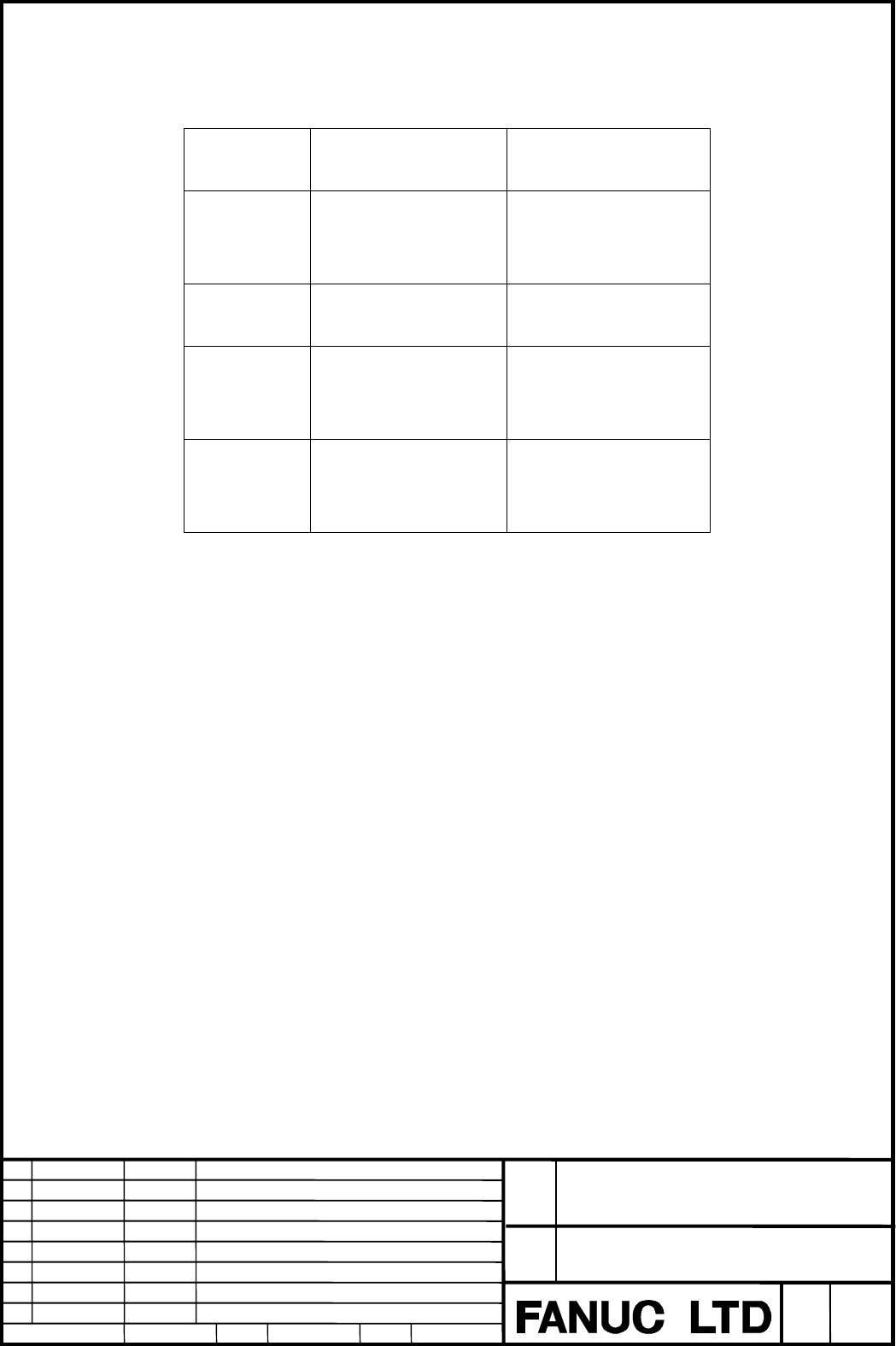
1.1. Operation mode
Operation modeOperation mode
Operation mode
Both grinding heads have cylindrical and non-cylindrical grinding function, so as the
operation following 4 mode is available.
Operation
mode
Head-1 Head-2
Mode-1
Non-cylindrical
grinding
㧔
Binary operation
㧕
Non-cylindrical
grinding
㧔
Binary operation
㧕
Mode-2
Cylindrical grinding
㧔
ISO operation
㧕
Cylindrical grinding
㧔
ISO operation
㧕
Mode-3
Non-cylindrical
grinding
㧔
Binary operation
㧕
Cylindrical grinding
㧔
ISO operation
㧕
Mode-4
Cylindrical grinding
㧔
ISO operation
㧕
Non-cylindrical
grinding
㧔
Binary operation
㧕
These modes are controlled by two path control function, grinding head 1 is controlled
corresponding to path 1 and grinding head 2 is controlled corresponding to path 2.
1.2.
1.2.1.2.
1.2. Rotation control of workpiece
Rotation control of workpieceRotation control of workpiece
Rotation control of workpiece
In this system the rotation of workpiece is controlled by C,A axes only in path 1.
The motion of head 1 and head 2 must be synchronized with C,A axis by binary
programming while non-cylindrical griding is executed
Mode-1:
C,A axes is driven by the binary command in path 1, however the same binary data
commanded in path 1 must
be commanded to C,A axis as dummy in path 2.
Both heads can be synchronized with the motion of C,A axes.
Mode-2:
C,A axes must be commanded by ISO program in path 1, however they need not be
commanded by ISO program in path 2.
Each head moves individually, and head 2 can not be synchronized with the motion of
C,A axes.
Contents Summary of FANUC Series 160i-TA, Binary code controlled axes combined with re-composition control on 2 CPU 2Paths control Additional Manual
- Page 1FANUC Series 160i-TA 160 -TA Binary code controlled axes combined with re-composition control on 2 CPU 2 Paths control Description FANUC Series 160i-TA Title Binary code controlled axes combined with re-composition control on 2 CPU 2 Paths control Draw No. A-76428 Edit Date Design Description Sheet
- Page 21. Outline This function realizes various grinding, such as cylindrical grinding or non-cylindrical grinding with dual grinding heads simultaneously. The cylindrical grinding is commanded by ISO program because of it’s simple command, and non-cylindrical grinding is commanded by binary program becau
- Page 31.1. Operation mode Both grinding heads have cylindrical and non-cylindrical grinding function, so as the operation following 4 mode is available. Operation Head-1 Head-2 mode Non-cylindrical Non-cylindrical Mode-1 grinding grinding 㧔Binary operation㧕 㧔Binary operation㧕 Cylindrical grinding Cylindri
- Page 4Mode-3: C,A axes must be commanded by binary program in path 1, however they need not be commanded by ISO program in path 2. Start timing of head 2 can be adjusted by the standard waiting function by M code. Mode-4: C,A axes must be commanded by binary program in path 2, however they need not be com
- Page 52.1. 2 Paths Binary operation On the FANUC series 16i-TA 2 paths system, binary programming operation with the data which is called out from DATA Server by M198 is possible in path 1 or path 2 or both paths. 㧔Path 1㧕 㧔Path 2㧕 O0001; O0002; G28 U0.0 Z0.0; G28 U0.0 Z0.0; : : M198 P1000; M198 P2000; :
- Page 62.2. Waiting function between 2 paths In mode-1, non-cylindrical grinding are executed by both grinding heads. The rotary axes for workpiece, C,A axes, exist in path 1, so binary data for path 1 must be programmed. Further more, workpice must be rotated synchronous with the binary programming for pa
- Page 72.3. Binary synchronous operation In mode-4, non-cylindrical grinding is executed in path 2. So binary data include C,A axes command must be programmed in path 2. When C,A data is commanded in path 2, actual rotary axis for worpiece, C,A axes, in path 1 are driven by this “Binary synchronous operati
- Page 83. Grinding Mode 3.1 Mode-1: Non cylindrical(path 1) - Non cylindrical(path 2) Non cylindrical grinding by binary command is executed with both grinding heads. The motion of rotary axis for workpiece is commanded with the binary data in path 1. In path 2, the same binary data of C,A axes that is com
- Page 93.2. Mode-2 : Cylindrical(path Cylindrical(path 1) – Cylindrical(path 2) Both heads executes Cylindrical grinding with ISO programming. The rotary axis (C,A axes) for workpiece must be programmed only in path 1. Concerning waiting function and interrupting function, those of standard 2 path control
- Page 103.4. Mode-4 : Cylindrical(path 1)㧙 1)㧙Non cylindrical(path 2) ISO programming operation in path 1, and binary programming operation in path 2 are executed. The rotary axis (C,A axes) for workpiece must be programmed by binary in path 2. Real rotary axis for workpiece, exist in path 1, is driven by b