FANUC Series 30i/31i/32i-MODEL A, Guidance Screen for Tilted Working Plane Command, Specifications Additional Manual Page 20
Additional Manual
type) / present feature coordinate system (in case of the incremental type).
Among the directions normal to the X-axis, a direction with a smaller
angle relative to the P1 → P3 vector is the Y-axis of the feature coordinate
system.
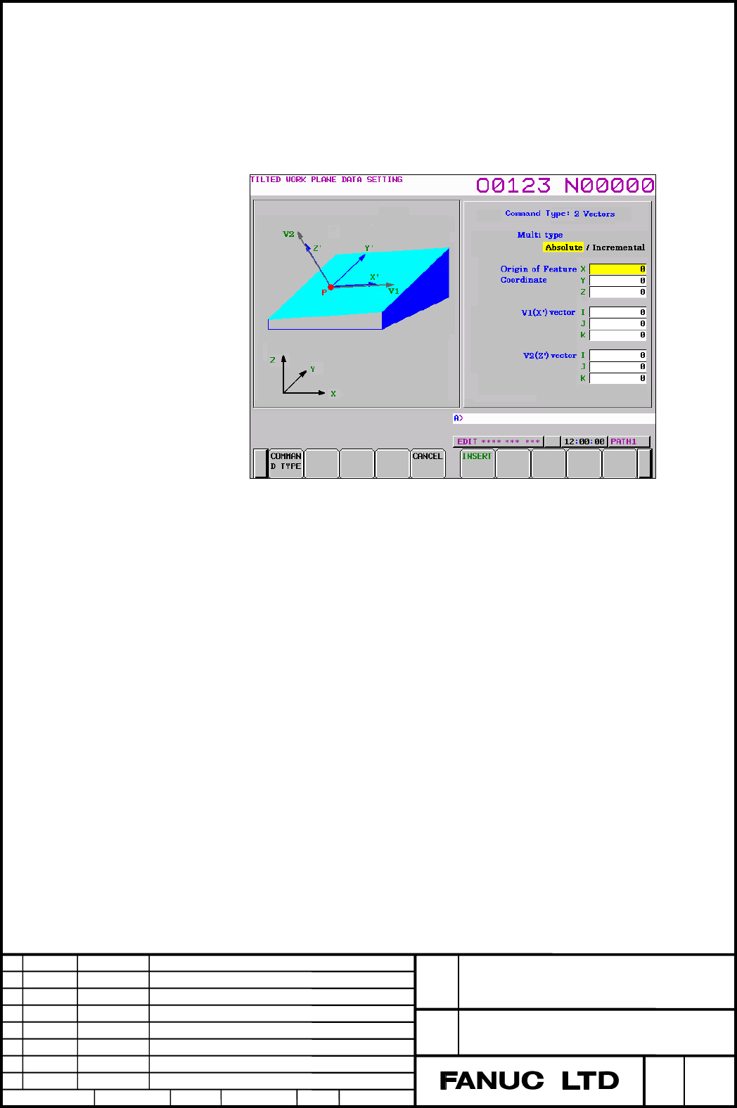
G68.2(2vectors)
Fig. 1.2 (h) Data setting screen - 2 vectors
・Multi type
Absolute: Feature coordinate system is transformed from workpiece
coordinate system.
Incremental: Feature coordinate system is additionally transformed
from present feature coordinate system.
・Origin of Feature Coordinate
Specify the origin (X, Y, and Z of point P) of the feature coordinate
system as coordinates in the workpiece coordinate system (in case of the
absolute type) / present feature coordinate system (in case of the
incremental type).
・V1(X’) vector
Specify the direction of X axis vector of feature coordinate system in the
workpiece coordinate system (in case of the absolute type) / present
feature coordinate system (in case of the incremental type).
・V2(Z’) vector
Specify the direction of Z axis vector of feature coordinate system in the
workpiece coordinate system (in case of the absolute type) / present
feature coordinate system (in case of the incremental type).
A-90404 E
Title
Draw
No.
20/24
Sheet
FANUC Series 30
i
/ 31
i
/ 32
i
Guidance screen for
Tilted Woking Plane command
Edit
Apprv.
Desig.
Date
Design
Descri
p
tion
Date
Feb.02.2006
Contents Summary of FANUC Series 30i/31i/32i-MODEL A, Guidance Screen for Tilted Working Plane Command, Specifications Additional Manual
- Page 1FANUC Series 30i /31i /32i -MODEL A Guidance screen for Tilted Working plane command. Specifications FANUC Series 30i/ 31i/ 32i Title Guidance screen for Tilted Woking Plane command Draw A-90404 E No. Edit Date Design Description Sheet 1/24 Date Feb.02.2006 Desig. Apprv.�
- Page 2Contents 1.1 OVERVIEW ·········································································· 3 1.2 GUIDANCE SCREEN FOR TILTED WORKING PLANE COMMAND 4 1.2.1 COMMAND TYPE SELECTION SCREEN ··················································· 11 1.2.2 DATA SETTING SCREEN ·····························
- Page 31.1 OVERVIEW The guidance screen for tilted working plane command is a function for creating a tilted working plane command block by entering tilted working plane data on the screen. With this function, a complicated tilted working plane command block can be created easily. This function is availabl
- Page 41.2 GUIDANCE SCREEN FOR TILTED WORKING PLANE COMMAND The guidance screen for tilted working plane commands (hereinafter referred to as the guidance screen) consists of a command type selection screen and a data setting screen. The command type selection screen is for selection of a tilted working pl
- Page 5The program editing screen is displayed. 2. With the cursor keys, move the cursor to a position where you want to insert a block. Please note that a block created on the guidance screen is inserted after the block where the cursor is placed. (If the block where the cursor is placed includes a tilted
- Page 65. Select a command type with the cursor keys then press the soft key [SELECT]. The data setting screen is displayed. 6. Enter parameters in the setting items. 7. Press the soft key [INSERT]. 8. Press the soft key [YES]. The screen display returns to the program editing screen then the new block is
- Page 7Modification to an existing block The following shows the procedures to modify and replace the block of tilted working plane command that is already exist in program being edited. 1. On a program editing screen, display the program to be edited. (For the procedure for displaying a program editing sc
- Page 8The data setting screen is displayed. 5. Modify the setting items. 6. Press the soft key [REPLACE]. 7. Press the soft key [YES]. The screen display returns to the program editing screen then the block of the cursor position is replaced to the block created according to the modified setting. FANUC Se
- Page 9Guidance screen cancellation When the soft key [CANCEL] is pressed on the guidance screen, the screen display returns to the program editing screen. At this time, data set on the guidance screen is discarded. NOTE 1. In addition to the above mentioned, the following operations also interrupt the gui
- Page 10Notes ・Condition that the soft key [GUIDANCE] is display The condition for displaying the soft key [GUIDANCE] on a program editing screen is as follows: 1. Foreground editing screen ・The CNC mode is EDIT, TJOG, or THND. ・Editing and display operations are not prohibited on the editing target program
- Page 111.2.1 COMMAND TYPE SELECTION SCREEN The command type selection screen is used to select a type of tilted working plane command to be inserted into an editing target program. One of the following command types can be selected: -G68.2/G68.4 Euler’s angle. -G68.2/G68.4P1 Roll-Pitch-Yaw angle. -G68.2/G6
- Page 121.2.2 DATA SETTING SCREEN The data setting screen is used to set tilted working plane specification data necessary for a selected command type, which is selected on the command type selection screen, or selected by pressing the soft key [GUIDANCE] on program editing screen. The data setting screen v
- Page 13Parameter input ・Items where a value is input 1. With the cursor keys <↑> and <↓>, move the cursor to an item to be set. 2. Key in a desired value then press the key. Example) When the origin of a feature coordinate system is set as shown above, addresses X, Y, and Z are as follows: G68.2 X0
- Page 14Example) G00 X0.; When the guidance screen is displayed and the ↓ 3 points method is selected as the command type here for block insertion, a created block is inserted after the block of cursor position. G00 X0.; G68.2 P2 Q0... G68.2 P2 Q1... G68.2 P2 Q2... G68.2 P2 Q3... Replacement of a block If t
- Page 15Restrictions Following table shows the warnings that may be output at the time of insertion/replacement of block. If a warning is displayed, return to the program editing screen with the soft key [CANCEL] then press the soft key [GUIDANCE] again or correct the cause of the warning then retry. Warnin
- Page 161.2.3 DETAILS OF DATA SETTING SCREEN Following six tilted working plane commands are supported. For details of each command, refer to Section 21.2, "TILTED WORKING PLANE COMMANDS", in Part II of "User's Manual" (B-63944E). -G68.2/G68.4 Euler’s angle. -G68.2/G68.4P1 Roll-Pitch-Yaw angle. -G68.2/G68.4
- Page 17J: Specify rotation angle around the X-axis of coordinate system 1. This rotation determines coordinate system 2 (X2-Y2-Z2) from coordinate system 1 (X1-Y1-Z1). K: Specify rotation angle around the Z-axis of coordinate system 2. A workpiece coordinate system whose origin is shifted by the coordinate
- Page 18・Origin of Feature Coordinate Specify the origin (X, Y, and Z of point P) of the feature coordinate system as coordinates in the workpiece coordinate system (in case of the absolute type) / present feature coordinate system (in case of the incremental type). ・Rotation Angle around X-axis Specify rot
- Page 19Fig. 1.2 (e) Data setting screen - 3 points specification ・Multi type Absolute: Feature coordinate system is transformed from workpiece coordinate system. Incremental: Feature coordinate system is additionally transformed from present feature coordinate system. ・Shift of the Origin Specify a shift a
- Page 20type) / present feature coordinate system (in case of the incremental type). Among the directions normal to the X-axis, a direction with a smaller angle relative to the P1 → P3 vector is the Y-axis of the feature coordinate system. G68.2(2vectors) Fig. 1.2 (h) Data setting screen - 2 vectors ・Multi
- Page 21G68.2(Projection angle) Fig. 1.2 (i) Data setting screen - projection angle ・Multi type Absolute: Feature coordinate system is transformed from workpiece coordinate system. Incremental: Feature coordinate system is additionally transformed from present feature coordinate system. ・Origin of Feature C
- Page 22G68.3 (Tool Axis Direction) Fig. 1.2 (f) Data setting screen - Tool Axis Direction (In the case of Feature Coordinate ‘No’) Fig. 1.2 (g) Data setting screen - Tool Axis Direction (In the case of Feature Coordinate ‘Yes’) ・Origin command of Feature Coordinate Select whether to specify a feature coord
- Page 23・Origin of Feature Coordinate Specify the origin (X, Y, and Z of point P) of the feature coordinate system as coordinates in the workpiece coordinate system. This setting cannot be made if "No" is selected in Origin command of Feature Coordinate. ・Rotation Angle around the Z-axis in F-Coordinate Spe
- Page 241.3 PARAMETER #7 #6 #5 #4 #3 #2 #1 #0 11304 GGD [Input type] Parameter input [Data type] Bit NOTE When this parameter is set, the power must be turned off before operation is continued. #1 GGD The G-code Guidance Screen is 0: Not displayed. 1: Displayed. FANUC Series 30i/ 31i/ 32i Title Guidance scr